Just go to http://soldersmoke.com. On that archive page, just click on the blue hyperlinks and your audio player should play that episode.
http://soldersmoke.com
In this video, Nick M0NTV takes on a hot topic in ham radio homebrewing: The matching of diodes in diode ring mixers. How should the matching be done and -- more controversially -- is this matching necessary?
I won't spoil it for you by giving the answer. Watch Nick's video to find out if it matters. (But a hint appears below.)
I think it is great that Nick has taken the trouble to look carefully at this issue, and has found info that will be of great use to homebrewers. And I really liked Nick's response to the fellow who suggested just going out and buying a commercial diode ring: Nick replied that he homebrews because he likes to, and because he wants to know how these circuits work. FB Nick.
I was also pleased that Nick gave some much warranted recognition to Pete Juliano for his idea regarding the placement of a trim pot on a diode ring. This idea made it into the Experimental Methods in RF Design book (under Pete's old call: W6JFR). Page 6.56.
Phase noise is an undesired variation in the phase of the signal. In this case, an oscilloscope shows that the time between zero crossings of the signal varies over time when compared to the zero crossings of an ideal sine wave. An exaggerated example of phase noise is shown above.
Phase noise on an oscillator signal has exactly the same effect as frequency modulating the oscillator with noise.
Whenever a carrier is passed through a mixer, the phase noise of the oscillator driving that mixer is added to the carrier.
Phase noise on a transmitted signal causes effects identical to phase noise generated in a receiver.
Any signal that reaches a mixer in the receiver is modulated by the phase noise in the local oscillator driving that mixer. As such, the signal appears to have at least as much phase noise as the local oscillator. Thus, sufficiently strong signals off the receiving frequency can degrade receiver sensitivity by raising the noise floor at the receiving frequency. Receiver dynamic range is reduced as the noise floor rises.
With a frequency-shift-keyed or- a phase-shift-keyed signal, the close-in phase noise limits the maximum bit error rate that the system can achieve. Both of these effects can be quantified once the communications system is defined. With an SSB voice signal, the effects are much harder to predict, but excessive phase noise does degrade SSB signal intelligibility to some extent.
--------------------------------
Receiver guru Rob Sherwood provides some very useful historical background on his web site:
Phase Noise: Old radios (Collins, Drake, Hammarlund, National) used a VFO or PTO and crystal oscillators to tune the bands. Any noise in the local oscillator (LO) chain was minimal. When synthesized radios came along in the 70s, the LO had noise on it. It is caused by phase jitter in the circuit, and puts significant noise sidebands on the LO. This can mix with a strong signal outside the passband of the radio and put noise on top of the weak signal you are trying to copy. This is a significant problem in some cases: You have a neighboring ham close by, during Field Day when there are multiple transmitters at the same site, and certainly in a multi-multi contest station. You would like the number to be better that 130 dBc / Hz at 10 kHz. A non-synthesized radio, such as a Drake or Collins, has so little local oscillator noise the measurements were made closer-in between 2 and 5 kHz.
-------------------------------------
Experimental Methods in RF Design (EMRFD) has this to say about phase noise:
"The local oscillator is a critical part of any communications system. Modern transceiver performance is often compromised by LO systems that suffer from excess phase noise, effectively limiting the receiver dynamic range. While quiet oscillators, those with low phase noise, can be built using traditional methods, these circuits often lack the thermal stability of a synthesizer.... Frequency synthesis is not, however, the answer to all the LO problems presented to the experimenter. Some PLL synthesizers are burdened by excessive phase noise. Those using DDS, while quieter, emit spurious outputs, often in profusion. Both use an excess of digital circuitry that can often corrupt a receiver environment." page 4.1
"At first glance, phase noise sounds like an esoteric detail that probably has little impact on practical communications. This is generally true." page 4.12
--------------------------------------
Hans Summers G0UPL analyzed and measured the phase noise of the Si5351a chip:
Lee KD4RE of the Vienna Wireless Society has been talking about the Franklin oscillator. He has been telling us that it is very stable, and capable of stable operation up through the ten meter band. Lee wants to build an direct conversion receiver for all of the HF bands with one of these circuits.
I was skeptical. First, I'd never heard of this circuit. I'd grown up in ham radio on a steady diet of Hartley and Colpitts and Pierce. Vackar or Clapp were about as exotic as I got. And second, I'd come to accept that it is just not possible to build a good, stable, simple, analog VFO for frequencies above around 10 MHz. For example, in his Design Notebook, Doug DeMaw wrote, "VFOs that operate on fundamental frequencies above, say, 10 MHz are generally impractical for use in communications circuits that have receivers with narrow filters." DeMaw was known for resorting to variable crystal oscillators.
But then this month Mike Murphy WU2D put out two videos about his use of the Franklin oscillator circuit in a direct conversion receiver at 21 MHz. The VFO was shockingly stable. I began to believe Lee. I fired up my soldering iron and built one.
WU2D's Franklin Oscillator
Lee was right, it is in fact remarkably stable, even at higher frequencies. My build (see picture above) was a bit slap-dash and could be improved a bit, but even in these circumstances here is what I got. This was with a stable 6 Volt Supply and with only a cardboard box covering the circuit:
Local time Frequency
0543 19.1114 MHz (cold start)
0636 19.1116
0804 19.1117
1034 19.1118
1144 19.1117
I started digging around for references to the Franklin. There was nothing about it in Solid State Design for the Radio Amateur, nor in Experimental Methods of RF Design. Pat Hawker G3VA (SK) did discuss it in his Technical Topics column in RADCOM, February 1990. Pat gave a great bio on Charles S. Franklin (born in 1879 and a colleague of Guillermo Marconi). But tellingly, Pat writes that, "Despite its many advantages, the Franklin oscillator remains virtually unknown to the bulk of American amateurs."
QST "How's DX" August 1947
It wasn't always unknown. In the 1940s, we see articles about the Franklin oscillator circuit. There is a good one in the January 1940 issue of "Radio." The authorW6CEM notes that the circuit "is probably familiar to only a few amateurs." It shows up in the "How's DX" column (above). And the 1958/1959 issue of Don Stoner's New Sideband Handbook we see a lengthy description of the Franklin oscillator. Stoner wrote: "The author's favorite oscillator is the 'old time' Franklin, and it is believed to be the most stable of them all! This rock-solid device can put a quartz crystal to shame! Because it represents the ultimate in stability, it is the ideal VFO for sideband applications." And we see a PTO-tuned Franklin oscillator in the July 1964 QST. And it is in the fifth edition of the RSGB Handbook (1976).
Here is the January 1940 "Radio" with the Franklin oscillator article on page 41 by W6CEM:
Look, there may be reasons why the Franklin oscillator has been ignored. But the circuit sure seems to present a lot of advantages. Stable operation beyond the 10 MHz barrier is the big one. Simplicity is another. If there are problems and shortcomings, let's hear about them. But it seems as if the Franklin oscillator may provide the opportunity for us to build stable VFOs beyond 10 MHz without resort to complicated PLL stabilization techniques, and without opting to go with an Si5351 or other complex digital devices.
So let me ask: Why hasn't the Franklin oscillator been given more attention, and why haven't we seen more use of this circuit by hams or even by manufacturers?
But until now, I never built one. Recently, Dean KK4DAS and the Vienna Wireless Makers group have been building a Direct Conversion receiver. Their receiver uses an Si5351 as the VFO, but of course Dean and I have decided to try to do things the hard way by building non-digital VFOs. At first we just came to the conclusion that my earlier Ceramic Resonator VFO wasn't much good (it drifted too much). This led us into standard Colpitts and Armstrong VFOs, and the fascinating world of temperature compensation. Then I remembered the Polyakov circuit -- this would allow us to use a 3.5 MHz VFO on the 7 MHz band. Lower frequency VFOs are easier to stabilize, so I started building my first Polyakov receiver. You can see the results (on 40 meters) in the video above.
I started working with a circuit from SPRAT 110 (Spring 2002). Rudi Burse DK2RS built a Polyakov receiver for 80 and 40 that he called the Lauser Plus. (Lauser means "young rascal" or "imp" in German.) For the AF amplifier, I just attached one of those cheap LM386 boards that you can get on the internet. With it, I sometimes use some old Iphone headphones, or an amplified computer speaker.
The Polyakov mixer is a "switching mixer." The book excerpt below shows how I understand these circuits. The enlightenment came from the Summer 1999 issue of SPRAT (click on the excerpt for an easier read):
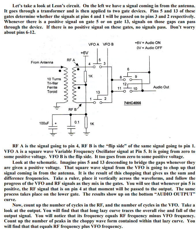
Leon's circuit shows us how a simple switching circuit in which the switches are controlled by the VFO can result in an output that has the sum and difference components. That is the hallmark (and most useful part) of real mixing. Remember -- we say that mixing happens in non-linear circuits when the passage of one signal depends on what is happening with the other signal. A switch is as non-linear as you can get! And that switch is being controlled by the VFO.
In a Direct Conversion receiver we usually run the VFO at the operating frequency. This results in audio just above and just below the operating frequency.
The Polyakov Direct Conversion circuit is a bit different. It has the switches (the diodes) turned on twice each cycle: When the VFO voltage goes to a positive peak, this turns on one of the diodes. When the VFO goes to a negative peak, this turns on the other diode. So in effect the switch is being turned on TWICE each cycle. So with the Polyakov you run the VFO at HALF the operating frequency. For a DC receiver designed to run around 7.060 MHz, you build a VFO at around 3.53 MHz. This has some immediate advantages. My favorite is that it is easier to get a VFO stable at a lower frequency. It is easier to stabilize a VFO at 3.53 MHz than it is at 7.060 MHz.
When you open that SW 1 switch in the Lauser Plus, you no longer have a Polyakov mixer. Now you just have a diode mixer. It will be opening and closing once each cycle at the VFO frequency. DK2RS used this to cover not only the 40 meter band (in Polyakov mode) but also the 80 meter band (in single diode detector mode). That is why DK2RS has that big variable capacitor in the input circuit -- that LC circuit needs to tune all the way down to 3.5 MHz and all the way up to around 7.3 MHz. (I used a coil of about 6.5 uH to do this.)
With just one diode and operating at 80 meters, it works, but not as well as it does in the Polyakov mode on 40. I can pick up 80 meter signals, but in this mode there seems to be more of an "AM breakthrough" problem. "Experimental Methods in RF Design" on page 8.11 describes what is going on (the last sentence is most relevant here):
Here are some very good links with information on the Polyakov receiver:
LA8AK SK: http://www.agder.net/la8ak/ Almost seventeen years after his death he continues to help his fellow radio amateurs through his web sites. TNX OM! FB!
We've frequently said that is pays to check the W7ZOI web site. Tony G4WIF did just that and pointed us in that direction, noting that the LADPAC "Ladder Package" software is now available for download from that site.
Homebrewers will really want to have that package on their computers. There are all kinds of useful programs in that package: software for designing crystal filters and feedback amplifiers, a program that allows you to think systematically about receiver gain distribution and dynamic range, and many other useful things.
I built the transmitter almost 20 years ago. It is in the larger box, which originally housed a Heathkit DX-40. There is a lot of soul in that old machine. Details on this construction project are here: https://soldersmoke.blogspot.com/2021/12/junk-box-sideband-from-azores-2004-qst.html(The smaller box is a Barebones Superhet receiver set up for 17 meters.)
In the 2004 QST article I discuss a problem I had with "spotting" or "netting." This is something of a lost art, something that you had to do back in the pre-transceiver days, when running a separate transmitter and receiver. This was how you got the transmitter on the receiver's frequency. Essentially you would turn on the carrier oscillator and the VFO and let a little signal get out, enough to allow you to tune the VFO until you heard zero beat on the receiver. My problem was that around one particular frequency, I would hear several zero-beats. This made netting the receiver and the transmitter hard to do.
Important note: This is really just a problem with the "netting" or "spotting" procedure -- the problematic spur does not show up in any significant way in the output of the transmitter. I can't see it on my TinySA. But it is strong enough to be heard in the unmuted receiver sitting right next to the transmitter. And that creates the netting problem.
In the QST article, I said that I noticed that the problem seemed to be centered around 18.116 MHz. As I approached this frequency, the tones -- desired and unwanted -- seemed to converge. That was an important clue. In the article I said I thought that I could eliminate the problem with just one trimmer cap to ground in the carrier oscillator, but looking back I don't think that this really fixed the problem.
I recently took a fresh look at it. Exactly which frequencies were causing the unwanted signals that appeared in my receiver?
I used an Excel Spread sheet to find the culprits.
The first column shows the carrier oscillator and its harmonics. The second column shows the VFO when tuned for a signal at 18.11668 MHz (23.2927-5.17602), along with its harmonics. Check out the 10th harmonic of the carrier oscillator and the third harmonic of the VFO: 69.8781-51.7602 = 18.1179. Those two harmonics would produce the problem I had been experiencing.
I turned to one of Wes Hayward's programs for confirmation. Spurtune08 came in the EMRFD software package. Here is what I saw when I plugged in the above frequencies:
You can see the little spur off to the left of the main signal. In the program, as I tune the 23 MHz VFO frequency, the spur moves closer to the main frequency as I approach 18.116 MHz, just as it does in the real rig. Note that I have only turned on the 10th harmonic of the carrier oscillator and the 3rd harmonic of the VFO. Spurtune08 is very useful. Thanks Wes!
So, what is to be done? For now, I am just restricting my operations on 17 meters to above 18.120 MHz. (I worked several DX stations with it on December 27.) But obviously I need to fix this. This rig needs an exorcism. I think I only need to get rid of one of the harmonics, and the 10th harmonic of the carrier oscillator seems easier to kill. I'm thinking of putting the carrier oscillator in an Altoids box, and then adding some filters to knock down the 10th harmonic.
Here is the G3YCC schematic that inspired this rig. I used G3YCC's carrier oscillator and balanced modulator circuits, just using a 5.176 MHz crystal and changing the tank circuit in the collector:
How would you folks knock down that 10th harmonic?
The presentation starts at about the 4 minute point.
I think if I were only allowed to watch one YouTube video in the next year, I'd make it this one.
In this amazing RSGB video, Ashhar Farhan VU2ESE takes us back to his earliest days as a radio amateur. He tells us about his very early desire to build radios, his early projects, and his personal evolution as a designer and builder, from a simple DC receiver, to the BITX, the Minima, the uBITX and now the hybrid HDR/SDR sBITX.
There is a lot of homebrew wisdom and tribal knowledge in this video. And we learn so many hitherto unknown details about the rigs that have become so important to us:
-- Farhan had the EMRFD book with him on the famous flight from Sweden to India during which the BITX was designed.
-- We learn about the origins of the BITX oscillator circuits, and that the VFO and BFO are essentially the same.
-- I was really pleased that Farhan included a picture of my HB BITX17 rig in his presentation.
-- Farhan discusses the difficulties he faced in obtaining needed parts in India.
-- We actually see the nylon washers that Farhan used in the original BITX.
-- Farhan discusses his early system for measuring coil inductance.
-- In addition the huge contribution of EMRFD, Farhan talks about how he was helped by Pat Hawker G3VA's writing, and the ARRL's SSB Handbook.
-- Farhkan talks about his Tex 465 'scope and his building of a Spectrum Analyzer.
-- We see his evolution to dual conversion. We see the conceptual birth of the Minima and the birth (thanks Wes!) of the TIA amps. I didn't know about the HF-1. Then Farhan designed the uBITX and now the sBITX.
-- Farhan talks about his practice of taking the pictures of new rigs with the new rig sitting atop the book that was most important in its design and construction. FB.
-- I was really blown away by Farhan's presentation of how the uBITX advertisement was inspired by and in many ways based on the Heathkit ad for an HW-101. Amazing.
-- I learned a lot from Farhan's discussion of SDR theory. I pledge to spend more time with this. I really like Farhan's hybrid HDR/SDR approach.
-- But I have a question: Farhan seems to say that we'd need a big expensive GOOGL computer to do the direct sampling HF SDR. But doesn't the little RTL-SDR do just that? Without a GOOGL?
-- Great to see Wes's AFTIA being used in the sBITX.
-- Really cool that Farhan has his mind on VHF transverters when designing the sBITX. I liked use of the TCXO module to free up one of the Si5351 clock outputs. FB. And great to include an idea from Hans in this rig.
Thanks very much to Farhan (who stayed up until 3 am to do this!) and to the RSGB for hosting.
Here is Farhan's amazing presentation to the virtual 2021 FDIM event. There is a lot of tribal knowledge in this video. Lots of old and new technology. I was especially intrigued by Chris Trask's Kiss mixer. Farhan's discussion of simple Arduino-based speech equalization and compression made me think that I have work to do in this area. And of course, Farhan's whole discussion of how to bring SDR into -- literally into -- the circuitry of a uBITX is really cool and very educational.
This is obviously very cool, but looking ahead I think Adam should think about adding one more mixer, changing the bias on the TX amps, and adding a mic amp. Boom: A Double Sideband Transceiver.
Pete wrote: When I was in the US Navy and a particular unit did something outstanding – the Command ship would raise the Bravo Zulu Flag for a job well. Don’t know if you can see it there in MO but I have raised the BZ flag to you. Outstanding and congratulations.
Bill and Pete:
Just finished a DC transceiver using Arduino nano, SI5351 (my sincerest apologies, Bill), diode ring mixer and lm386 audio amp. The transmit portion is a two-stage class AB pre-amp (from EMRFD page 2.32), which is driving an IRF510 final (biased at 2.08 volts) from Pete’s design. Output is about 5watts into a CWAZ low pass filter, based on the design from here: https://www.arrl.org/files/file/Technology/tis/info/pdf/9902044.pdf
I’m using a manual TX/RX switch which is doing multiple things. It brings the Nano A1 LOW, offsetting the transmit frequency 600 Hz for CW, grounds the audio input to prevent deafness (learned that one the hard way), and it engages a relay that switches the antenna from the receiver to the transmit, and also turns on the transmitter stages. Keying is through the first stage of the pre-amp. I still have some tidying up to do, and I’m not sure the LPF works so well using two component inductors instead of all toroids, but I finished it today and made my first QSO into Ontario almost 1000 miles away. It’s been great fun! 73, Adam N0ZIB Missouri
I've been having a lot of fun with the Lafayette HA-600A receiver that I picked up earlier this month. Adding to the mirth, I noticed that on SSB, the signals sound a bit scratchy, a bit distorted, not-quite-right. (I'm not being facetious; this is an interesting problem and it might give me a chance to actually improve a piece of gear that I -- as a teenager -- had been afraid to work on.)
Before digging into the circuitry, I engaged in some front panel troubleshooting: I switched to AM and tuned in a strong local AM broadcast signal. It sounded great -- it had no sign of the distortion I was hearing on SSB. This was an important hint -- the only difference between the circuitry used on AM and the circuitry used on SSB is the detector and the BFO. In the AM mode a simple diode detector is used. In SSB a product detector and BFO is used. The BFO sounded fine and looked good on the scope. This caused me to focus on the product detector as the culprit.
Check out the schematic above. Tr-5 is the product detector. It is really, really simple. (See Einstein quote below.) It is a single-transistor mixer with BFO energy going into the base and IF energy going into the emitter. Output is taken from the collector and sent to the audio amplifiers. (A complete schematic for the receiver can be seen here: https://nvhrbiblio.nl/schema/Lafayette_HA600A.pdf )
I had never before seen a product detector like this. One such detector is described in Experimental Methods for RF Design (page 5.3) but the authors devoted just one paragraph to the circuity, noting that, "We have not performed careful measurement on this mixer." The lack of enthusiasm is palpable, and probably justified.
To test my suspicion that the product detector is the problem, I set up a little experiment. I loosely coupled the output of a signal generator to the IF circuitry of the HA-600A. I put the sign gen exactly on the frequency of the BFO. Then, I switched the receiver to AM, turning off the BFO and putting the AM diode detector to work. I was able to tune in the SSB signals without the kind of distortion I had heard when using the product detector.
So what do you folks think? Is the product detector the culprit? Or could the problem be in the AGC? Should I start plotting a change in the detector circuitry? Might a diode ring work better?
"SolderSmoke -- Global Adventures in Wireless Electronics" is now available as an e-book for Amazon's Kindle.
Here's the site:
http://www.amazon.com/dp/B004V9FIVW
Re: 15-meter POTA SSB population
-
You said: *"Funny .. even the ARRL has removed the de facto 21.430 MHz AM
Calling frequency"*
I don't remember the ARRL ever Id'ing an AM "Calling Frequenc...
April 22, 2024. Did you miss this Subtlety?
-
*Our 12MHz IF Amp plot out to 100MHz *
In yesterday's posting I shared a 9MHz IF Amp using the J310's configured
as a Dual Gate MOSFET. Soon...
An Inline RF Step Attenuator for QRPp Work
-
I don’t need to explain the attraction of low power operation; if you’re
reading this, the chances are that you are already a convert. I’ve been
operating ...
Using an external clock with the RX-888 (Mk2)
-
*The RX-888 (Mk2) and external clocking*
*Figure 1:*
The RX-888 with external clock input *(right)*
The enable/disable switch is barely
visible behind the...
A 51S-1 Restoration Story
-
I came across my Collins 51S-1 in a big junkyard in Ankara, Turkey around
2012. It was in a pile with a lot of other electronic scrap, probably from
one o...
New QRP Cluster Online From OM0ET and OM6APN
-
By DX EXPLORER
DX EXPLORER
Paul OM0ET and Peter OM6APN recently launched a new cluster dedicated to
QRP operations. Have a look and I hope you will enjoy...
3D Printing The Hadley 114mm Newtonian Telescope
-
Yes, we’re building a 3D Printed Newtonian Telescope called Hadley. It’s
being printed in PETG and in the video below, I give a quick tour. My build
isn’...
3D printed project boxes
-
I have been busy with some other things that have kept me away from
electronics projects for quite a while. Now I can get back to them, but
realize I n...
Daylight Again – An all Analog Radio
-
What’s all this? In 10 seconds, A high performance, 7MHz, 5 watt SSB rig
Draws just 24 mA of current 90 dB dynamic range, 80 dB close-in dynamic
range 3D ...
Adding Enclosure to your sBitx Boards Order
-
The early buyers of the sBitx board set who bought it for $270 USD might
want to also add the enclosure (box) for in the kit. What you will now get
is a f...
Digi-chirp! Digital synthesis of ‘nostalgic’ CW
-
The bottom ends of 80, 40 and 20m are not what they used to be. For
starters, the busiest part is the digital segment where computers talk to
computers – l...
-
A Simple Speech Processor
(For QRP/SSB Homebrew Transceivers )
Over the last few weeks I had been thinking to build a small AF speech
processor to add to...
A New Look for your uBitx!
-
Adding a "Cool Blue" Display to your uBitx!
The standard "green background" with black lettering frequently reminds me
that I suffer from Chronic seasickn...