Podcasting since 2005! Listen to Latest SolderSmoke

Friday, September 9, 2016

Oz JOO : An Australian Mighty Mite with 3D Printing


Hi Bill & Pete,

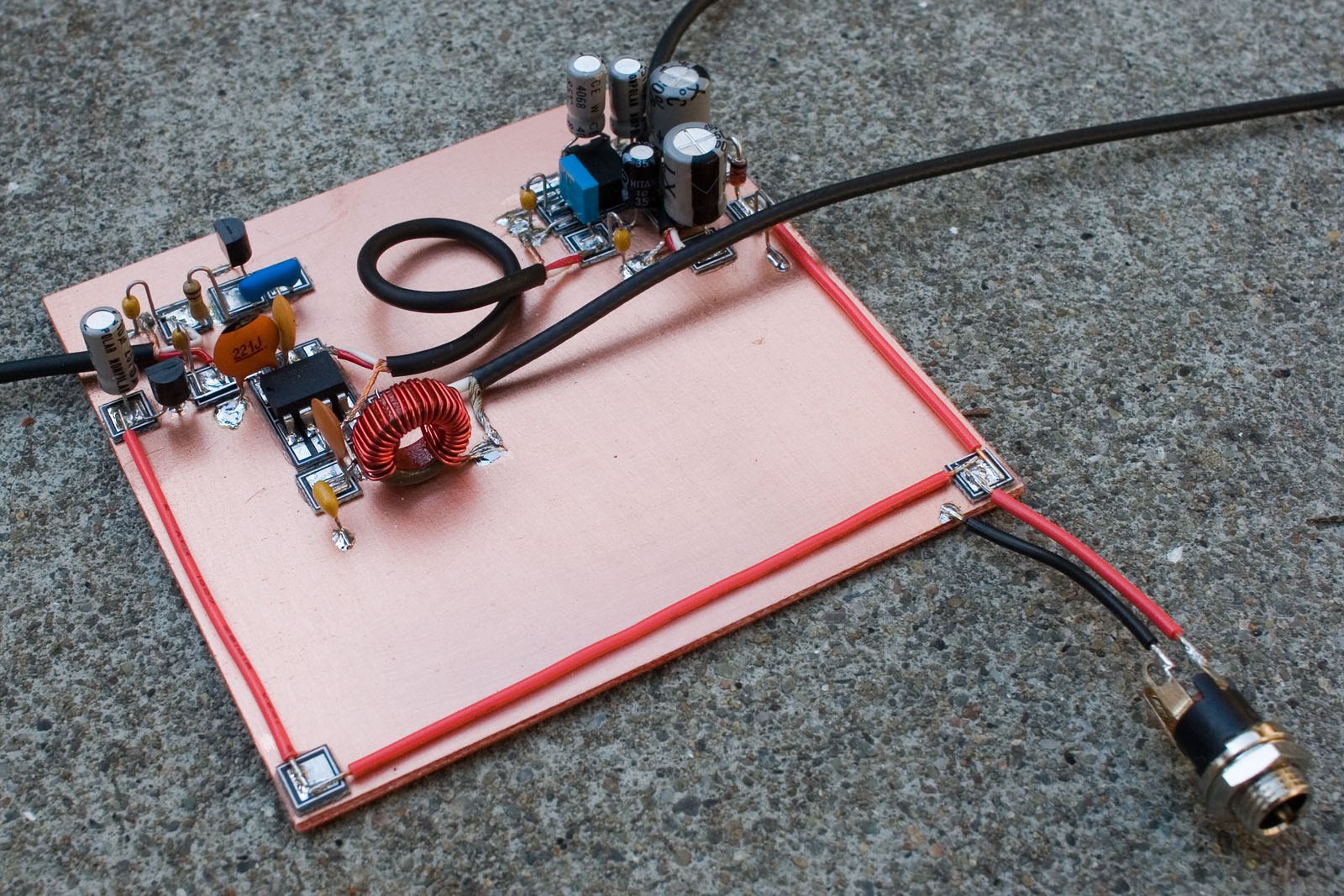
I have the JOO - joy of oscillation! The transistor is a 2N3053 with a clip on heat sink, but I don't think that I really need it. Output power +22dBm or 160mW. When I tested it on a Comms test set  at work, I found that the harmonics were about 12dB to 15dB down and I stopped looking at the 10th harmonic. Not good.

Fitting the 80m low pass filter (salvaged from another project) brought the harmonics more than 50dB down.

The coil former is a 31mm diameter and 3D printed by one of the guys at work. The material is PET - the material they make soft drink bottles from. After we printed it, I put it in a microwave oven with a glass of water. 30 seconds and the water got warm and the coil former stayed cool.

I haven't had a contact yet, but maybe in the next few weeks.

The next project is an 80m CW transmitter based upon the Goodfeller transmitter from QST 1946. It requires a inductor in the pi coupler, 1.5 inch diameter, 32 turns at 20 tip; but where to get one of those these days - wind your own.

I got the guy at work to also 3D print me a coil former with a spiral thread around the outside with a 20tpi pitch for the wire to lay in. Some hot glue and the coil is ready.

Now that I have finished all 189 episodes and two specials, my days are empty. Please make some more.

73 de Peter VK2EMU


Hi Peter (great name BTW),
 
Congratulations –really liked your build – top drawer! 3D printer access WOW – now if I could only get my 3rd son (Mechanical Engineer) to build me one of those machines.
 
The 3D made coil form is perfect for a VFO and follows the principles set down by Doug DeMaw W1FB (SK) about keeping the coil supported at both ends and away from metal. Bill needs a coil like that to mate with his HRO dial mechanism –and follows something old (dial) something new (coil).
 
73’s
Pete N6QW

Wednesday, September 7, 2016

ZL2BMI @ AA7EE -- Possibly the Most Beautiful DSB Rig Ever Built

Dave AA7EE has a very cool blog post on his version of the famed ZL2BMI DSB transceiver (seen above).  As usual, Dave puts most of us to shame with his excellent non-ugly construction and enviable in-focus macrophotography.

Check it out:
https://aa7ee.wordpress.com/2012/07/29/half-of-the-zl2bmi-dsb-transceiver-a-simple-80m-direct-conversion-receiver/

I especially liked Dave's discussion of how and why .1 uF caps are used in the coupling and bypass network between the two chips.

Of course, the only thing I don't like about this rig is the, well, the chips.  Can we persuade Dave to build the earlier discrete component version of this rig?

Be sure to read the many comments on Dave's post.   Our friend Rogier comments on the beauty of it all.  Edgardo LU1AR (the Argentine wizard with the gyrocopter) chimes in.  And we see  feedback from Eric Sears ZL2BMI himself.  FB. 

VIVA DSB! 


Sunday, September 4, 2016

First Signals from the "Armand HROish" Receiver


I've been kind of busy lately with other things, but I have managed to squeeze in a few minutes most days to work on my latest receiver project.  I call it the Armand HROish receiver.  Armand WA1UQO sent me the big National HRO-style dial and gear box, and he was there at the Manassas hamfest when I bought the dual variable cap that now serves in the front end pre-selector.

I went with a 455 kHz IF.   The idea is to have a receiver that tunes from around 6.5 MHz to around 8 MHz so I can do some shortwave listening AND listen to 40 meters.

So far the filter consists of three IF cans (one small transistor can and two larger tube-type cans).  The small transistor can was given to me by Michael Rainey AA1TJ - thanks Mike. Doug DeMaw suggested this use of IF transformers in his "Design Notebook."

At the front end I have a tunable dual tuned circuit filter followed by a 40673 amp. 

The mixer is an SBL-1.

1st and 2nd IF amps are a 23 db 50 ohm termination insensitive amplifiers.

I have a second SBL-1 that will be the product detector, but I haven't built the BFO yet.  So today I hooked up two 1N34A diodes in voltage double config and -- with a bit of AF amplification, got the receiver inhaling with a diode detector.   I could pick up Radio Canada.  Then I heard SSB sigs on 40.  With no BFO, I decided to put my sig gen on 455 kHz and just wrap the lead around the IF cans.  It worked -- I could listen to SSB and CW sigs.  Very satisfying. 

Still to do:
-- BFO and product detector.
-- Work on AF amp.
-- Get my CM-455 crystal mechanical amp in there with some relays around it so I can switch from narrow to broad via the front panel.

Lots of soul in this receiver:  All parts either 1) came out of the junkbox, 2) were gifts from friends, or 3) were recent hamfest purchases.  The HRO dial from Armand and the IF can from AA1TJ.  The 455 kHz filter idea came from Doug DeMaw, the VFO circuit from SSDRA.  The VFO base is from Whole Foods and the whole thing is built on a kitchen cutting board. It includes a 40673 and germanium diodes. The VFO amps are in Altoid tins.  It will, when finished, go into a big metal box given  to me by Tim KI6BGE and shipped east by Pete Juliano.  And when I was working on the 1st mixer, I accidentally pricked my finger and a drop of N2CQR blood went onto the breadboard.  Of course, I left it there.   SOUL!

The Radio Gods are apparently pleased:  In the first hour or so of listening, I was rewarded for my efforts when I managed to hear Tim WA1HLR on 40 AM describe his troubleshooting of an old piece of gear.  TRGHS.  


Wednesday, August 31, 2016

A Signal for SETI? HD 164595


That's the Russian radio-telescope that picked up what was thought to be a possible signal from an extraterrestrial civilization.   This article from the SETI Institute has some interesting tech info on antennas and power levels.  Definitely not QRP!


Monday, August 29, 2016

Update on the PA3GSV M4MMRX -- And a Mystery


Note the establishment of a new acronym (M4MMRX) for Lew McCoy's Mate for the Mighty Midget receiver.  We  have needed this acronym for a long time, and SolderSmoke HQ is proud to have come up with it.  We do our part my friends.

Jan has made more progress on his amazing Dutch M4MMRX and has produced a short video showing the receiver in action with SSB and CW signals. 

Here is a bit of intriguing homebrew mystery:  Jan has gone to a LOT of trouble to create that semi-circular opening in the center of the front panel.  He even cut a corresponding semi-circular hole in the sewer pipe cap that serves as the large wheel in his amazing homebrew reduction drive.  But he won't tell us what he plans to do with that space.  So I ask you, dear SolderSmoke readers:  What is that space for?  Why the see-through panel and sewer-pipe cap?  What is Jan's plan? 

From Jan:

Hi Bill,
 The rattle is gone, so I made a little video of the MMMRX in ssb and cw mode.

In the text, a ch327 and a ch45 crystal is mentioned, but I can’t get this to work.
The ch45 has a 453.6 kHz fundamental, for ch327 can’t find one.
The ch327 is a FT-243 one, tested several, but no fundamental somewhere around 455 kHz.
For ssb there is a ch45 and a ch46 crystal in, which should provide a bandwidth of about 2kHz.
(Still not totally in the clear how this should work with the very narrow resonance response of the crystals.
One should expect two peaks and nothing in the middle?)
For cw I found two ch45 crystals about 130 Hz difference in frequency, which seems to work well.

Still need to correct the 40m oscillator coil, then move on to finishing the receiver.
This is my first home brew tube superhet.
The project isn’t finished yet, but it sure is fun to build, and learned a lot during the process.

73  Jan
Designer: Douglas Bowman | Dimodifikasi oleh Abdul Munir Original Posting Rounders 3 Column