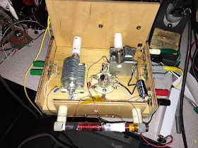
W3JDR's Comment on my post about the DC RX mixer got me thinking. He was right -- my explanation of the mixer action wasn't quite complete, especially as far as switching mixers are concerned. I remembered that I had written about this in the SolderSmoke book. Below you can see the part of the book in which I discuss switching mixers. Realize that the two diodes in F5LVG's mixer play the same role as the two gates in Leon's circuit. It will be worth your while to sit down with Leon's circuit diagram, his frequency chart, and a ruler and really go through this so you can SEE and really understand how the two gates (or switching diodes) generate sum and difference frequencies.
-----------------------
I
guess I still yearned for clarity and intuitive understanding... Time and time again, as I dug into old
textbooks and ARRL Handbooks and
promising web sites served up by Google, I was disappointed.
Then I found it.
It
was in the Summer 1999 issue of SPRAT, the quarterly journal of the G-QRP Club. Leon
Williams, VK2DOB, of Australia
had written an article entitled “CMOS Mixer Experiments.” In it he wrote, “Generally, mixer theory is
explained with the use of complicated maths, but with switching type mixers it
can be very intuitive to study them with simple waveform diagrams.”
Eureka! Finally I had
found someone else who was dissatisfied with trigonometry, someone else who
yearned for the clarity of diagrams.
Leon’s article had waveform diagrams that showed, clearly, BOTH sum and
difference output frequencies.
Switching
mixers apply the same principles used in other kinds of mixers. As the name
implies, they switch the mixing device on and off. This is non-linearity in the extreme.
Not
all mixers operate this way. In
non-switching mixers the device is not switched on and off, instead one of the
signals varies the amount of gain or attenuation that the other signal will
face. And (as we will see) it does this in a non-linear way. But the basic principles are the same in both
switching and non-switching mixers, and as Leon points out, the switching
circuits provide an opportunity for an intuitive understanding of how mixers
work.
Let’s
take a look at Leon’s
circuit. On the left we have a signal
coming in from the antenna. It goes
through a transformer and is then applied to two gate devices. Pins 5 and 13 of these gates determine
whether the signals at pins 4 and 1 will be passed on to pins 3 and 2
respectively. Whenever there is a positive signal on gate 5 or on gate 13,
signals on those gaps can pass through the device. If there is no positive signal on these
gates, no signals pass. Don’t worry
about pins 6-12.
RF A
is the signal going to pin 4, RF B is the “flip side” of the same signal going
to pin 1. VFO A is a square wave
Variable Frequency Oscillator signal at Pin 5. It is going from zero to some
positive voltage. VFO B is the flip
side. It too goes from zero to some
positive voltage.
Look
at the schematic. Imagine pins 5 and 13
descending to bridge the gaps whenever they are given a positive voltage. That square wave signal from the VFO is going
to chop up that signal coming in from the antenna. It is the result of this chopping that gives
us the sum and difference frequencies.
Take a ruler, place it vertically across the waveforms, and follow the
progress of the VFO and RF signals as they mix in the gates. You will see that whenever pin 5 is positive,
the RF signal that is on pin 4 at that moment will be passed to the
output. The same process takes place on
the lower gate. The results show up on
the bottom “AUDIO OUTPUT” curve.
Now,
count up the number of cycles in the RF, and the number of cycles in the
VFO. Take a look at the output. You will
find that that long lazy curve traces the overall rise and fall of the output
signal. You will notice that its
frequency equals RF frequency minus VFO frequency. Count up the number of peaks in the choppy
wave form contained within that lazy curve.
You will find that that equals RF frequency plus VFO frequency.
Thanks Leon!


