Podcasting since 2005! Listen to Latest SolderSmoke

Sunday, January 28, 2018

Building the Ceramic Discrete Direct Conversion Receiver #4 -- The Mixer


I think the most important stage of a direct conversion receiver is the mixer.   This is the stage that takes the RF energy coming in from the antenna and -- in one fell swoop -- turns it into audio.

It is important to understand how this happens.  I go into this in some detail in the SolderSmoke book.  To summarize: 

1) You have two signals going into a non-linear device.  The way in which the smaller signal passes through the device -- how much it is amplified or attenuated -- depends on the instantaneous value of the larger signal.  We are not just adding the two signals together.

2) The waveform that comes out will be a complicated repeating waveform.  We know from Fourier that any complicated repeating waveform can be broken down into sine wave components.

3) When you analyze the complicated repeating waveforms coming out of the mixer, you will find that the sine wave components include a frequency that is the sum of the two inputs and another that is the difference between the two.

So lets suppose we have a non-linear device.  We send in a signal from our oscillator at 7061 kHz. Coming in from the antenna we have a signal at 7060 kHz.   The non-linear device will produce outputs at 14121 kHz (sum)  and at 1 kHz (difference).  We are interested in the difference frequency.  We can HEAR that one.  We feed it into our audio amplifiers and we can copy the Morse Code coming in.  It will sound like a 1 kHz tone going on and off as the operator at the distant station presses his code key.  (We don't really have to worry about the 14121 kHz signal -- it is easily eliminated by filters and would never make it through our audio amplifiers.  And in any case we could not hear it.)

What can we use as a non-linear device?  In this receiver we will use diodes.  Diodes are  extremely non-linear devices. They can be used as on-off switches, with one of the signals determining if they are on (conducting) or off (not conducting).  When used like this they are "switching mixers." In essence, a larger,  controlling signal from the VFO will be turning the diodes on and off. Thus the signal coming in from the antenna will be chopped up by the switching action of the diode being turned on and off.  This is non-linear mixing at its most extreme.  It will definitely produce the sum and difference products we are looking for.

We could build the mixer with just one diode. You could apply the VFO signal to the diode to turn it on and off, and then feed the signal from the antenna into the same diode.   You would get the sum and the difference product out the other end.   You will see very simple direct conversion receivers intended for use in software defined radio schemes using just one diode. But this kind of circuit has a couple of serious shortcomingsq: it is susceptible to "AM breakthrough" and it is "lossy."

The circuit we are using addresses these problems by using two diodes.  To reduce loss, one conducts during half of the oscillator signal's cycle, the other during the other half.  Here LTSpice is ueful. You can model this mixer and see in the simulator how each of the diodes handles half of the oscillator RF cycle, with both contributing to the AF signal we want at the output (the difference frequency).   (The schematic above is from LTSpice but it is not ready for simulation.  For this you should replace the variable resistor with two fixed 500 ohm resistors, and add two oscillators -- one with the weak incoming RF signal and the other the strong local oscillator signal.)

The AM breakthrough problem is also addressed by the use of two diodes.  Here's the problem:  If you are on 40 meters, there will be strong shortwave AM broadcast signals coming in from your antenna.  Some will be so strong that they will get past your front-end filtering.  If you were using just one diode, that diode might demodulate the AM signal -- the AM carrier would mix with the AM sidebands and you would have an undesired audio signal heading for your AF amplifiers. Many of us have experienced this -- you are trying to listen to ham radio SSB signals, but you can hear China Radio International playing in the background. 

The two diodes take care of this easily. Look at the way an AM signal would reach the diodes. The carrier (and its sidebands) going through the top diode will be 180 degrees our of phase with the signal going into the lower diode. But the output of the diodes are joined together.  They will cancel out.  We say that for the RF signal coming through from the antenna, the circuit is "balanced."  That signal -- in this case the undesired AM signal -- will cancel out at the junction of the two diodes.

But to understand this circuit you must see what is NOT cancelled out.  The signal from the VFO is hitting each diode with the SAME polarity at the same time.  Look at the 1k variable resistor. So the signal from the VFO will NOT be cancelled out at the output.  Nor will the mixing products produced in the diodes.  That last sentence is the key to all of this.  The sum and difference products that result from the mixing of the signal from the antenna and the signal from the VFO SURVIVE.  They are not cancelled out.

We can easily select the one we want.  An RF bypass capacitor connected from the output of the mixer to ground will get rid of most of the VFO signal (7061 kHz) and most of the sum product (14121 kHz) while passing the audio to the AF amplifiers. 

When I built this detector I used a trifilar toroid out of a box of them that Farhan left with me back in May. I used two of the windings  secondary and one of the windings for the primary.  You might want to make a more simple transformer using an FT-43 type core.  I recommend W8DIZ as a source. 

I hope this explanation helps, and I hope I got it right.  Let me know if you see any errors in my explanation.  Tinker with the circuit when you build it.  You should be able to get it going.       
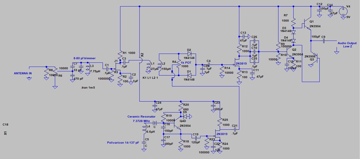
Complete Schematic


Sunday, January 21, 2018

Mike Rainey and Heavy Metal AM Phone

Michael Rainey AA1TJ wrote:  
I can tell you exactly what's going on here. I'd just received a license upgrade from "Novice" to "General." My new license granted radiotelephone privileges and I was eager to try them out.

In the early 1970's no self-respecting amateur radio operator would dream of using amplitude modulation (AM) on wavelengths above 10m. It wasn't illegal, rather, it was frowned upon due to bandwidth issues, among other things.
But in my excitement - and in the time-honored spirit of, "don't ask permission, ask forgiveness" - I tuned my clunky, Heathkit DX-100 to the 40m radiotelephone band and began calling CQ on AM. Everyone that I contacted was very polite, but to the man they all mentioned how "odd" it was to hear an AM signal on 40m. I eventually took the hint, but not before I'd figured out that yakking on a microphone wasn't my thing after all. Morse telegraphy was my first and enduring love.
-------------------------------------
I think Michael's next phone transmitter was that voice-powered rig that he used in an attempt to cross the Atlantic with the only power source being his vocal cords. But even there, he was using his voice to send Morse.  


C'mon back to radiotelephone Mike.  There is more to life than dots and dashes!

Saturday, January 13, 2018

SolderSmoke Podcast #202 Cover-Rig, SKN, Pete's Vector Boards, uBITX, K1BQT rig, MAIL

SolderSmoke Podcast #202 is available: 

http://soldersmoke.com/soldersmoke202.mp3

13 Jan 2018

Opening music from Shel Silverstein and Dr. Hook and the Medicine Show.  
On the Cover of the Rolling Stone or  On the Cover of SPRAT magazine.
Travelogue and Weather Report
-- Bill's trip to the Dominican Republic.  SWL on the beach.  Return to the ice box.  
-- Dramatic events in California. 

-- Reading Chinese Sci Fi with lots of radio in it.  "The Three Body Problem" by Cixin Liu

Straight Key Night.  IN QRP MODE THANK YOU.  With nephew Jeffrey.  Annual event -- worked Jim W1PID  friend of Mike Rainey.  

Steve Murphy and Jeff Damm on QSO Today.  FB. 

Oh your rig is homebrew?  "It must be propagation." 

ER Reading about G3UUR

Hams avoiding 60 meters due to 100 watt limit.  SAD. 

Bill's Bench:    Continuing series on the Ceramic Discrete DC receiver.   Described  the oscillator and the AF amp.  Next we will do the Mixer.   The most interesting stage. Nephew John Henry and niece Helena visiting today. 

Pete's bench.  uBITX adventures.   
The K1BQT IC transceiver. 
The Vector Board building technique.  See http://n6qw.blogspot.com/

MAILBAG
Paul KA5WPL  Looking for project with his son.  Sawdust.  Thanks again  Steve Silverman.

Chris Waldrup OM PBJ thanks for the gift

Pete in contact with Sven Johnson
Chuck KE5HPY sent us picture of fashion model with boatanchors in background  Grayson recalled 73 magazine covers...

Pete WB9FLW        Bilateral  SBE-33 ad  "with inherent stability"  That's the best kind!
Bruce KK0S experimenting with AF amps for the DC receiver

John KE5ETX Attempting CBLA


Saturday, January 6, 2018

Steve Murphy N8NM on QSO Today

Picture
It was really nice to sit back and listen to Eric's talk with Steve Murphy. 
Don't miss this one.  Listen here: 

https://www.qsotoday.com/podcasts/N8NM  

My notes: 

-- On  a Stingray bicycle patrol on garbage night, looking for radio parts.  FB Steve! 
-- Started with SWL.  A fine radio pedigree. 
-- Had an R-390A at age 16.  
-- Uses an LC meter to check on toroid windings. 
-- Steve:  Thanks for the kind words about inspiration. 
-- Manhattan And Ugly.    Mugly!
-- Planker!  Better on a Board!
-- Form Factor First, but then it never fits! Al Fresco! 
-- Packages arrive from China faster than they go across Israel. 
- - E-bay as a really good source for parts. 
-- Oh god, not an S-38E.  Stop torturing yourself Steve. 
-- N8NM: Radio Renaissance Man:  Runs a 2 meter repeater network.  Thinking of 900 MHz. 
-- Papa Legba -- I got it from a W9SCH via SPRAT.  He got it from Voodoo.
N8NM is chickenkiller.com   FB. 
-- Moderation?  Ha!  Good luck with that! 
-- An Electromagnetic Playground where Failure has No Consequences.  Well put. 

-Happy New Year Eric and Steve!  Thanks to  both of you. 

Straight Key Night at N2CQR


I did my part for the retro-Luddite-CW-Straight Key cause.   My HT-37 was kind of wheezing.  I may have to go in there to striaghten it out.  At times I had it cranked back to less than 5W (to maintain some semblence of QRP street cred). 

A highlight was the QSO with Jim W1PID.  Jim is a well-known QRPer and a friend of QRP Hero Mike Rainey.  Jim and I talked last year -- same date, same event, same rig. Jim has a really nice web site: http://www.w1pid.com/

My nephew Jeffrey joined me for the last two contacts.   He got a real kick out of it, both the CW and the SSB. 

31 December 2017
17S  P49MR   Martin – Back in the islands!  Like an annual QSO.
40CW  Pre SKN   W1PID on 40 with my HT-37. An annual event!  Jim running 75 watts
40CW SKN KF5RBR Dan in AR.
1 January 2018
40CW SKN W8HOG SKCC 87750 Perry in Ohio
40CW SKN N1CGP Dave in Maine using J37 key
40CW SKN WB4JJJ Al in Fairfax
40CW SKN K8SRB  Stan  in Ohio (with nephew Jeffrey with me)


17SSB WJ2N Andy in Florida (with Jeffrey in the QSO)

Monday, January 1, 2018

Jeff Damm WA7MLH on QSO Today


Happy New Year!    

There was so much wisdom and tribal knowledge in Eric Guth's interview with Jeff Damm WA7MLH. It was almost overwhelming. 

You should all listen to it.  Twice. At least twice: 

https://www.qsotoday.com/podcasts/WA7MLH
  
My notes:

-- I sympathize with Jeff's decision to go solid state and give up on high voltage after an encounter with an undischarged 600 volt capacitor.  
-- I really like the 1700 kHz IF with a 5 MHz VFO for an 80 and 40 meter receiver. 
-- Interesting that EE degree didn't help much in his efforts to understand ham gear.  Better to read Wes's books and Doug's. 
-- Tek Spectrum Analyzers were specially made to fit down a submarine hatch.  
-- Building and measuring just as important as studying the theory.  Inked-up text books. 
-- Learned ugly from Wes as a teenager. 
--Searched for old commercial gear to gut and use as homes for homebrew solid state gear. The enclosures,  panels and controls are very useful.   Great way to avoid metal work.  These rigs are no longer boatanchors!  Again, I sympathize.  I've sacrificed many Heath Lunchboxes and QF-1s.  
-- Jeff Builds the VFO first.  My preference too. But he understands Pete's AF-first approach. 
-- Finger on the input of the AF amp!  Buzz!  Yea! Step your way back to the front end.
-- ALWAYS one stage at a time.  
-- Osh Park Boards for standard circuit modules.  Like Legos. 
-- Cubic Feet of air variables.   Jeff has a lifetime stash.   
--Thinking about what was and should have been his section of EMRFD. Go for it Jeff. PLEASE! 
-- Hesistant about chips. Analog guy.  Would have been a huge time sink.  Analog guy.  
-- Buying parts on e-bay.  Fewer and fewer RF parts at hamfests. 
-- People reading QST Tech Articles for entertainment. Editor apprach: "Nobody will build it anyway." Handbooks giving priority to entertainment and less to information and education. 


Sunday, December 31, 2017

Ceramic DC Receiver on the Cover of SPRAT. Happy New Year to All! Straight Key Night.


G-QRP very kindly put my little DC Receiver on the cover of issue Nr. 173.   (Very sorry to see that GM3OXX has become a Silent Key. ) 

As we often say on the podcast, if you are not subscribing to this wonderful magazine, you are missing out on a lot of great ideas and circuits. Information on how to join the club and start receiving SPRAT can be found here: http://www.gqrp.com/join.htm   It is only 22 bucks! 

Reminder:  Straight Key Night is upon us.   It begins at midnight UTC 1 January.  It is a great way to begin the new year.  My HT-37 and my Drake 2-B are warming up now (and are helping to keep the shack warm on a very frigid day).   HNY to all!   73    Bill 


Saturday, December 30, 2017

Building the Ceramic Discrete Direct Conversion Receiver - Part 3 -- The Audio Amplifier


Once you have achieved JOVO and have the oscillator covering the frequency range you desire, it will be time to build the audio amplifier stage.  Now, I'm sure many of you will be tempted to just throw an LM386 or 741 op amp in there.  But don't do that!   You want to build the WHOLE receiver.  Don't let that IC manufacturer rob you of the FULL HB EXPERIENCE.

The DISCRETE amplifier circuit we will used is based on a design that several of us used to replace the LM386 in the BITX20 receiver. 


And here is a tutorial that does a GREAT job of explaining how this circuit works.  I strongly recommend you study the tutorial carefully.  This site will allow you to really understand how your amplifier works.  

It is not that complicated.  But here you have to take care to make sure that your amplifier does not turn into an oscillator.  Keep the outputs away from the inputs.  Keep the leads short.  Some planning is needed here.  Click on the picture below for layout ideas.  The right 1/3 of the board contains the AF amp circuitry. 


After you build the circuit, TEST IT!  If you have an AF signal source and a 'scope, great.  But if not, just hook some earbuds or headphones to the output, connect a 9 V battery and PLACE YOUR FINGER on the input of the first AF amplifier.  If you hear a noticeable increase in hum when your finger makes contact, congratulations, your AF amplifier is amplifying. 

The Complete Schematic

When you get this stage and the oscillator working, you are 3/4 of the way to completion.  Next we will built the mixer, and then the front end filter and amplifier. 

Thursday, December 28, 2017

Caribbean Beach Listening Post


Oh man, I wish I was still there.  It was 85F and very nice on Christmas Eve on the Eastern tip of the Island of Hispaniola in the Dominican Republic. I wasn't transmitting -- this time I was just doing some listening with my trusty Sony SW receiver.  But it did occur to me that the palm trees would have been EXCELLENT antenna supports. 


On December 24, 2017 around midday on 17 meter SSB I heard: 
NE2Q, NO4FR, IZ2LSR, N4DIR, PA1CC, N4LO, EA7JR, MI0TLG, VE1IOU, PA3WB, IU5FFM, KD4POK, HK2RMR, KB5VUM AND KG9DW   I was just using the little telescoping antenna that comes with the Sony. 
On December 26, 2017 also around midday I heard on 20 meter CW K8GL AND ZS1C. They were in contact -- I was located between them. 

I am now back in Virginia where it is 15F, dark and windy. 

Friday, December 22, 2017

The Three Body Problem by Cixin Liu

Strongly recommend this sci fi book.   Lots of physics


Some e!ectronics.  And even a bit of Morse.   Ask Santa.

Sunday, December 17, 2017

Building the Ceramic Direct Conversion Receiver Part 2 -- Building the VFO -- Our Goal is JOVO!

DC RX VFO and Buffer

I'll put the full schematic at the bottom of each of the posts so that you can easily refer to the big picture. Above you see the schematic of the VFO circuit. 

OK, here we go. Let's build the oscillator.  Our goal is JOVO -- the Joy Of Variable Oscillations. 

At this point you should have a big-enough copper clad board, and you should have given at least some thought to what kind of enclosure you are going to put the board in when you are done.  It pays to think ahead at least a bit, but don't get so carried away with planning that you never get around to building. 

You should plan the allocation of the space on the board.  Think about where you are going to place each stage.  You can mark out the spaces with a pencil or a Sharpie marker.  You might want to look at my board for ideas:     


In the picture above you can see the four stages.   On the left side of the copper-clad board you can see the Front end: the input filter and the RF amplifier (transistor near the top).  Moving toward the center you can see the mixer stage (around the circular 1k trimmer potentiometer).  Below the mixer (near the big round hole in the Bud Chassis) is the Variable Ceramic Oscillator stage and its buffer amplifier. The right 1/3 of the board is taken up by the audio amplifiers.  Note the use of Manhattan pads throughout.    Click on the picture for a closer look. 


Once you know where you will put the VFO, eyeball the schematic and think about where you will need Manhattan pads.  I often start by thinking of three rectangular pads for each transistor, one for each lead.  You can see that there are a lot of parts hanging off each of the terminals.  I sometimes put a long strip across the top or the middle of the board to carry the DC voltage.  

Since this is an oscillator, you don't have to worry too much about keeping the outputs away from the inputs.  You want this one to take of on you. 

For the feedback capacitors (C16 and C17) and the output capacitor (C19)  , get some ceramic disc NPO caps.  I put a 180 pf cap at C17 only becasue I didn't have a second 150 pf cap in the junkbox.  Either value will probably work. 

You will need a ceramic resonator.  I recommend this one from Mouser.  Again, buy a bunch.  They are cheap: https://www.mouser.com/productdetail/520-zta7.3728mt

You can, to start,  build this circuit WITHOUT the two components that allow you to vary the frequency: without L4 and C5.  Just run the left end of the ceramic resonator to ground. See below.  

Connect a 9V battery to the top of C24.  Without L4 and C5 (with one end of the resonator to ground)  you should be oscillating at around 7.168 MHz (the capacitors in the oscillator circuit are pulling the frequency down from 7.37 MHz).

You need some way to find out if it is oscillating.  If you have an oscilloscope, great.  Put the probe at the output and take a look.  But perhaps a simpler and more satisfying way to do this test is with a radio receiver.  Tune the receiver around 7.168 MHz.  You do not need to connect your receiver to the oscillator.  You should be able to hear it.  If you do, congratulations.  If not, check your work.  Be patient.  This is not plug and play radio! 

Once you get the thing oscillating, it is time to make it variable.  Here is an opportunity for variety and experimentation.  Here are some of the options you have: 


Here is what I found.   The frequency stability of these circuits vary.  But all of them are stable enough.  They might drift a bit so that you have to retune the dial every few minutes.  If that realy bothers you you can upgrade to the air core coil with air variable cap arrangement.  

When I put just a variable capacitor that goes from 17 pf to 159 pf between the ceraamic resonator and ground, I was able to tune the oscillator from 7.220 MHz to 7.420 MHz. 

If I put a fixed 8.18 uH coil between the ceramic resonator to ground that moved the frequency to 7.010 MHz.  You could use a toridal core coil for this, but I had best results with an air core coil.  By putting the 17-159 pf variable cap between the coil and ground (similar to the arrangement shown above) I could tune from 7.010 MHz up to 7.367 MHz. 

You could also replace the variable capacitor with a voltage variable capacitnce diode (aka a varactor or a varicap diode).    I had good results with an MV2301.   

You could try using a cheap little polyvaricon capacitor for C5, but my best results came with an air variable. Walter KA4KXX points out that nice variable capacitors are available here: 
https://www.amplifiedparts.com/products/capacitor-365pf-variable  If you can, get one with a reduction drive to slow the rate of tuning as you turn the shaft.  If you can't get one of these, try to get find a reduction drive to slow down the tuning. 

I ended up using a 3 uH air core coil with a variable cap of around 365 pf this allows me to tune from 7.115 MHz to 7.300 MHz (all of the phone portion of the band) with very good stability -- Juliano Criteria levels of Stability.  

One more idea:   As you build this stage, or right after you finish it, go ahead and build a dulicate circuit, perhaps without the variation components.  Why?  Well that second oscillator might be useful when it comes time to peak and tweak the front end input filter of your receiver.  And that second oscillator can become the start of a second version of this project. 

We talked about this project in SolderSmoke Podcasts #199 #200 and #201

Now I'm going to the beach.  I hope the holiday season bring you all joy -- especially the Joy of Variable Oscillations. Send us reports on your progress, your joy, or your tales of woe. 

The Big Picture

Saturday, December 16, 2017

Building the Ceramic Direct Conversion Receiver -- Part 1 Introduction, Stages, Parts.


I hope many of you decide to build this little receiver.  With it, you can break into the ranks of those intrepid ham homebrewers who have actually built a receiver.  Today I'll begin a series of blog posts on how you might do this.  Of course, there are many ways of proceeding.  I will describe my method.

FIRST:  ALWAYS look at this receiver as a collection of stages. Understand what each stage does and how they all work together.   Build it stage-by-stage.  Proceed to the next stage only after you confirm that the stage you just built actually works.

I see this receiver as having four stages:

1.  Front end  (RF gain control, input filter, first RF amplifier).

2.  Mixer

3.  Ceramic resonator variable frequency oscillator (and buffer)

4.  Audio amplifier (consisting of four transistors and associated parts).


In the picture above you can see the four stages.   On the left side of the copper-clad board you can see the Front end: the input filter and the RF amplifier (transistor near the top).  Moving toward the center you can see the mixer stage (around the circular 1k trimmer potentiometer).  Below the mixer (near the big round hole in the Bud Chassis) is the Variable Ceramic Oscillator stage and its buffer amplifier. The right 1/3 of the board is taken up by the audio amplifiers.  Note the use of Manhattan pads throughout.    Click on the picture for a closer look. 

I think you should build the oscillator stage first. 

What you will need:   In most cases, you shouldn't buy individual parts for this receiver.  I won't be providing a BOM.  Here is what I think you should do.  If you do not already have a good stock of electronic parts, start developing one.  Buy assortments of parts, or at least several of each part that you will need.  I use e-bay, amazon, mouser, digikey.   The parts are out there.

-- Get an assortment of resistors.  1/4 watt resistors will do.
-- Get a bunch of .1uF capacitors.  You will use a lot of these as bypass caps.
-- Get a bunch of 2N3904 and 2N3906 transistors. 
-- Get a bunch of 2N2222 transistors
-- Get a bunch of MPF102 and/or 2n2819 FET transistors.
-- Get an assortment of small electrolytic capacitors.
-- Get some Zener diodes in the 6-8 volt range. 
You will need some trimmer caps (8-80pf work fine).  Some 1K trimmer pots.  and some other stuff.

Get some copper clad board.  Pete suggest this, or something like it. 
https://www.ebay.com/itm/18-pcs-4-x-6-CEM-1-060-2-oz-Single-Sided-Copper-Clad-Laminate-Board-PCB/311756276147?ssPageName=STRK%3AMEBIDX%3AIT&_trksid=p2057872.m2749.l2649

Try to avoid the cheap fiber glass boards.   I prefer single-sided, but double sided is OK too. 

You will need to cut the board.  Get some tin shears.  Mine look like big strong scissors.  Use them to cut your boards to size AND to cut the little isolation pads for Manhattan construction.

Crazy glue.  I kind of like Gorilla Glue liquid (not gel).

Small wattage soldering iron.  35 W or so.   Get a small fan to keep the smoke and glue fumes out of your respiratory system.


   I used a piece of scrap wood to get the variable cap into position. 


Here it is with my fancy Archer Dial.  I used a bit of copper clad board to finish the front panel 
and to support the audio gain control. 


Next time I'll write about how you might build the Variable Ceramic Oscillator stage. 


Saturday, December 9, 2017

SolderSmoke Podcast #201 Santa, Storms, BUILDING A DC RX, SDR, uBITX


SolderSmoke Podcast #201 is available:  http://soldersmoke.com/soldersmoke201.mp3

9 December 2017

Santa Juliano

Forest fires, snow storms, and an earthquake. 

Santa arrives from Hyderabad -- uBITX in the house. 

Radio history.  First transtalantic amateur contacts. 

Bill's International Brotherhood Ceramic Discrete Direct Conversion Receiver Project. 
-- Goals -- Build your own receiver.  Really.  From scratch.  No cheating. 
-- How to get started.  Get parts and tools. 
-- Stage by stage. 
-- VFO first -- maybe build two. 
Bill built two already
-- Nephew is testing the first one. 
-- Polyvaricon limitations. 
-- Varactor limitations
-- Variable cap limitation.  
MEETING THE JULIANO STABILITY CRITERIA

Understanding the F5LVG mixer

Pete goes to the dark side with an SDR receiver. 
Pete's 800 Watt Amplifier gives him trouble. TRGHS. 

People in the News
Cliff Stoll -- Still Passionate about Electronics
Peter Parker -- VHF/UHF  By the Bay
Yardley Beers -- Early SSB with "The Black Rose"
John Kraus -- Moonbounce without the Moon. 

MAILBAG


Sunday, December 3, 2017

Discrete Ceramic 40 Meter Direct Conversion Receiver in Action (Video) -- BUILD THIS THING!


I've been holding off on making this video until I improved the stability.  N6QW is vigilent!  I only did this video after certifying that it meets the Juliano Stability Criteria.  I had to dispense with the polyvaricon and go with an air variable. 

We will be talking about this on the SolderSmoke podcast next weekend.  I hope to put on the blog  a stage-by-stage discussion of how to build this receiver.  

The dial from HI8P and the knob from a SW receiver that Elisa gave me definitely add soul to this new machine.  

JOIN THE RANKS OF THE TRUE HOMEBREW RADO MAKERS!  BUILD A RECEIVER!  BUILD ONE OF THESE!  

Saturday, December 2, 2017

Cliff Stoll -- Still Passionate About Electronics (Video)


I open Chapter 3 of my book "SolderSmoke -- Global Adventures in Wireless Electronics" with some quotes from Cliff Stoll:  "Where's the joy of mechanics and electricity, the creation of real things?  Who are the tinkerers with a lust for electronics?"  Well Cliff, that would be us! 

I'm glad to see in the (obviously) recent video that OM Still has not lost his passion for electronics. You guys will like this one.  Keep 'em comin' Cliff!

Friday, December 1, 2017

"The Black Rose" -- Yardley Beers' 1955 HB SSB Transceiver

I've been a fan of Homebrew Hero Yardley Beers W0JF for a long time.   Here is a link to previous posts on him: http://soldersmoke.blogspot.com/search?q=Yardley 
Yesterday I got a nice e-mail from Boulder Colorado about Yardley's very early SSB rig.  I'm guessing that the 4.7 MHz is a typo -- it might have been 3.7 and 14 MHz.   FB.  Thanks Mike


Bill,
 
Yardley Beers W0JF moved to Boulder in the early 1950's to work at the National Bureau of Standards (now NIST) laboratory.  There he headed the Time and Frequency Division, which maintains the atomic clock.  He later taught at the University of Colorado and Denver University.
 
About 1955 he homebrewed what, at the time, may have been the only SSB transceiver in the world.  It was built with individual transistors (no IC's in those days) and Yardley had to grind the crystals himself for the filter.  He enjoyed naming his radios and this one was "The Black Rose."
 
The transceiver ran at 4.7 and 14 MHz.  Its 1/2 watt output was fed to a home built amplifier.  The transceiver demonstrated the practicality and benefits of SSB in a world where AM was the voice mode.
 
In the year 2000 Yardley demonstrated this original, old SSB transceiver to the Boulder Amateur Radio Club by using it to make contacts with two club members.  Attached to this e-mail are a couple of photos.
 
73,
Mike W3DIF
Treasurer, Boulder Amateur Radio Club (BARC)


Thursday, November 30, 2017

VK3YE QRP by the Bay Goes VHF/UHF


Peter Parker again hosted the VK3 radio amateurs.  This time the event fell on VHF/UHF Field Day weekend.   So Peter and his friends went up in frequency and up into SPACE!  

VK3HN has a nice blog post here:

https://vk3hn.wordpress.com/2017/11/25/qrp-by-the-bay-chelsea-beach-melbourne-25-11-2017/

Be sure to read about Peter's ankle manacles -- he apparently uses them to get a good ground (sea) plane while running pedestrian mobile on the sea shore. Peter is DEDICATED! 

Wednesday, November 29, 2017

Listening for Your Own Signals on the Long Long Long Path


I heard some guys talking about this on 40 SSB last night.  A very cool use of the bidirectional pattern of the W8JK beam. 
From: http://qrznow.com/the-w8jk-is-a-famous-and-effective-dx-antenna/

Round-the-world paths The bi-directional nature of this antenna makes it possible to discover open round-the-world paths, something not possible with a normal beam antenna. The technique used by Kraus is to rotate the beam slowly, sending short Morse code dots, with a full-break-in or QSK transceiver. The delay time for the signal to return is about one seventh of a second, so there is plenty of time for your transceiver to switch to receive mode. When you have found and peaked an open round-the-world path, call CQ, and you may be rewarded with DX anywhere along the path. Also, the question of Long-path and Short-path does not arise – you are transmitting on both paths at once, giving you a greater chance of catching the other station’s beam direction….


Tuesday, November 28, 2017

Videos of iPhone Box DC Receiver


These are just a couple of short videos that I made for my nephew before sending him this receiver. 

As you can hear, deafness is not a problem with this design!   I did make some frequency stability improvements after this video was made -- I think you can hear a bit of drift.  Still, not bad for a very simple circuit using a polyvaricon superglued to the back of a cardboard box.  

I'll post more videos of the second version of this receiver.  There are further improvements in frequency stability.  My goal:  "Juliano Si5351" levels of stable-ness.  
Designer: Douglas Bowman | Dimodifikasi oleh Abdul Munir Original Posting Rounders 3 Column