Podcasting since 2005! Listen to Latest SolderSmoke

Sunday, September 29, 2019

W4AMV's Beautiful Receiver


Hi Guys,

We had our Knightlites annual BBQ this past Saturday. I wanted to share one of the radios from one of my Elmer's, Alan Victor W4AMV.
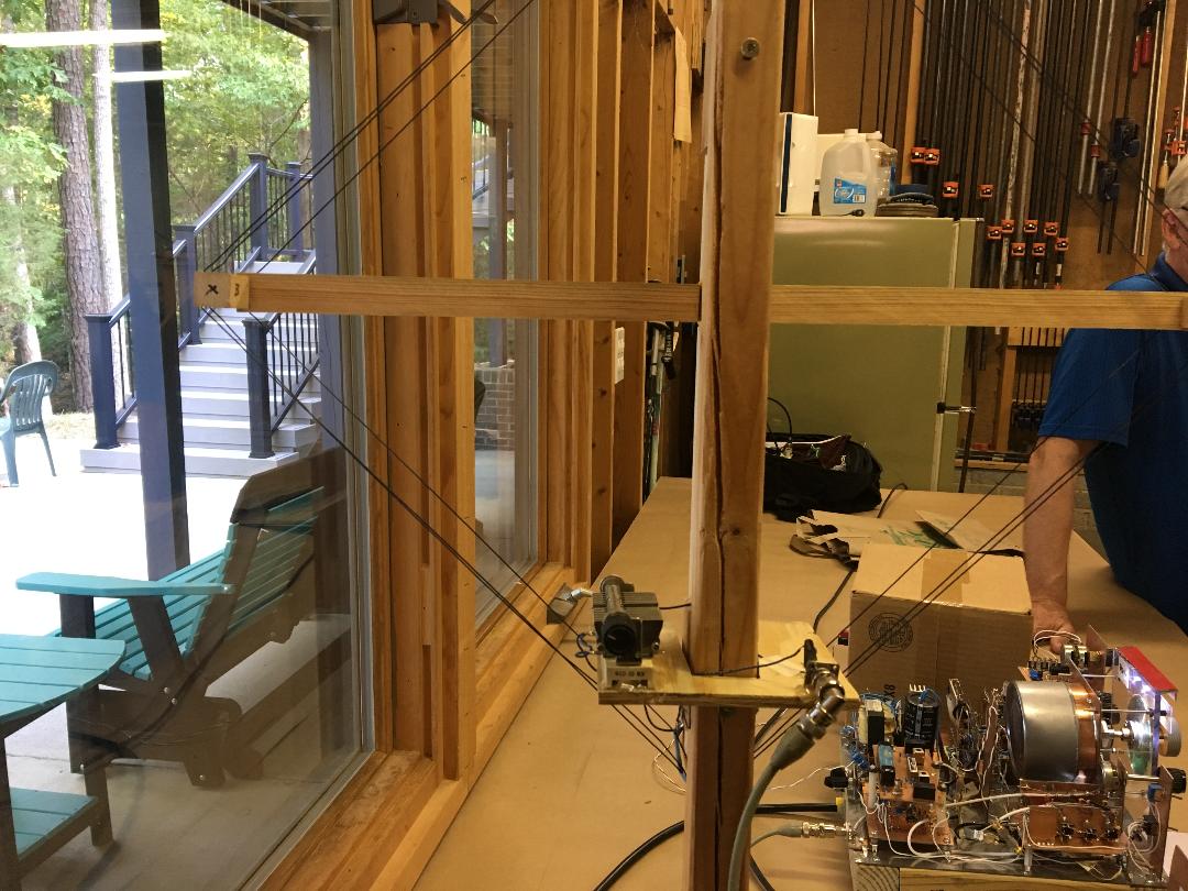
Pictured is him standing beside the preselector and receiver.
I hadn't ever heard a Collins mechanical filter vs Murata crystal filter side by side. The Collins was amazing. Single signal extracted from the band. The rig is line powered with a built in power supply.
There is a note (pictured) that has some specs.
Alan's work is to be savored, true analog engineering at its best. I wanted to share it with you.

Chris
KD4PBJ


-------------------------------------

FROM W4AMV'S QRZ.COM PAGE:


Here is a receiver that started out as a regen for the grandkids to copy code.
Digging through the junk box un convered parts that I forgot I had. Included a wide and narrow band set of filters. So, the unit wound up as a single conversion superhet. A fun radio to build as well to listen. The wide band filter provides super fidelity on sideband as well uncovers plenty of CW signals within a 10 kHz bandwith of the tuned frequency. A switch to either a 800 Hz audio filter or a 500 Hz CW filter permits focus on a single signal. I was going to package the whole unit, however I was prompted to leave it OPEN to show what makes it tick! 
Left side front is the RF preselector, mixer and pre amplifier with RF gain control. The rear double deck card is the IF and selectable wide and narrow band filters. The IF and pin diode IF gain control is bottom deck. The HF VFO is center stage with a 6:1 gear reduction. Right rear is power supply and voltage regulators. The active product detector and a BFO is just to the front of the power supply. The BFO is able to tune product detector output over a full 10 kHz of the IF. And finally the audio filter and 5 watt power amplifier. There is no AGC. Instead it is FUN to control every aspect of  gain control of the receiver; RF, IF and audio. Its a fun receiver to operate, dedicated to 40 meters and hopefully will spark the kids! 
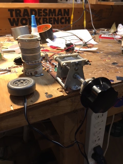
Going forward a receiveing station is setup to copy code. Although a nice long high wire would be proper, I settled on something a little more compact. A 40 meter small loop, 2 turns, about 18 inches on a side is connected to the preselector thru a pickup wire. This arrangement works quite well. W1AW will knock the speaker off the desk if your not careful. However, rotation of the loop to the E-W knocks down W1AW to a whisper. The pix shows the little 25 W infinity speaker in a 8x8x8 inch cardboard box, works well and the single conversion receiver sporting a new front plexiglass panel is illuminated for evening tuning. 


------------------------------------------------


Loop antenna used with the receiver


Saturday, September 28, 2019

Radio Art -- Zenith Tube Ad


This ad was recently shown on the K9YA Telegraph.  I was wondering about its origins.  I asked noted thermatron guru Grayson Evans -- he referred the question to fellow tube guru and author Ludwell Sibley.  OM Ludwell gives us the origins: 


She’s in a promo for Zenith, an Italian prewar brand that sold European triodes of types originated by Philips, and a few equivalents of American types.  She’s based on classical Italian art.  Doing a high-wire act while holding a small early-‘20s European           radio! I have an 11 x 17 glossy color print framed on the wail in the display room.  I ran       her as the cover art in a long-ago issue of “Tube Collector.”  “Three cheers for the red,       white, and green!"
Ludwell Sibley is the editor of "The Tube Collector."   Great stuff.  Their web site is here: 

Sibley's book "Tube Lore" can be purchased here: 

https://www.amazon.com/Tube-lore-reference-users-collectors/dp/0965468305/ref=sr_1_1?keywords=Tube+Lore&qid=1569660647&sr=8-1

Thanks Grayson, Ludwell, and to the K9YA Telegraph. 


Sunday, September 22, 2019

Pete Juliano N6QW on Homebrewing and SDR (Video)


Pete recently spoke to the Peel (Canada) Radio Club about SDR and homebrew.  The first 13 minutes show the club members but then it shifts to Pete.  Great stuff. 


Another Amazing Rig from VK3HN (Video) (EI9GQ Design)

Monday, September 16, 2019

ONE VOLT rms Reaches New Hampshire from Virginia

 My son Billy was back from college over the weekend (he came back to help me celebrate the completion of yet another orbit of the sun).  I was showing him my 8 part rig and telling him that it puts out 20 mW.  He asked a good question (he is a scientist):  What is the voltage at the antenna terminal.  I checked:  ONE VOLT rms.   About 1.414 volts peak.  Think about that.  My transmitter is sending a signal to New Hampshire from Virginia on less than the voltage of  AA battery.  

Two more spots on the Reverse Beacon Network (see above).  Another skimmer station in New Hampshire.  My signals seem to like the granite state. 

Sunday, September 15, 2019

Virginia to New Hampshire (one way) on 8 Parts and 20 mW


Having gotten the regen receiver portion of the ET-1 transceiver working nicely, I'm now working on the transmitter.  This is a much easier circuit to get going. (Check out the right hand side of the schematic below --- that is the transmitter.)  I have not made any contacts yet, but yesterday I called CQ on 7050 kHz and watched the Reverse Beacon Network to see if any of the skimmer stations picked me up.  Success!   W3UA up in New Hampshire received my signals. 

I was running about 30 milliwatts to my doublet antenna. The transmitter consists of EIGHT parts.  And three of them are the low pass filter. 

Next step:   Bring the transmitter and receiver together by using the switching scheme that OM Yingling used.  The RX and TX will share the same single FET (MPF-102 or J-310) with all three leads from the FET switched from TX to RX.   Then I will try for the elusive QSO with a single FET. 

More ET-1 related posts here: https://soldersmoke.blogspot.com/search?q=ET-1


Saturday, September 14, 2019

16x2 in Juliano Blue! The CRAP Single Board Transceiver by N6QW (VIDEO)


Another amazing rig and another very useful acronym from the wizard of Newbury Park.   

More here: http://n6qw.blogspot.com/

Saturday, September 7, 2019

SolderSmoke Podcast 213 WE'RE BACK!

N6QW's Analog CW QRP Transceiver
SolderSmoke Podcast #213 is available. 

http://soldersmoke.com/soldersmoke213.mp3

7 September 2019

The dire consequences of our summer absence. 

50th PODCAST WITH OUR FRIEND PETE! 
THREE CHEERS FOR PETE! 

Pete's Bench Report

-- Transceiver Count:  FORTY!  
-- SDR RADIGS 
-- Colorful OLED screens
-- Pilgrims and Paisanos -- "Left Coast Homebrew SSB"
-- Pete builds a CW transceiver (see picture above)


Bill's Bench Report: 

-- Going minimalist
-- Tuna Tin 2 + Herring Aid 5 = Fish Soup 7 (and later 10)
-- My QRPp QSO with K1PUB overheard in Canada
-- Glen Yingling's ET-1 
-- Bill attempting a single transistor transceiver

SPACE NEWS

-- Antuino's Cubesat Origins. Farhan's Antuino Mods
-- Apollo 11 Anniversary
-- Possibly the best space book ever:  "Carrying the Fire" by Michael Collins
-- Chinese microsat sending eclipse pictures from the moon
-- LightSail 2 success
-- India has spacecraft in lunar orbit. 

Eric Sears ZL2BMI and Dino Papas KL0S on "QSO Today" Podcast

MAILBAG: 

ZL2PD's Sugar Cube VFO
N8WQ gets free samples
N5RWF Getting started, wisely wearing beret
VK2EMU Australian Ad for Collins Filters
W1PJE on new LDMOS PA transistors
KA4KXX Al Fresco 75 meter SSB rig with model plane engine mufflers!  

Forgot to mention:  W9TH still has manuals for whover owns Drake 2-B #4215.  Check your serial number! 

Monday, August 26, 2019

Single Transistor Regen Has QSO Potential (Video)


In my previous blog post I'd expressed skepticism about using a single transistor regen on the air.  But over the years I've learned to give new receivers a chance.  They usually don't work perfectly on the first try.  You have to work with them.  It is almost as if you have to peak and tweak a lot in order to get them to properly inhale signals from the ether.  

That has been the case with this little receiver.  I found some silly mistakes in my construction.  And I decided to try some more sensitive headphones.  I ditched the 1000 to 8 ohm AF transformer.  And I added a very small variable cap for fine tuning.  

The results are amazing. See video above. It performs as well as most of the direct conversion receivers I've built. It is remarkably stable.  

I do think I could make contacts with this receiver.   I might eventually go the full ET-1 route and try to do it with a single switched FET, but I think my next step will be to built a single transistor crystal controlled transmitter on the same piece of wood, and try to make some contacts with a two-transistor rig. 

Wednesday, August 21, 2019

Another Bout of Minimalist Regen Madness

My success with the Fish Soup 10 QRPp transceiver got me interested in further minimalization.  About ten years ago I built a rig presented in SPRAT 108 as the ET-1 by Glen Yingling W2UW.   It re-appeared in modified form as the FETer by G3XBM in SPRAT 137.  

This rig uses just ONE active device, an MPF-102 FET that is switched via a 3 pole double throw switch from transmit to receive.  The transistor is switched.  The receiver is a regen and the transmitter is a very simple crystal controlled one stage oscillator. See: 
https://soldersmoke.blogspot.com/search?q=ET-1  for info on my ET-1 effort. 
The transmitter was the easy part.  I don't think I made any contacts with this thing.  That has been kind of bugging me.  

So I tried it again.  Again, I had trouble with the receiver.  So I looked around for another single FET regen receiver design.   I found one on AA7EE's page.  It was designed by N0WVA:  
https://aa7ee.wordpress.com/2015/02/07/n0wvas-one-fet-regen-optimized-for-ssbcw-sounds-great/


I've had a variometer in my junk box since about 1994. (Given to me by Pericles HI8P. QEPD.) It was time to use it as the coil and ticker for this rig.   I liked the green LED in the source, and the promise that this thing would not oscillate at audio frequencies.  

I built in on one morning.  See pictures. It works.  I can hear CW stations.  But I think I would have a tough time making contacts with this thing.   OM Yingling worked 24 states with his ET-1.  Respect.  


Tuesday, August 6, 2019

King Hussein JY1 Speaks to Owen Garriott on Shuttle Columbia


I thought this was a very nice contact -- the recording provides a nice bit of radio history.  I wonder how the German station got the JY1 portion of the QSO.

Saturday, August 3, 2019

Antuino Mods and Updates from Farhan


Both messages from the BITX20.io email group.

26 July 2019  

Peeps:


The Antuino has been in use for over a few months now. We had produced 100 of them that were sold at the FDIM. These work quite well for an SWR meter and Antenna Analyzer, but they were sub-optimal for serious RF work. For those who bought it for SWR measurements, you can continue to use it. For those who want to improve it, read on.

It was noticed that the db scale was not accurate. Antuino was designed to be an accurate and precise instrument. The db readings should be within +/- 1 db accuracy. However, they tended to vary by as much as 2 db on the upper range of power measurments. This was finally tracked down to having too much gain. I had prototyped the original with 2N3904 transistors but in production we used BFR93W as I guessed it would have 'better' performance. It turned to be a bad choice. The higher gain resulted in compression of signals above -30 dbm. This restricted the useful range of the Antuino to about 50 db. 

I am attaching the new (Version 2.1, it is a minor edit of the V2 that was sold at the FDIM). In summary, these are the changes:
1. The new software with a cleaner way to calibrate is on https://github.com/afarhan/antuinov2.1. Please upgrade to it even if you don't want to carry out the other hardware modifications.
2. Replace the Q1 and Q3 transistors to 2N3904. Although the PCB pads are SMT, you can solder the leaded type by twisting the legs around.
3. In the first IF amplifier (that immediately follows the mixer), we decrease the emitter resistor (R18) from 100 ohms to 51 ohms (you can also parallel a regular 1/4 watt 100 ohms with the original 100 ohms to get to 51 ohms). We also parallel the (R19) 220 ohms collector load with a 10 uh inductor (you can use 10 turns on FT 37-43), the exact value is not important.
4. In the second and third IF amplifiers, we replace the 100 ohms emitter resistors (R7, R34) with 10 ohms and remove the 4.7 ohm resistors (R32, R4).
5. In the last IF amplifier, we change the load resistor(R33) from 51 ohms to 220 ohms.

You need a few 10 ohms resistors and a 220 ohm resistor. You can resuse the R31 at R18.


Attached are the images and the circuit.

73, f 
_._,_._,_

August 3, 2019

Every instrument has limits on its accuracy. While making the Antuino, I was well aware of its deficiencies. 
I made a decision to keep it simple to a point where a radio ham could throw this thing together in an evening or two.

In order to overcome the limitations inherent in the Antuino design, the complexity could have been prohibitively complicated and expensive.
On the other hand, it is an extremely useful instrument that grows on you. I no longer use a frequency counter or the specan. I rarely use the oscilloscope. Antuino does most of my measurements.

There are two very important things you must be aware of while using the Antuino :
1. In the power measurement mode (the problem is non existent on swr or sweep mode), any reading above 25 mhz could be an image. Thus, if you see something at 35 mhz, you will have to do some mental math to figure out if it is not an image. An easy way to know is to add an external low pass filter with 25 mhz cutoff.
You have to use it like a radio in this mode. If you want to measure the harmonics from your pixie radio with 7040 crystal, tune to 14080, 21120, 28160 and measure. It is as accurate as any spectrum analyzer with more than 80 db of usable bandwidth. Raj and I struggled to get this for a month.
2. Unlike a full fledged spectrum analyzer, Antuino has just one bandwidth of about 7 KHz. This is enough to made IMD measurements at 20 KHz tone separation. The sweep plot does only 128 readings. Thus, if  you sweep a low pass filter from 0 to 20 mhz, it will measure the filter response every 120 khz. If there is something lurking between the steps, it will miss it. This is a common challenge with spectrum analyzers. So, a crystal filter should be swept at less than 100 khz. 
There is a software hack to mitigate this. First : introduce another control for step size. This can slow down the plot. A 30 Mhz sweep at 5 khz steps will involve 30 x 200 =60000 readings.It could take minutes. The Second : write a more optimal Si5351 routine that changes frequencies faster. I know that smaller jumps can be instantaneous on Si5351. I don't know that hack. If someone wants to take a stab at it, I am willing to work with them.

In a nutshell, Antuino is a very useful instrument. You don't have to buy it. You can build it. It is just as challenging as a direct conversion receiver. It does a fabulous job though. It can measure oscillator frequencies, it can measure amplifier gain, distortion, frequency response, it can measure filter response, it can show mixer behaviour, it can tune your antenna, it can measure power from a few uV to 100 mv and more with attenuators. It does all this slowly but surely. Like any precision tool, you must know its limitations and use them as an aware user. I would wager that if you have to choose just instrument for your lab, it would be this; Apart from a DVM.
And (I repeat) don't buy it, build it (grin)

- f

Designer: Douglas Bowman | Dimodifikasi oleh Abdul Munir Original Posting Rounders 3 Column