Just go to http://soldersmoke.com. On that archive page, just click on the blue hyperlinks and your audio player should play that episode.
http://soldersmoke.com
Don't get me wrong -- I'm a huge fan of Doug DeMaw. His books and articles are a treasure trove for ham radio homebrewers. Also, Doug was an honest guy who admitted in the preface to his QRP book that at times he did not fully understand the circuits he was building; that kind of honesty is rare, and is very helpful to amateurs who struggle to understand the circuits we work on.
But everyone makes mistakes, and Doug made one in his "W1FB Design Notebook." I present it here not as a "gotcha" effort to nitpick or sharpshoot a giant of homebrew radio, but because this error illustrates well the depth of the 75 LSB/20 USB myth, where it comes from, and how important it is to really understand sideband inversion. Here is the mistake:
That's just wrong. A receiver built like this will not allow you to listen to 75 LSB and 20 USB "without changing the BFO frequency." (Am I the first one to spot this error? Didn't anyone build this thing, only to discover that it, uh, doesn't work?)
Here's a little drawing that I think illustrates why the mythical scheme will not work:
All confusion about sideband inversion could be avoided with the simple application of what I think we should call "The Hallas Rule":
"Sideband reversal occurs in mixing only if the signal with the modulation is subtracted from the signal that isn't modulated."
Be careful here: I think some arithmetic carelessness is responsible for much of the myth. Taking the difference frequency is not enough to produce sideband inversion. Read the Hallas Rule carefully: For sideband inversion to occur, the signal with the modulation must be subtracted FROM the signal without the modulation.
---------------------------------------------
About the Swan 240's SSB generation scheme:
I first stumbled on this problem when building my first SSB transmitters in the Azores. I was using a VXO, and a filter pulled out of a Swan 240 (5.173 MHz). I started with VXO crystals at around 12.94 MHz. The rig worked, but I couldn't pull the VXO crystals very far. So I switched to crystals at around 23.3 MHz (you can pull higher frequency crystals farther). But look what happened: My Carrier Oscillator frequency had been set up to receive USB signals on 17 Meters. With the 12.94 MHz rocks, that worked fine: 18.150-12.977 = NO INVERSION. But it all changed when I went to the 23 MHz VXO rocks: 23.323-18.150 = INVERSION! This had me scratching my head a while. I had to draw myself little spectrum pictures (like the one above) before I realized what had happened. To get it to work -- to get it to produce USB on 17 meters -- I had to move the Carrier Oscillator to the other side of the passband. Good thing that Swan 240 came with TWO BFO crystals (5.1768 MHz and 5.1735 MHz). I just had to change the crystal.
For 75 and 20 meters, the Swan 240 uses the correct 5.173 MHz filter with a 9 MHz VFO to get the happy situation of 75 meter LSB and 20 Meter USB WITHOUT changing the BFO/Carrier Oscillator frequency. This is the Mythbuster scheme. Unlike Doug's receiver, it works. The scheme also works in the Swan 240 on 40 meters because for 40 the Swan rig has the VFO running from 12.073 MHz to 12.513 MHz. Here too, no change in the BFO/Carrier Oscillator frequency is needed. But the Swan recommended a modification that would allow operation on 20 LSB and 75/40 USB! It used a BFO/Carrier Oscillator crystal of 5.1765 MHz and a switch mounted on the front panel. Luckily, my junker Swan (acquired from HI8P in the Dominican Republic) had the second crystal -- mine was 5.1768 MHz. It was that crystal that allowed me to get my Azorean SSB transmitter to work using the 23.9 MHz VXO rocks.
I like to listen to the Old Military Radio Net on Saturday mornings. This week I was listening with the Mythbuster receiver. The AM carriers provided a good opportunity to observe the effects of the steep skirts of the 10 pole crystal filter. We start at zero beat, with the BFO exactly on the carrier frequency. If I turn the VFO dial in one direction, I in effect move the passband in a way that puts the carrier in the passband. And it is no longer zero beat with the BFO, so we hear the heterodyne (the beat!). But if I turn the VFO dial in the other direction, the carrier is now outside the passband. Even though the BFO would produce a tone, we don't hear a tone, because those steep filter skirts are keeping the carrier out. We do continue to hear some of the sideband frequencies, because they remain in the passband. The very sharp drop-off of the carrier tone is a good indication that the steep skirts of the crystal filter are doing the job.
"Zero Beat and the Vertical Skirts" Sounds like the name of a Punk Rock band, doesn't it?
Anyway in this video I explain what happened in Mythbuster Video #8 (above). I explain why we can hear the Old Military Radio Net carriers when I tune the VFO in one direction, but not in the other.
Better than anyone else ever has, Michael Hopkins, in his fictional series about Frank Jones and the Five Meter Liberation Army, captures the spirit of homebrew radio. There is just so much of us in those articles. I read them some 20 years ago when they first came out; reading them again recently I appreciated them even more.
Frank was a bit of a curmudgeon: There are jabs at the appliance operators, Hiram Percy Maxim, hamfests, SSB, the Collins collectors, the QRP movement, and even Electric Radio magazine. Howard Armstrong makes an appearance, as do Carl and Jerry. It all made me want to put a five pin SAW filter on my lapel.
As I read, I thought about what a great writer Michael was. When I Googled him, a few of the results led me back to my own book. I'd forgotten that Michael was in there, but he is. On one page he advises me how to power my Mate for the Mighty Midget receiver without using a power transformer (a very Frank Jones approach). On another page I note that Michael had sent me a kit for the Doug DeMaw "Barbados Receiver." Wow, that was my first Superhet. (I also have one that was built by Dale Parfitt.) Most of the parts were put to use in other projects. But I still have the board (see above). Reminded that it came from Michael, I will now have to complete the construction.
Below is a nice article about Michael that appeared in the Flying Pigs newsletter. (Click on the images for an easier read.)
Alan Wolke W2AEW is a true wizard. We are all lucky to be interested in homebrew radio at the same time that he is sharing his knowledge and wisdom via YouTube.
The ability of the NanoVNA to measure circuit impedances is, in my mind, one of its most valuable features. With this, we can MEASURE input and output impedances. We can put bits and pieces of circuitry together without wondering whether or not we were introducing impedance mismatches.
But I had trouble getting good NanoVNA impedance readings on my TIA amps. I wrote to Alan about this and he pledged to make a video about how to do it right. That video was posted to YouTube today (see above).
Not only did I learn how to get a good impedance reading, I really learned a lot by just watching Alan move around through the various NanoVNA screens. I want to be able to do that too! I want to monitor the Smith Chart, and gain, and SWR, all at the same time. Yes I do! I also now realize that I have to order a bunch of those cool PC board SMA female connectors from Bezos.
I have the speaker mounted on the front of the board. I kind of like it like that. I now have a bandswitch, and reverse polarity protection (no more living dangerously for me). That Yaesu VFO clarifier circuit might prove useful should I decide to give this rig CW capability. I once again find myself thinking that I might never put this in a metal box. Frank Jones had the right idea.
Here's how I started with the Elsie program. Note that to get a 50 ohm match on both ends it needs an impractically low value for the coils (.064 uH).
But Elsie lets you specify the coil value. So I then I went with 1 uH. But with this value you don't get 50 ohms at either end. You need a matching network. Elsie provides this too!
I asked Elsie to match my BP filter to 50 ohms. It provided several options to do this -- I went with a simple capacitive impedance divider. But alas, I was now bumping up against the 7 limit of the free version of Elsie so I had to reduce the number of LC elements from 4 to 3. Bummer.
With 3 LC tuned circuits and matched to 50 ohms the plot looks OK. But I would have preferred 4 LC circuits.
The rftools website created a BP filter for me with 4 LC elements, and matched to 50 ohms. Very useful. https://rf-tools.com/lc-filter/
But here's my problem: With both the filter designed by Elsie and the one designed by rftools, I found that the filter passband was too low. It was in the 12 - 13 MHz range. I found that by removing 3 turns from the 1 uH coils I could move the passband up to the desired range. But why the discrepancy? I was measuring the coils and the caps with an AADE meter. I was testing the passband both with a NanoVNA and with a combination of an HP8640B sig gen and a Rigol oscilloscope (with the filter terminated into a 50 ohm resistor). Any suggestions on why these filters should have passbands lower than predicted would be appreciated.
This receiver required almost no coaxing or tweaking, probably because I had been so careful about testing and measuring each of the stages.
I have been pleasantly surprised at how well the receiver works without an RF amplifier ahead of the first mixer. But I need to know how much AF gain I have in order to understand how/why the entire receiver works so well. I think I have about 35 db of gain (combined) through the two TIAs and the crystal filter. That would mean that all of the remaining gain is provided by the AF amplifiers (with some loss in the product detector). I haven't really measured the gain of the AF preamp/LM386 combo, and I had some trouble measuring the input impedance of the pre-amp with the NanoVNA.
The 75 meter LC filter to the left of the VFO is actually a bandpass filter, not the lowpass filter. And what I call "the mixer" to the right of the VFO is really the Product Detector/BFO.
For the 75 meter bandpass filter, I used the ELSIE program.
75 meter Bandpass Filter designed in Elsie. 10 turns on a T50-2 toroid yield .46uH.
Here's the plot from Elsie on the 75 meter BP filter.
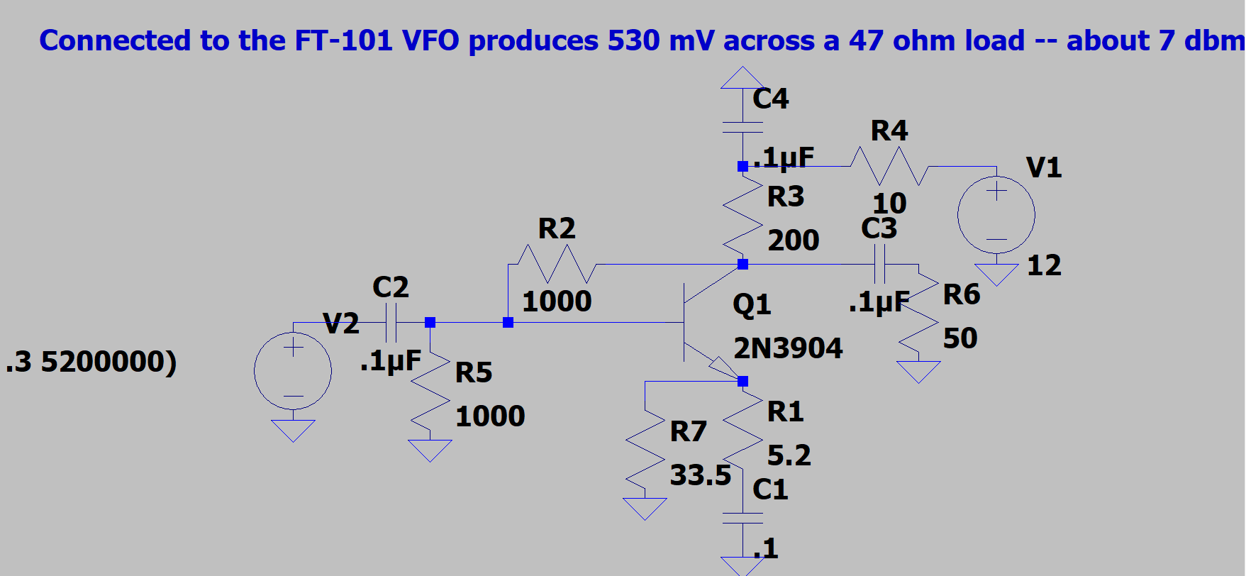
Alan W2AEW asked for a picture of the VFO output.
On this shot I had the probe between theVFO and the
outboard booster amp that I built to bring it to 7dbm.
I used LTSpice and Wes's FBA program (from LADPAC) to come up with a circuit that would provide the needed gain. I needed to get the 290 mV rms signal (across a 50 0hm load) up to the 500 mV rms signal needed by the ADE1 mixer. Above is the amplifier that I came up with. The key here is to adjust R2 and R1 to get the required gain.
This is a 5.2 MHz crystal filter. I used the G3UUR method for determining the crystal's motional parameters. I then used Dishal and AADE software to design a 10 pole Cohn Min-Loss filter. I tested the bandwidth with an Antuino Scalar Network analyzer (thanks Farhan!) and a NanoVNA. I found the passband to be a bit tight for SSB, so I replaced the capacitors with caps of a slightly lower value -- this broadened the passband. It is still a bit tight, but the SSB audio -- while not enhanced or Hi-Fi -- sounds fine.
Passband filter shape as seen in the Antuino and in the NanoVNA. The -20 db line in the Antuino actually corresponds to no loss.
The schematic provided by the AADE software. Dishal software may have come up with better, more correct values for the capacitors.
The passband as predicted by AADE. Skirts so nearly vertical as to strike fear in the hearts of SDR owners!
Filter under construction -- waiting for the caps from Mouser.
First scan with the NanoVNA. Insertion loss looks very high but that is only because I am terminating the filter with resistors -- I just wanted to see the passband shape.
I am happy to report great progress on the Mythbuster project. I have the receiver working on both 75/80 and 20 meters. And it in fact inverts the 75 meter LSB signals, turning them into 5.2 MHz USB signals for passage through my 5.2 MHz USB filter/BFO combo. No switching or shifting of the BFO is needed.
I am following Farhan's BITX20 advice -- I have paused in the construction and am enjoying the receiver that I have built. I'll build the transmit circuitry later.
Inspired by Frank Jones (you really should be reading the FMLA articles) I have this rig prototyped "Al Fresco" on a pine board that I found discarded on a neighbors front stoop.
There is no RF amplifier in this rig. Following the advice of multiple receiver gurus, I ran the BP filters right into the ADE-1 diode ring mixer. I have the TIA amps set at about 24 dbm. There is a lot of audio gain from the LM386 and the audio pre-amp. This seems to be enough, even on 20. I hear the band noise when I connect the antenna on both 75 and 20.
Here is the first video in the series. I'm posting them first on Patreon, then, a few days later, here and on the YouTube channel.
The narrator was in CW contact on 6 meters with a guy who turns out to be... Frank Jones.
----------
I threw the switch on my AEA keyer and sent the station description while I deciphered my notes. When the keyer signed, Frank said: QSL THE COMMERCIAL GEAR - EVER THINK OF TAKING UP AMATEUR RADIO? QRQ?
I really hope Ciprian can get a license very soon. His homebrew projects alone should qualify him. Ciprian has The Knack. It would be great if the IBEW (especially the European branch) could help Ciprian get some more parts and test gear.
Tony G4WIF sent me this video from Nick M0NTV. It presents Nick's latest Bread Bin project -- "The Optimizer."
-- I really like the Bread Box enclosures. And leaving the b and the d on the box is just brilliant. These letters now stand for BiDirectional! They even appear symmetrical. TRGHS!
-- The switch for a tuning tone is a great idea. I still have to plug my Maplin AF sig gen into the mic jack to do this. FB.
-- I too have the connector on the back for keying the outboard linear amplifier. (Shhh! Don't tell G-QRP!)
-- As for the bidirectional TIA amps. I'm really glad that someone else is using these circuits. Wes's article came out in 2009 and concluded with a call for someone to build a complete rig with these circuits. I wonder how many rigs like this have been made. It is a great circuit. One thing I would suggest for Nick: Wes's article points out that you CAN have higher gain in one direction than you have in the other. Just use resistor values in the chart provided in the 2009 article. You could have an amp with 15 db in the transmit direction and 24 db in the receive direction. BTW: I have been getting a lot of help from Alan W2AEW and Farhan VU2ESE on how to use the NanoVNA to confirm the input and output impedances on solid state amplifiers.
-- For many years I had the same map of the Moon in my shack. I hope that map makes it to the new house Nick.
-- Finally, I was really surprised to hear EI0CL calling CQ during Nick's demo of the receiver. That is Michael Higgins out in Galway. Michael was one of my regular contacts when I was out in the Azores. He is a truly amazing guy. He is mentioned frequently in my "SolderSmoke -- Global Adventures in Wireless Electronics" book. TRGHS.
I read these stories when they were first coming out and I really liked them. Here are all the FMLA episodes. Don't try to read them all in one sitting. Spread them out. Savor them. Think about the message that Frank was sending us.
"SolderSmoke -- Global Adventures in Wireless Electronics" is now available as an e-book for Amazon's Kindle.
Here's the site:
http://www.amazon.com/dp/B004V9FIVW
April 22, 2024. Did you miss this Subtlety?
-
*Our 12MHz IF Amp plot out to 100MHz *
In yesterday's posting I shared a 9MHz IF Amp using the J310's configured
as a Dual Gate MOSFET. Soon...
The POTA Babe Goes Back to Florida – Day 3
-
Day 3 of my spring-break Florida POTA trip began well. Those of you who
read my “A Confession from the POTA Babe” article know my personal life has
been an...
An Inline RF Step Attenuator for QRPp Work
-
I don’t need to explain the attraction of low power operation; if you’re
reading this, the chances are that you are already a convert. I’ve been
operating ...
Using an external clock with the RX-888 (Mk2)
-
*The RX-888 (Mk2) and external clocking*
*Figure 1:*
The RX-888 with external clock input *(right)*
The enable/disable switch is barely
visible behind the...
A 51S-1 Restoration Story
-
I came across my Collins 51S-1 in a big junkyard in Ankara, Turkey around
2012. It was in a pile with a lot of other electronic scrap, probably from
one o...
New QRP Cluster Online From OM0ET and OM6APN
-
By DX EXPLORER
DX EXPLORER
Paul OM0ET and Peter OM6APN recently launched a new cluster dedicated to
QRP operations. Have a look and I hope you will enjoy...
3D Printing The Hadley 114mm Newtonian Telescope
-
Yes, we’re building a 3D Printed Newtonian Telescope called Hadley. It’s
being printed in PETG and in the video below, I give a quick tour. My build
isn’...
3D printed project boxes
-
I have been busy with some other things that have kept me away from
electronics projects for quite a while. Now I can get back to them, but
realize I n...
Daylight Again – An all Analog Radio
-
What’s all this? In 10 seconds, A high performance, 7MHz, 5 watt SSB rig
Draws just 24 mA of current 90 dB dynamic range, 80 dB close-in dynamic
range 3D ...
Adding Enclosure to your sBitx Boards Order
-
The early buyers of the sBitx board set who bought it for $270 USD might
want to also add the enclosure (box) for in the kit. What you will now get
is a f...
Digi-chirp! Digital synthesis of ‘nostalgic’ CW
-
The bottom ends of 80, 40 and 20m are not what they used to be. For
starters, the busiest part is the digital segment where computers talk to
computers – l...
-
A Simple Speech Processor
(For QRP/SSB Homebrew Transceivers )
Over the last few weeks I had been thinking to build a small AF speech
processor to add to...
A New Look for your uBitx!
-
Adding a "Cool Blue" Display to your uBitx!
The standard "green background" with black lettering frequently reminds me
that I suffer from Chronic seasickn...