Podcasting since 2005! Listen to Latest SolderSmoke

Tuesday, November 30, 2021

Putting a Barebones Superhet on 17 Meters with an NE602 Converter (Video)


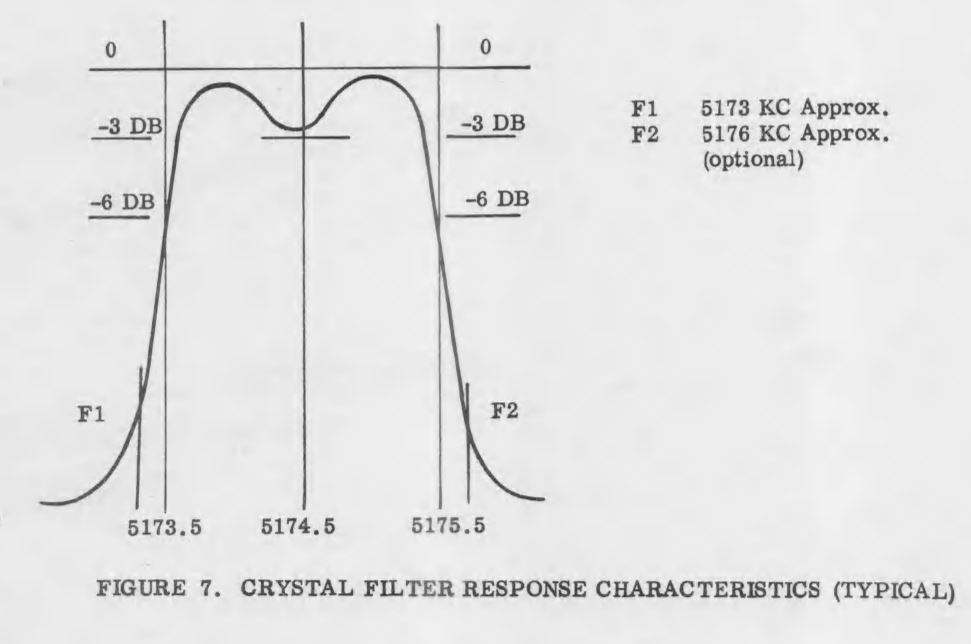
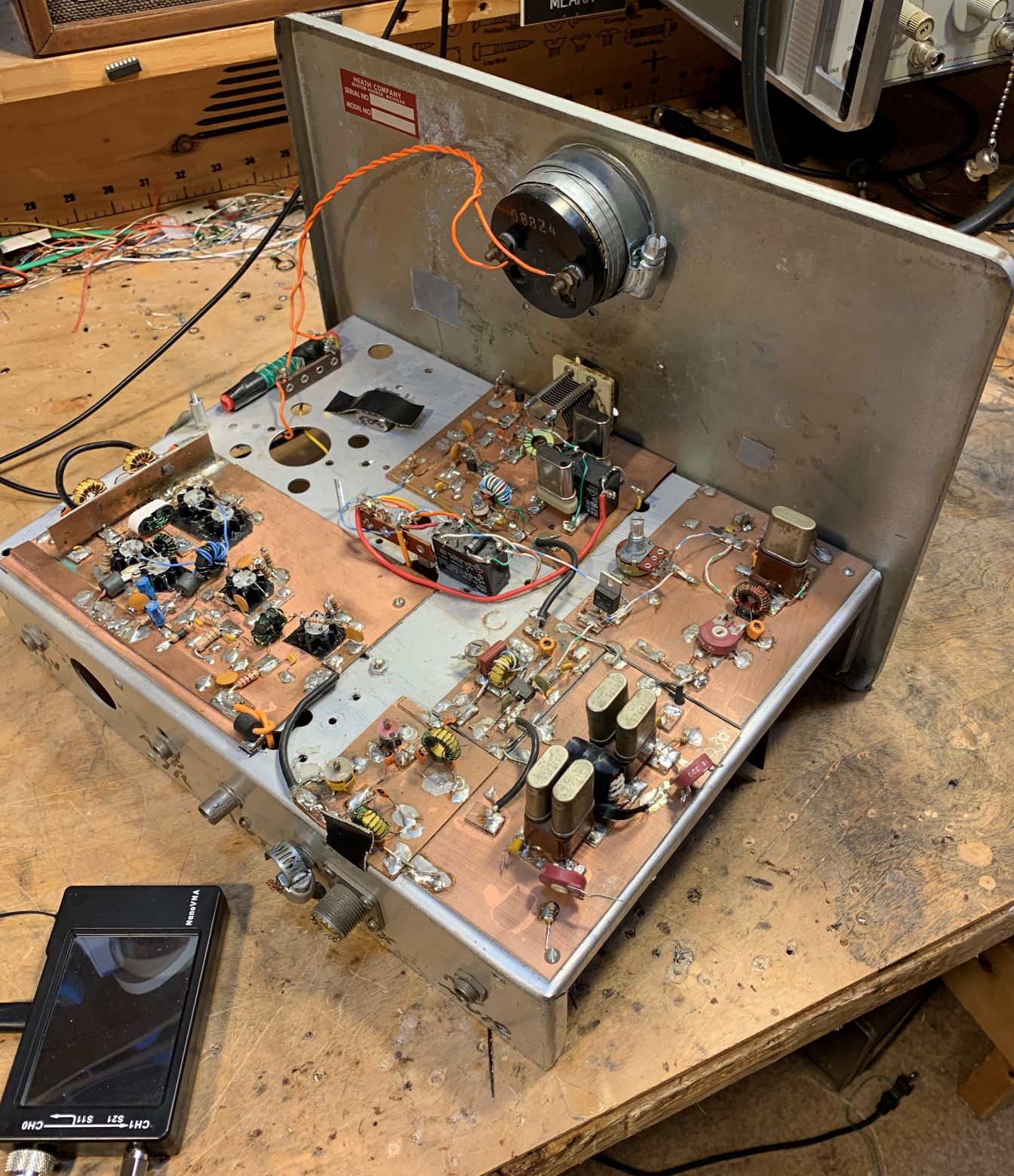
Armed now with a NanoVNA, I took a look at the passband of the 5 MHz filter in my Barebones Superhet (BBRX)  W4OP built it on a Circuit Board Specialist Board.  He put a 5 MHz CW filter in there;  I broadened the passband for phone by changing the values of the capacitors. Here is what the passband now looks like in the NanoVNA: 


This is what DeMaw would call an "LSB filter."  You would get much better opposite sideband rejection by using it with an LSB signal, placing the BFO/Carrier Oscillator slightly above the passband, in this case near 5.002 MHz. 

When I first built the down converter to get the 18.150 MHz signal down to the 7 MHz range (where I had the receiver running) I used an 11 MHz crystal for the NE602's local oscillator.  But this created a big problem:  18.150 - 11 =   7.150 MHz.  That is in the 40 meter band, but note:  NO SIDEBAND INVERSION.   Then in the BBRX  7.150 MHz - 2.150 MHz = 5 MHz  (the filter frequency) but again:  NO SIDEBAND INVERSION.   The signal started as a USB signal and remained a USB signal. 

I briefly tried shifting the BFO frequency to the other side of the filter passband.  If I could get it to around 4.985 MHz, it might work, but because the filter passband was so large, and because the crystal frequency was so low, I was unable to shift the crystal frequency that far.  In any case the results would have been less than ideal because of the "LSB" shape of the filter.  Back to the drawing board. 

I decided to cause one sideband inversion. 

At first I put a 25.175 MHz crystal module in my down converter.  This shifted the 17 meter phone band down to the 40 meter CW band.  It worked, but I cold hear strong 40 meter CW  signals being picked up by the wiring of the receiver (the box is plastic!).  I went back to the module jar in search of frequency that would move 17 meter phone to the 40 meter area (so I would not have to re-build the BBRX front end) but outside the actual 40 meter band.  

I ended up using a 25 MHz crystal in the down converter. 25 MHz - 18.150 MHz = 6.85 MHz WITH SIDEBAND INVERSION.  After checking on the NA5B Web SDR to see that there are no strong signals in the 6.835 to 6.89 MHz range, I retuned the output circuit on the converter and tweaked the input capacitor on the Barebones.  I shifted the VFO frequency down to 1.835 to 1.89 MHz and put the BFO at 5.002 MHz.   The receiver was inhaling on 17 meter SSB.  

One more change to the BBRX:  in his June 1982 QST article, DeMaw warned that trying to get speaker level audio out of the 741 op amp that he used would result in audio distortion.  And it did.  So I put one of those little LM386 boards I have been using into the BBRX box.  I just ran audio in from the wiper of the AF gain pot.  It sounds good.  

In effect this is my first double-conversion receiver.  I usually prefer single conversion, but this project has highlighted for me one of the advantages of double conversion for someone like me who eschews digital VFOs:   Starting with a crystal filter at 5 MHz,  with double conversion I could keep the frequency of the LC VFO low enough to ensure frequency stability.  That would have been impossible with a 5 MHz IF in a single conversion 17 meter rig.  But if I were starting from scratch for a 17 meter rig, I could stick with single conversion by building the filter at 20 MHz,  keeping the VFO in the manageable 2 MHz range. 

Now, on to the SSB transmitter.   The Swan 240 dual crystal lattice filter from the early 1960s needs some impedance matching. 

Sunday, November 28, 2021

How To Understand the NE-602 and the Gilbert Cell Mixer


I think the key to understanding the Gilbert Cell Double Balanced mixer is to separate out the three tasks that this device completes, and consider them one at a time, using different diagrams: 

1) It mixes two signals to produce sum and difference outputs. 
2) It balances out the RF input. 
3) It balances out the LO input. 

                                                                  Task 1 -- Mixing


The Gilbert cell is like the diode ring mixer in that it switches the polarity of the input signal at a rate set by the Local Oscillator. Another way of saying this is that the mixer multiplies the input signal by 1 and by -1. 

Steve Long of the University of California described the essence of this mixing this way (using the diagram above): 
 
An ideal double balanced mixer simply consists of a switch driven by the local oscillator that reverses the polarity of the RF input at the LO frequency.  http://literature.cdn.keysight.com/litweb/pdf/5989-9103EN.pdf

In an effort to see this for myself, I drew (noodled!) this diagram: 


There are four transistors -- two differential pairs with RF coming into the bases of the pairs. 
The LO is a square wave.  The LO alternately turns on transistors 1 and 4, then 2 and 3.  When 1 and 4 are on, we are in period 1 -- here there is no switching of polarity.  Portions of the RF waveform are passed to the outputs.  But when the LO turns on transistors 2 and 3, portions of the RF wave form are "crossed over" to the opposite output.  Polarity is reversed.  We see this in period number 2. 

Take a look at the resulting output waveforms.  This is the same waveform we see coming out of a diode ring mixer.  I really like this drawing because in that complex waveform you can actually see the sum and difference frequencies: 


I could see this diode ring waveform myself on my oscilloscope: 


TASK 2 -- Balancing Out the RF Input 

In a diode ring, and in other diode mixers, the balancing out of the input signals really takes place in the trifilar toroidal coils that are part of the circuit.  Barrie Gilbert needed an integrated circuit mixer that did not use coils.  


Again referring to the above diagram, Steve Long of the University of California put it this way: 

The ideal balanced structure above cancels any output at the RF input frequency since it will average to zero.

To fully understand this I find it helps to look at the Gilbert cell circuit drawn in a different way.  Here is a drawing from Alan Wolke W2AEW that I found very helpful. It comes from his excellent YouTube video: https://www.youtube.com/watch?v=7nmmb0pqTU0


Suppose the RF waveform at I1 is causing the current through R1 and R2 to increase.  At the same time, the opposite phase current through I2 will be causing the current through R1 and R2 to DECREASE.  So there is no net effect of the RF signal at the output.  The RF is balanced out. 

TASK 3 - Balancing Out the Local Oscillator Signal 


Here too I used my own drawing, and was guided by the words of Steve Long: 

It also cancels out any LO frequency component since we are taking the IF output as a differential signal and the LO shows up as common mode.  

The important thing to realize here is which transistors are being turned on and off by the local oscillator signal.  On one half cycle of the LO, transistors 1 and 4 are on.  So  the LO signal at the LO frequency are both pulling the same amount of LO frequency current through the resistors. So you have the same change in voltage at the output terminals.  And the output terminals are differential.  The LO signal results in no voltage difference between the terminals.  So the LO frequency is balanced out. 

The same thing happens on the following half of the LO cycle.  Here, transistors 2 and 3 are turned on. Again, both transistors pull the same amount of LO frequency current through the resistors. There is no differential voltage.  So no LO frequency energy passes to the output.  LO frequency is balanced out. 

--------------------------------

I am surrounded by Gilbert Cell Mixers and I have been using them in my homebrew rigs for many years. I use them in up-converters for my RTL-SDR receivers.  I have one in the downconverter for my 17 meter receiver and had one as the mixer in my first SSB transmitter. I built a 40 meter SSB transceiver with NE602s on either end of the crystal filter. Years ago, I built a DSB transceiver with several NE602s.  My SST QRP CW transceiver is made with NE602s. I have on my bookshelf Rutledge's book "The Electronics of Radio" that is all about the NORCAL 40 transceiver, built using NE602 chips.  But until now I really didn't know how these chips worked.  Truth be told, for me they were mysterious little black boxes, and that bothered me.  Now I feel a lot better about using these clever devices.  I plan on stocking up on the old style (non-SMD) NE602s.  

Apparently Barrie Gilbert rejected the idea that he invented the circuit that bears his name.  It seems that Howard Jones first used this circuit in 1963, with Gilbert developing it independently (in an improved form) in 1967. 

 Barrie Gilbert was quite a guy, with electronic roots in the world of tinkering: 


Saturday, November 27, 2021

The Galway Radio Experimenters Club


My old friend Mike EI0CL used to remind me that hams in Ireland are granted not just an amateur radio license, but an amateur radio experimenter's license, with an emphasis on experimentation. I think we can see that emphasis in the newsletter of the club.  It has a remarkably high level of technical content.  Check it out, and look at more information on the club: 


Here is their latest newsletter: 

Pete N6QW's PSST rig is mentioned on Page 4 of the Winter 2021 edition. TRGHS. 

Thanks to John EI7GL for alerting us to this gem via his FB blog

Wednesday, November 24, 2021

Gloria -- A Netflix Series about a Shortwave Broadcast Station in Portugal


Rarely if ever will we come across a high quality NETFLIX series built around a shortwave broadcast transmitter.  But that is what we have in Gloria.    It is really good.  We were especially interested in it because we lived in Portugal for three years. In addition to all the intrigue and drama you will catch glimpses of broadcast antennas, big transmitting tubes,  and one out-of-focus shot of what appears to be a Hallicrafters receiver (SX-42?)   

More info here: 

https://www.forbes.com/sites/sheenascott/2021/11/13/gloria-netflixs-first-original-series-from-portugal-is-a-great-spy-thriller/?sh=446cef9b30d7

Here's the NETFLIX link: 

https://www.netflix.com/title/81073977

Thanks to Thomas K4SWL of SWLing Post for the heads up


Tuesday, November 23, 2021

Jagadish Chandra Bose

Jagadish Chandra Bose

(30 November 1858 – 23 November 1937)
Acharya Sir Jagadish Chandra Bose, was a Bengali polymath, physicist, biologist, botanist, archaeologist, as well as an early writer of science fiction. He pioneered the investigation of radio and microwave optics, made very significant contributions to plant science, and laid the foundations of experimental science in the Indian subcontinent. IEEE named him one of the fathers of radio science. He is also considered the father of Bengali science fiction. He also invented the crescograph.
Born in Bikrampur (present day Munshiganj District near Dhaka in Bangladesh) during the British Raj, Bose graduated from St. Xavier's College, Calcutta. He then went to the University of London to study medicine, but could not pursue studies in medicine due to health problems. Instead, he conducted his research with the Nobel Laureate Lord Rayleigh at Cambridge and returned to India. He then joined the Presidency College of University of Calcutta as a Professor of Physics. There, despite racial discrimination and a lack of funding and equipment, Bose carried on his scientific research. He made remarkable progress in his research of remote wireless signaling and was the first to use semiconductor junctions to detect radio signals. However, instead of trying to gain commercial benefit from this invention, Bose made his inventions public in order to allow others to further develop his research.
Bose subsequently made a number of pioneering discoveries in plant physiology. He used his own invention, the crescograph, to measure plant response to various stimuli, and thereby scientifically proved parallelism between animal and plant tissues. Although Bose filed for a patent for one of his inventions due to peer pressure, his reluctance to any form of patenting was well known. To facilitate his research, he constructed automatic recorders capable of registering extremely slight movements; these instruments produced some striking results, such as Bose's demonstration of an apparent power of feeling in plants, exemplified by the quivering of injured plants. His books include Response in the Living and Non-Living (1902) and The Nervous Mechanism of Plants (1926).
......Bose's education started in a vernacular school, because his father believed that one must know one's own mother tongue before beginning English, and that one should know also one's own people.
Speaking at the Bikrampur Conference in 1915, Bose said:
“At that time, sending children to English schools was an aristocratic status symbol. In the vernacular school, to which I was sent, the son of the Muslim attendant of my father sat on my right side, and the son of a fisherman sat on my left. They were my playmates. I listened spellbound to their stories of birds, animals and aquatic creatures. Perhaps these stories created in my mind a keen interest in investigating the workings of Nature. When I returned home from school accompanied by my school fellows, my mother welcomed and fed all of us without discrimination. Although she was an orthodox old-fashioned lady, she never considered herself guilty of impiety by treating these ‘untouchables’ as her own children. It was because of my childhood friendship with them that I could never feel that there were ‘creatures’ who might be labelled ‘low-caste’. I never realised that there existed a ‘problem’ common to the two communities, Hindus and Muslims.”

Thanks to K.P.S. Kang for alerting us to this.

More on J.C. Bose here:

And here are some really interesting notes from NRAO sent to us by Drew N7DA:

There is a crater on the Moon named for him.

Sunday, November 21, 2021

KG7TR's Magnificent 75S-2B Receiver -- Tubes, an Si5351, an Arduino, a Bit of Collins, and a Bit of a Drake 2-B


Oh man, I share this with much trepidation because the last time I posted something about the work of Mike KG7TR,  Pete N6QW said he felt like putting all of his own work in the dumpster, so much better was the artistry of KG7TR.  This receiver is so cool and so well-done that we now  might have to post a guard outside the N6QW shack -- heck Mike even has an Arduino Uno and an Si5351 in there!  Don't do it Pete!

I was led to this magnificent receiver by the very humble 6U8 tube.  Scott  WA9WFA and I have been learning (mostly from Grayson KJ7UM) that the much used and sometimes loved 6U8s (three of them in our "Mates for the Mighty Midget")  might be a bit long in the tooth, old even by Thermatron standards.  I was worried when I remembered that my Drake 2-B has a 6U8 in it -- V2, the first mixer.   So I Googled for more info and was led to this amazing receiver, a 2018 creation by KG7TR.  How did we NOT see this for almost four years?

Here is more info and pictures: 

http://www.kg7tr.com/75s-2b-receiver.html

Here is Mike's write-up of the project: 

http://nebula.wsimg.com/c2281e9bdf3b54da42ca4b0b541b4ec9?AccessKeyId=D18ED10DA019A4588B7B&disposition=0&alloworigin=1

Mike KG7TR's web site:

http://www.kg7tr.com/ 

As for the 6U8s, well Grayson says the tube has been getting something of a bum rap.  And  KG7TR has two of them in this receiver, so I will obviously have to give the 6U8 another chance.  

--------------------

I didn't know that Lew McCoy had his own crystal and crystal filter company: 

http://www.kg7tr.com/the-real-mccoy.html

Saturday, November 20, 2021

The Double Crystal Lattice Filter in the Swan 240 -- Smoothing it out with a NanoVNA


In SolderSmoke Podcast #234, I said that I was scrutinizing the filter from the Swan 240 that I had picked up around 1994 in the Dominican Republic.  I cannibalized it out in the Azores in the early 2000s and used the parts to build -- among other things -- my first SSB transmitter.  I never really focused much attention on the filter that I pulled out of that old rig -- I was just happy that it seemed to work. But I am now older and wiser, and I have some test gear that lets me look at the passband of that filter. 


First, take a look at what it is supposed to look like.  This is from the manual.  Yikes!  That passband looks far from flat.  I can almost hear homebrewers around the world shrieking in horror and disgust.  


Above is a description of the filter, and the schematic, again from the manual. 


Here is what my extracted and somewhat re-built filter looked like in my NanoVNA (more shrieking!).  The dip in the passband is a lot worse here -- it looks like 10 db vs. 3 db in the manual.  This is probably because I'm not even attempting any impedance matching on the filter -- it is just seeing the 50 ohms in and out of the NanoVNA. 


Here is my 2002 attempt to rebuild the filter and put it in my SSB transmitter, along with my more recent attempt to flatten the passband.  I no longer had the adjustable coil L8, so I made my own coil based on guidance from Ben Vester W3TLN's January 1959 QST article on "Surplus-Crystal High-Frequency Filters." (Ben had an early influence on Pete Juliano's tube-rig  designs.)  In the picture above I have 1k pots between the filter and the input and the output of the NanoVNA, as described by Nick M0NTV


Adjusting the 1 k pots, I could smooth out the passband quite a bit.  Measuring the pots and adding the 50 ohms of the NanoVNA, it looks to me like this filter is smoother with about 280 ohms at the input and output.  I may build two matching networks or some transformers. Some TIAs may also be needed. 

Video of SolderSmoke Podcast #234


See also: 

Wednesday, November 17, 2021

SolderSmoke Podcast #234: PSSST, KWM-1, VHF Woes, Mighty Midget, TinySA, 17-12 Dual-Bander Advice Needed. MAILBAG


SolderSmoke Podcast #234 is available: 


Roots of SolderSmoke: The "Click and Clack" of ham radio? 
Influences: Jean Shepherd, CarTalk, Shortwave stations.
Steve "Snort Rosin" Smith WB6TNL?  No. Steve "Aching Sinus" Smith WA6SOC  

Pete's Bench:
PSSST Super Simple SSB -- 7 Transistors. Switching IF Module: 
PSST Details:  https://www.n6qw.com/PSSST_20.html
DC RX.
KWM-1 Resurrection "Shame Shelf".
How to make things work:
(Why the T/R diodes in the BITX 20 amplifiers?)
National Receiver.

Bill's Bench
Farhan's Talk to RSGB got me thinking of VHF 2 meter AM.
2 meter Benton Harbor lunchbox madness. SuperRegens Super Strange.
I broke my Maplin AF Sig Gen in the process. Fixed it.
Playing with MMMRX again. Put in 6 kHz ceramic filter. Sounds great SSB and AM.
Swept IF with noise, TinySA, and NanoVNA. Need better noise gen.
Mod to listen with TinySA (on blog).
Thinking of 17 meter /12 meter Dual-Bander IF around 21.4, VFO around 3.41 Mhz. Thoughts?
Sweeping double half lattice filter from Swan 240.  UGLY.  

MAILBAG:
--- ROOTS OF MAILBAG: Radio Moscow, Havana Cuba, HCJB, others.
-- Thomas K4SWL of the SWL Post: Could have been worse! Stairbag?
-- MY NOVICE LOG -- Heard back from ex-WN2RTH ex-WN2FLK ex-WB2RKK.
-- Drew N7DA worked Wes W7ZOI in Sweepstakes. FB.
-- Peter VK2EMU The movie Frequency and the Magic of Heathkits. Good, but not that good!
-- Thomas KK6AHT! Our old friend. Minima! Now has a young son! FB
-- Chuck WA7ZZE Saw QST profile. Sympathizes with Two-er trouble.
-- Tim M0CZP. Spell corrector. Vatican Diodes. Infallible!
-- Ramakrishnan VU3RDD Working on a NORCAL and a noise cancellation arrangement.
-- Skip NC9O said I was 40 Hz off on 17. But he had a reason to KNOW!
-- Steve K9NVD Glad he's a listener.  
-- Bob KY3R Novice Nostalgia. Should he use 75 watt bulb for dummy load? Yes! 
-- Todd K7TFC Video about why solder smoke goes into the face.
-- Anthony VU3JVX  Homebrew Antuino. I ask for help in moving freq to 450 kHz.
-- Jack NG2E Building Pete's DC RX.
-- Scott WA9WFA HBR-13 and MMMRX.
-- Stephen 2E0FXZ also got a FT-101 VFO.
-- Bob K7ZB on the air with 56 mW and a big antenna.
-- Dean AC9JQ Retired.
-- Allan WA9IRS Right to Repair update.
-- Farhan Invited us to Lamakaan ARC, Dec 11 or 12. Will be on QO100 Satellite Live! 
-- Many suggestions about my Apollo 11 Time Capsule. Still looking for ideas.

Happy Thanksgiving to all who celebrate this holiday!

Monday, November 15, 2021

SSB History: Selling SSB in 1954


K9YA Telegraph ran (on Facebook) this ad from 1954.  It provides an interesting view of where phone operations were in that year.  Note that Dale was so intent on selling SSB gear that they were willing to make on-the-air schedules to demonstrate SSB superiority.  

Dale claims that with SSB you could have TWO roundtable QSOs on the same frequency, with one group on USB and the other on LSB.  I think this assumes really great opposite sideband rejection in the transmitters, and excellent selectivity in the receivers. That might have been a bit of a stretch.  But the assumption here was that hams could use USB or LSB -- no rigid adherence to the USB/LSB convention.  And the ad seems to focus on the 75 meter band which was seen as the most important phone band at that time. 

Dale was selling Collins mechanical filters for 55 dollars.  That is the 1954 equivalent of $566 dollars today.  No wonder the phasing method was so popular.  Note that they were selling Central Electronics phasing rigs right next to the ad for the Collins filters. 

I like the graph showing opposite sideband rejection with the Sideband Slicer.  Note that the selected sideband was referred to as the "exalted" sideband.  All Hail the Single Sideband!  

Designer: Douglas Bowman | Dimodifikasi oleh Abdul Munir Original Posting Rounders 3 Column