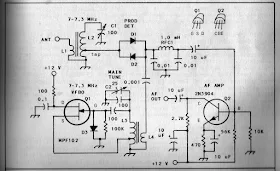
 I was looking through W1FB's Design Notebook the other day and I came across the above schematic for a direct conversion receiver (page 111). Note the Polyakov detector. One strange thing though: Doug was running the oscillator at the operating frequency. I thought the big advantage of the Polyakov design was that you ran the oscillator at half the operating frequency (that's why it is sometimes called a "subharmonic" detector). Any ideas on why Doug did it this way?
Check out "SolderSmoke -- Global Adventures in Wireless Electronics"
http://soldersmoke.com/book.htm
I don't know why Doug did it that way but that circuit would make a great little test receiver for bench work.
ReplyDeleteMake the VFO band-switching (or use a DDS), a MBT for the front-end selectivity, add some audio bandpass filtering and a speaker amplifier, voila, you'd have a "Vlad The Inhaler"!
73.......Steve Smith WB6TNL
Hello Bill,
ReplyDeleteThanks for the question.
The question ”why?” Is always the most difficult question. I first answered another question. Are L2 and C1 really tuned to 7 MHz? For 7 MHz C1 must be adjusted to 54 pF. For 3.5 MHz C1 should be 216 pF. Further C2 must be adjusted to 7 pF to tune the oscillator to 7 MHz. (C2+100pF=107pF)
So L2 and C1 tune for 7MHz and also the oscillator is tuned to 7 MHz.
In this chapter Doug wrote about DC receivers, in which the oscillator runs on the receive frequency.
So I think that Doug choose the most simple mixer.
Both in terms of number of parts and to avoid a more complex bifilair transformer or extra potentiometer for balance. It's not the best mixer but.... As Doug wrote: This Polyakov mixer does not match the performance of a balanced mixer. Page 112.
I used such a simple balanced mixer in my HDC14 Transceiver, which is doing great, with just 1 potentiometer more. Please look at the handwritten schematic on my website.
http://a29.veron.nl/pa1b-02.htm#rx
So I think, Doug kept it simple.
73, Bert PA1B
The circuit above by Doug W1FB has a mistake
ReplyDeleteThe first Cap(0.1uf) in the audio LPF Pi filter will by pass most of the VFO signal ! so better not have it in circuit .