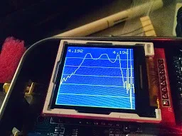
DuWayne (KV4QB) has done something very cool here. He's taken an Arduino Nano, a cheap AD9850 DDS board, a small screen, and a couple of log detectors, and he has built IN AN ALTOIDS TIN a scalar network analyzer that lets you see the bandpass of a filter. (We posted an earlier version of this here: http://soldersmoke.blogspot.com/2015/01/duwaynes-ad9850-arduino-tft-swr-scanner.html ) Wow. I've been doing this by hand, changing the input freq at 100Hz increments, measuring the output, putting the results into a spread sheet, converting to log (db), creating a graph... DuWayne makes it a lot easier. DuWayne is being encouraged to write up the results, possibly for QRP Quarterly.
Hi Guys
Started playing around with the SWR scanner that I had been working on. Waned to see how hard it would be to make a very simple scalar network analyzer out of what I had. Really wanted something small to use for checking bandpass other filters. Hoped to get about 30 db. of range ,which should be enough for most filters. I have a couple of 8307 log detectors, but was afraid that it would be a pain getting it working and shielded in an Altoids tin along with the rest of the circuitry. Went with something even easier than the resistive SWR bridge I already had. Replaced the bridge with two basic diode RF probes, and changed the amplifiers so I could adjust the gain. I use one to measure the direct output of the 9850 DDS module, and the other for the output of the device under test. Kept the same control function as in the SWR scanner. A short push on the encoder button starts a sweep of the selected band. Holding it down for over a second cycles through the bands. Once a scan is done you can use the encoder to scroll through the sweep. I display the frequency and iDUT value in db relative to the output of the DDS module. The USB connector is available and different start and stop frequencies can be entered if needed when working with IF stages.
Well it worked much better than I had expected. After a simple adjustment of the amp gains with the output looped directly to the input, I was getting nearly 50 db with the loopback removed. Just using some standard value resistors, in a pi attenuator I got a very nice looking sweep that was within a couple db of the 40 db i had built it for. Since I only used standard value resistors, I though this was good enough.
Then I used ELSIE to design a 14mhz lowpass filter, again used standard values for L and C that I had on hand . Really happy with the results I got.
Finally I grabbed 3 crystals out of a bag without checking frequency or other parameters, I threw together a basic crystal filter. Used the USB interface to set the sweep range, I was really really really pleased with the results I was able to obtain.
Attaching some pictures of the progress so far. As you can see that with what I used to build the test fixtures, I am amazed that they even worked at all.
73 DuWayne
Our book: "SolderSmoke -- Global Adventures in Wireless Electronics" http://soldersmoke.com/book.htm Our coffee mugs, T-Shirts, bumper stickers: http://www.cafepress.com/SolderSmoke Our Book Store: http://astore.amazon.com/contracross-20


Beautiful project! I'm impressed with how well it is packaged, and the dedicated display is awesome!
ReplyDeleteAnother project to look into if you are looking for a ready made pcb to implement a scalar network analyzer, check out the poor ham's scalar network analyzer (PHSNA). There is a yahoo group. Chat with the designers also did a great podcast with the guys behind the project. Look for it here:
http://cwtd.org/
73 de KF7RPI
Excellent build. Is there any chance the diagram and firmware will be available online any time soon? I am in the process of building a BITX and I miss an HF spectrum analyzer to test its filters...
ReplyDelete72 de IK1ZYW
I have started a Blog KV4QB.blogspot.com Information for building it is on there. I have the schematic, eagle cad layout, and sketch linked from there
ReplyDeleteDuWayne