Thursday, March 31, 2016

From Wayne and Garth in San Diego: EMRFD Joy of Oscillation Part 2


Oh great and mighty masters of the SolderSmoke:

We've continued on with this project and it has been a lot of fun.
Sure, there's
THE JOY OF OSCILLATION
but we've progressed to
THE JOY OF MODULATION (added a keyed buffer)
THE JOY OF AMPLIFICATION (added driver and PA, not threatening QRO, yet)


THE JOY OF RADIATION (perhaps my favorite)
THE JOY OF RECEPTION (picked up by RBN, yeah!)
last on the list is to experience
THE JOY OF COMMUNICATION

for that, we'll try out a number of different receivers.  Cheap SW
portableSoftrock Lite.  websdr.org.

Does one try to count all the joys?  :-)

Here's a few snaps:

0.jpg - RBN evidence
1.jpg - lashup on the lid of a tupperware container
This worked great for throwing the work in progress in a backback for
our build session meetups.
2.jpg - Fig 1.34 less output LPF.
3.jpg - The missing LPF.  THE JOY OF FILTRATION  (OK, that's taking it too far.)


4.jpg - Fig 1.35 amp with BD139 transistor.
5.jpg - "breadboard" and a front panel to hold the T/R switch.  Key
and cheap SW portable for RX.  Waiting for DX contest to end, so I
have a chance.  :-)

6.jpg - simple breadboard chassis

Our fun has certainly been cheap.  The parts cost, including PCB and 1
BNC jack, was about $13 in low quantity from Mouser (and Diz) for all
but the amp.  The amp portion was $4 in low quantity from Mouser (and
Diz), and most of that was the expensive heatsink.  The "chassis" was
just a piece of cheap 3/4" hardwood and lexan from home depot.  I
drilled and tapped the holes in the wood for the #4 screws.  (Seems to
hold quite nicely.  I thought I might have to harden the threads with
CA adhesive as is done sometimes with balsa.)

If there are any of those air variable caps left that you are meting
out to the worthy, well, like Wayne and Garth, "we are not worthy."
If you do have between 1 and 4 and find it in your heart, we'd be very
grateful.

Best regards,

Drew
kb9fko
San Diego

Tuesday, March 29, 2016

Renewed Hope for Divide by 2 I and Q

An anonymous reader posted this interesting message in the comments section yesterday.  Very interesting.   A potentially important tip that may help in the quest for 90 degree phase shift with divide by 2 Flip Flop circuits.  What do you guys think?   And who is that masked man?

I wanted to make a comment regarding your Frankenstein R2 Clock divider, but did not come around to do it until now and fear if I were to put it below the appropriate post, it would be so many pages away nobody sees it. Please forgive me for posting this here if my assumption is wrong. I had a play with two edge-triggered JK - Flip Flops (74HC109 & HC107) and tied the J and K to the appropriate rails to use them as T- Flip Flops. Because of one being positive, the other one being negative edge triggered, this behaves as a divide by 2 IQ clock generator. The HC107 has an inverting clock input, so as with the other design, some kind of inverter is involved. And as Bill has reported, I initially measured the Phase shift on the scope to be off. But while playing around, I realized this was a function of the signal level. I could tune the phase shift by adjusting the signal level of the driving clock! When the clock and power supply levels were almost equal, the phase shift was very close to 90° and pretty stable with frequency (tested with 1-10Mhz). Later I thought about it some more and suspect it might have to do with the exact time the inverter "flips" on different signal levels in relation to supply voltage level. Aside from the exact cause, I believe one could vary the supply voltage of the gates with the same effect on the phase shift as with varying the signal level. I hope my observation helps to somewhat make the advantages of divide by 2 IQ clock generators more accessible.  

Sunday, March 27, 2016

Grayson Evans TA2ZGE on "QSO Today"

Picture


Eric 4Z1UG has a really great interview with Grayson Evans TA2ZGE.  I'm writing this as I listen.

My reactions:

I sympathized completely with his reaction to EE professors who insisted that current flows from positive to negative.  Indeed.  Let's turn those arrows in the diode and transistor symbols around!

I too stripped down a Heathkit VFO and rebuilt it from scratch.

I share Grayson's aversion to metal work.  Viva Manhattan!  

Here is the interview:


Saturday, March 26, 2016

Switching to a Resistive Splitter on the Frankenstein R2


I did a little work on the Frankenstein R2 phasing receiver.  I noticed that I had a lot more noise and hum on 30 meters and above than I did on 40 and below.  I don't think it was common mode hum -- switching to a battery supply didn't help much.  But when I took a look at what happened to RF signals between the antenna connector and the input to the DC receiver mixers,  I noticed that the signal level seemed to vary quite a bit with frequency. 

There were only two circuits in there:  a 1.7 MHz high pass filter (to knock down AM broadcast interference) followed by a simple bifilar toroidal transformer signal splitter.   My guess is that the 1.7 MHz high pass filter's response was being messed up by the bifilar toroid transformer that I was using as a signal splitter. There might have been some unplanned-for resonances between them. This might have had the effect of knocking down the higher freq signals, making any noise in the receiver (probably from the digital VFO) more apparent.  Also, I noticed that I had this toroid too close to the digital VFO box and to the DC power plug for the Arduino/Si5351 combo -- that might have been sending some noise into the DC receiver input. 

To make a long story short, I took out the toroidal signal splitter and went with a resistive splitter like the one above.  This seems to have helped quite a bit.   I know it adds some additional loss -- about 3 db over the toroidal transformer, right? 

Another possibility:  While rummaging around I found a little 3-terminal TV signal splitter.  It is marked "5-900 MHz" but I'm guessing it would be fine down to 1.8 MHz.  Any thoughts on trying that?  

Friday, March 25, 2016

KK7B's Thoughts on Notebooks, Experiments, and Building

From the r2pro yahoo mailing list:

Hi All,

Some interesting posts lately, with notes or links on "to build or not to build," new H-Mode mixers for HF, and front-end filter intermod.  A recurring thought is that I do lots of projects and each of my projects is a separate design, starting with a bunch of sketches.  I didn't invent this approach--think of DaVinci, for example.  I don't count my sketches, but probably make ten or twenty for every one that progresses to a design of something that would actually work, and maybe only one in ten of those makes it to prototype hardware.  I do a lot of sketches--hundreds for every working radio, and maybe finish a dozen working radios for every one that I write up, either as a good or bad example.

But my sketches all seem to have something in common--they are sketched to do one particular thing well.  They tend to be for one band, one mode, and are designed with particular power supply limitations and the antenna I'm going to use known ahead of time.  They often include at least one but no more than two experiments--something new and risky enough that it might not work.  More than two experiments almost always end up interacting in some unpredicted and dysfunctional way, so I try to limit risky new brilliant ideas to no more than one or two per project.  The key is to do lots of projects, and lots and lots of sketches.

I don't normally operate in brutally strong signal environments, so my dynamic range/IIP requirement is already satisfied with techniques that have been standard since all the excellent work by Wes Hayward, Ulrich Rohde et al. in the 1970s and 80s.  The problem has been solved, like the appropriate number of wheels on a bicycle.  Sure, there are extreme enthusiasts who limit themselves to one wheel and play the bagpipes while riding...  My risky new front-end sketches are often aimed at meeting those acceptable prior benchmarks in some clever and different way, rather than adding a few dB on top of already good dynamic range.  ...Yes, that works well, but I think I'll try doing it this way instead...

Similarly, my input filters aren't the limitation on my intermod performance.  PIM is a big deal in some contexts, and the latest research is fascinating.  Do a google search on Passive Intermodulation PIM to get started on some interesting reading on that topic.

Regarding the question "to build or not to build," I believe that comes down to something very basic: are you a builder?  If yes, then you have no choice.  I can look around my radio room and see a hundred different radios that I've designed and built, and a few more in progress.  If you do the math in my first paragraph above, that's around ten thousand sketches.  My lab notebooks have 200 pages, and I've filled up 140 notebooks since 1975, so that figure is reasonable.  It's just something I do, like some guys go fishing.  Sketches don't take long.  I can do two or three on a half-hour train ride on the way to work.  A complete design to where I start cutting metal and gathering parts might be a few hours a day for a week.  Then another month, maybe a few hours at a time on weekends to finish up a nice project.  There have been more than 2000 weekends since 1975, so even 100 completed radios has left most of my time for other things.

I am very close to folks who are the same way writing code.  They've been filling notebooks with it since grade school, and doing Software Defined Radio since long before they ever encountered the abbreviation "SDR."

If your personal sketches are full of code or CMOS logic, I expect your radios to look and work differently from mine.  If you operate 6m weak signal modes a half mile from a hilltop kilowatt contest station, you have a fascinating set of dynamic range problems to solve.  Years ago, my 11 year old daughter and her best friend thought the absolute best radio ever was the morse code transmitter that Wes Hayward and Bob Culter worked across town using a couple pieces of metal stuck in a lemon for power.  Neither Wes nor Bob would embrace the limitations of that rig for all their amateur radio contacts, but at the time it was a really cool project.

These are just some rambling, Saturday night thoughts, but if you read between the lines you can maybe understand a bit more of why I tend to do things some interesting way that might not apply to your particular application.  One time I accidentally left one of my notebooks at a close friend's house, and he took the liberty of making copies of a bunch of the pages.  I'm not sure it did him any good, but he sure found it entertaining.  There is great freedom in sketching things that have a small probability of actually having to work well in practice.

Enjoy the experiments, and if you have self-identified as a builder, as have many of the denizens of this site, then enjoy making sketches, developing designs, and taking risks that either pay off or end up as learning experiences.

Best Regards,

Rick

Thursday, March 24, 2016

Be afraid! Be VERY afraid! Digital Audio on 20 Meters (video)


Here is a very interesting comparison between digital audio, and plain old SSB audio (from a Collins rig!).

I don't know.  I may be prejudiced here, but that digi audio just doesn't sound too good to me.  And I ask myself: "How could it?"  They are restricting the transmit bandwidth to 1.2 kHz.  Can the error correcting elements of the software help them get around the bandwidth limits of Shannon's communications theory?  

The digi audio sounds quite robotic to me. Even Siri sounds better.  Is this because -- as the receiving station noted -- they were only getting "80 percent decode"?   Would the digi audio have sounded better if signal strength had been better? 

Again, I don't know.  But remember. I am a Ludite (with a single d -- the ORIGINAL spelling!).

Tuesday, March 22, 2016

W6JL's Amazing Phasing Station


Eric 4Z1UG interviewed Don Huff W6JL a few months back.   I really like Don's approach to homebrewing.   I recently came across his QRZ.com page -- I was lured in by the phasing receiver with the Tayloe detector.  And of course I like the modules spread out in the desk.  FB Don.  

Here are the details on Don's rig:


Here is Eric's interview on QSO Today:


Monday, March 21, 2016

Could Grayson's Arduino Thermatron Shield Protect Us From Digi Domination?

Something old, something new, eh Grayson?   The author of "Hollow State Design" is engaged in an (I suppose) admirable effort to bridge the gap between our beloved Thermatrons and those new-fangled Arduinos.  Here Grayson tries to explain and justify his flirtation with the dark side:

I want to do some experimenting with Thermatrons and Arduino.  Sound weird?  Maybe not.
I really like playing around with the Arduino even though it violates my ban on digital technology in my shop. (My excuse is I am trying to use it teach my son something he can use to get a job someday.)

Sure Grayson.  That's what they all say.  "I was doing it for the kid..." 

Kidding aside, that tube shield looks pretty cool.  And I like the MeTubes base for the Thermatron.


Sunday, March 20, 2016

Winterfest Hamfest with Armand WA1UQO

 I had a great time at the Vienna Wireless Society's  Winterfest Hamfest.  As I have done for several years now, I joined forces with Armand, WA1UQO. A prediction of cold rain caused many of the tailgaters to stay home, but there was still a lot of good stuff to be found at the 'fest.  I came home with a large stock of potentiometers, a 130 foot doublet with open wire line, TWO copies of SSDRA (one given to me by Armand) and various other bits and bobs (including some Cadmium Sulphide light sensitive resistors....)   I successfully resisted the siren calls of several old Hallicrafters receivers.  After the 'fest Armand came with me for a visit to SolderSmoke HQ.   Armand always brings along some part to be used to help members of the International Brotherhood in their radio endeavors.  This year, that included several 80 meter crystals suitable for Michigan Mighty Mites and the ColorBurst Liberation Army.  Thanks Armand!  And thanks to the Vienna Wireless Society.  

Saturday, March 19, 2016

Great Video on Mixers


You know that you are sinking deep into The Knack when you watch a video like this one and find yourself thinking: "FANTASTIC!  WOW!  Now I know why square waves are better!" I really liked this one.  In the beginning I was kind of concerned about his refusal to explain how non-linear, non-switching mixers work.  He actually used the dismissive non-explanation that I've always found so disappointing:  "Blah, blah, blah... it's in the trig."   And he actually said, "Blah, blah, blah." But he more than made up for it when he got into the switching mixers.   Note that his drawing (at the start) of "Mixing by Switching"  attempts to show the waveform that results from an LO "chopping up" an incoming RF signal.  I always find that picture worth a thousand trig equations.

I also really liked his explanation of the benefits of rapid rise time in switching mixers, and how slow switching causes the diodes to spend some time in the non-linear part of their curves, giving rise (!) to IMD products (I'm paraphrasing).  You can really see why they say it is better to drive diode rings with square waves.  So stop trying to put low pass filters between your LO and the diode ring.  Square waves are your friends here. 

Mr. Marki seems to be one very cool EE.   And I'd like to hear more about his dad.  Here is some more about the Marki engineers:

http://mwexpert.typepad.com/markimicrowave/

GREAT Video on Mixers


You know that you are sinking deep into The Knack when you watch a video like this one and find yourself thinking: "FANTASTIC!  WOW!  Now I know why square waves are better!"

I really liked this one.  In the beginning I was kind of concerned about his refusal to explain how non-linear, non-switching mixers work.  He actually used the dismissive non-explanation that I've always found so disappointing:  "Blah, blah, blah... it's in the trig."   And he actually said, "Blah, blah, blah." But he more than made up for it when he got into the switching mixers.   Note that his drawing (at the start) of "Mixing by Switching"  attempts to show the waveform that results from an LO "chopping up" an incoming RF signal.  I always find that picture worth a thousand trig equations.

I also really liked his explanation of the benefits of rapid rise time in switching mixers, and how slow switching causes the diodes to spend some time in the non-linear part of their curves, giving rise (!) to IMD products (I'm paraphrasing).  You can really see why they say it is better to drive diode rings with square waves.  So stop trying to put low pass filters between your LO and the diode ring.  Square waves are your friends here. 

Mr. Marki seems to be one very cool EE.   And I'd like to hear more about his dad.  Here is some more about the Marki engineers:

http://mwexpert.typepad.com/markimicrowave/


Wednesday, March 16, 2016

VA2NM's Michigan Mighty Mite (with Tuna Tin LPF!) (video)


Tuesday, March 15, 2016

A Great Knack Story: Peter Parker Interviewed on "QSO TODAY" by 4Z1UG


I really liked Eric's interview with the Peter "The Wizard of Melbourne Beach" Parker aka VK3YE. What a great Knack story!  There he was, trolling the garbage dumps of Western Australia, looking for discarded electronics.  Using the LO of one broadcast receiver to demodulate SSB signals coming in on another... Great stuff!  Check it out:

http://www.qsotoday.com/podcasts/vk3ye

Monday, March 14, 2016

HEAVY METAL! How to Handle HEAVY Boatanchors -- And Which is Heavier: R390 or DX-100?


Grayson: 

I was on 40 AM today and I mentioned to the guys your thoughts about the possible need for a block and tackle and a metal beam in your shack roof to help you deal with your R-390A.  They sympathized completely.  One fellow claimed he knows hams who are working out with weights just so they can handle their boatanchors.  Another guy said he is thinking of building a small crane, perhaps powered by his chain saw (yikes!).  A third fellow said he actually bought a thing called a "lifting table" from Harbor Freight.  

This got me to thinking:  How much do those R-390s really weigh? 

A MERE 85 pounds!  That's it?  Holy cow, the DX-100 has a listed shipping weight of 120 pounds!

73  Bill  


Bill:

Nice thing about a “regular” boat anchor (DX100, HT37, SX101, etc.) is that you can put it on its side and get fairly easy access to both sides, and all the components at once.  The problem with the R390 (and a lot of Collins military gear) is Collins worked hard to cram so much in a “small” space that you have to take whole sections apart to get at anything.  So you have to “flip” the chassis over, side, over, on its back, etc.  UGH.  To get at the RF front end components, you gotta take the front panel off before you can remove the RF chassis.  UGH

I know about the lifting table from harbor freight.  A really nice shack accessory.  Puts the rig at a better height to work on.  With a “lazy susan” thing on top, a nice arrangement!   Maybe next Christmas.

73, TA2ZGE


Grayson
TA2ZGE - Ankara, Turkey
KJ7UM
Follow the Hollow-State Design Blog


Sunday, March 13, 2016

Another Lightwave Communication Knack Story from the UK


Hi Bill,

I've been following your podcast since you started and enjoy every episode. I've been licensed here in Scotland since 1970 as GM8EUG.

I thought you/others might be interested in how I got into radio/electronics and how I feel I may have the 'Knack'. 

The above reference reminded me of some experiments I carried out in 1967 as a schoolboy. There were no ready sources of parts locally for me.. I lived  in a rural area so the nearest electronics parts shop was 50 miles away so it was all done by letter and mail order.

My first audio link was driven by a tube broadcast receiver with a 3 volt torch bulb connected instead of the loudspeaker. (I hadn't heard of impedance matching!)  This flickered nicely on speech/music peaks. The bulb was positioned at the focal point of a parabolic car headlamp reflector from a scrap car.  I now had a beam of light with audio on it.
Next step was the receive side...I didnt have access to a photo cell but had a Cadmium Sulphide photo resistor. Connecting a pair of low impedance headphone in series with this cell and a 1.5 volt battery gave me recognisable audio when the cell was in the beam...no amplifier needed!

Next step was greater range...this was achieved with a 6 inch shaving mirror to focus the beam onto the photo resistor. This gave me the length of the street (100 yards when it was dark outside )with the flickering beam shone out of my schoolboy bedroom window resulting in puzzled  looks from passers by.

Next problem was the frequency response.. all bass and no treble. Some research indicated that the photo resistor had a slow response so that was part of the problem but I had a hunch... How fast does a filament bulb react to audio? Biasing the bulb with a 1.5 volt cell so that it glowed  dimly with no audio improved the audio response greatly.

So what got me into radio...my father was a Chief Radio Officer in the Merchant Navy during WWII and my schoolboy bedtime reading (the only technical stuff I could find ) was his textbook ...the 1939 edition of the Admiralty Handbook of Wireless Telegraphy. Capacitors  were called condensers and they were measured in 'jars'!

That was the start of a career. I've now moved through testing international telephone exchanges, installing 2 way radio for the whole of Scotland for British Rail (paid for my hobby!) and finally 32 years in IBM writing manufacturing test software from the original IBM PC to Thinkpads.
Now retired I am active on WSPR and am writing Android apps to keep my brain in gear.

I just can't leave this stuff alone!

Hope this of interest/amusement.

73s

Neil Roberson GM8EUG


Saturday, March 12, 2016

EMRFD Joy of Oscillation (Part 1)


Guys:

I have been catching up on the last few SolderSmoke podcasts after
that little QSO Today diversion.  I wonder how many others did the
same thing?  I have really enjoyed these recent 'casts.  Lots of
fantastic HB content.  Funniest moment was when Bill described his
post-project workshop as looking like the aftermath from an electronic
barfight.

I took a new ham up on a SOTA activation last year.  Then about a
month ago, he said that he wanted to do HF HB.  He said he had been
googling and found so much that he didn't know where to start.  I told
him that I'd be interesting in doing a beginner HF HB project with
him.

I could have pointed him to LBS, et al.  I could have pointed him to
the Michigan Mighty Mite.  I did neither.  I pointed him to:
http://web.cecs.pdx.edu/~campbell/EMRFD1dot34.pdf  Note the name of
the document.  I pointed him also to:
http://www.arrl.org/files/file/Product%20Notes/chapter_1.pdf 
(Did you guys know that chapter was online and free?)  We scaled to 20m and
kitted parts for this.  And parts for a 4th transistor PA for serious
QRO.  :-)

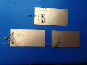
Two others joined us building for 40m.  Check out the attached photos
of the first 3.  The joy of oscillation was experienced by all.

After testing each oscillator, and borrowing from an article KK7B ran
in CQ VHF, I told each that he had to ID every 10 minutes.  Even
though nobody was going to hear these signals a few hundred yards
away.  (But it sounds loud on a shortwave portable a few inches away!)
 I even wrote out the dots and dashes for a couple of them.

Next stop:  to have everyone find a curbside TV discard, rip out some
parts, and get on 5 meters!  Haven't we gotten it back now, after the
transition to digital TV?   :-)

OK, maybe the next stop is to add some gain stages and experience the
joy of communication.  The joy of QSO-ification?  The joy of
EM-radiation?  :-)

Best regards,

Drew
kb9fko


2 Attachments

Wednesday, March 9, 2016

Elser-Mathes Cup Opportunity!


I'm sure he'll be on the air.  With a homebrew rig.

Stay thirsty my friends!

A Knack Victim's Midlife Crisis


Thanks to Steve WA0PWK for sending us this Jim Williams cartoon.  

Been there, done that. It doesn't mean you are a bad person.

Tuesday, March 8, 2016

German Mighty Mite works Venice on 40 (video)


In spite of being a bit off frequency, sTef,  DL1FDF (aka VY1QRP) has been inducted into the Color Burst Liberation Army.  Congratulations sTef!  Normally we would requite operation on 3.579 MHz, but sTef has been granted special dispensation because 1) he doesn't have a 3.579 MHz rock, 2) our stock of this crystal has been depleted, and 3) he actually made a contact with this rig, working II3ICZ in Venice.  FB sTef.  If anyone has a color burst crystal for sTef, please let us know.    

sTef writes:

I would like to say „Thanks" to both of you for your ongoing inspirations in soldering and homebrewing.  After 15 years out of ham radio it were you two guys who got me back into the world of -> SOLDERSMOKE. Thanks for that.And belive me been away for 15 years and now getting back into it feels a sometimes a little bit too "digital“ …. ARDUINO or NOT TO ARDUINO ? This is the question….
Anyway…
So what could be more sophisticating than having a MMM ready on the work bench and answering a CQ call on 40m with that thing and be heard. 
Yes, the first QSO today with my MMM was for you both.
I worked the Italian Radio Station II3ICZ. I was 559 into Venice with 0.5 watts from the MMM into my full-size triple leg for 40m.


Monday, March 7, 2016

Adafruit Profiled in "The New Yorker"

Limor Fried describes the Circuit Playground as “the Happy Meal of electronics—everything you could possibly want and a toy, too.” Her goal was to squeeze all of her company’s most popular pieces of hardware, including L.E.D.s, a range of sensors, and “a really annoying beeper,” onto a single affordable device.

Congratulations to Limor Fried.  Her company got a very nice write up in "The New Yorker."

http://www.newyorker.com/tech/elements/limor-frieds-artful-electronics

Sunday, March 6, 2016

"My Favorite Programming Language is Solder" -- Boldport Kits

Look closely at the inscription on that USB stick.   Obviously I sympathize.   The folks at Boldport have some very interesting ideas and projects.   And they operate from a very cool location, just south of the river Thames, not far from my old home in London. 

Here is their main site: http://www.boldport.com/blog/2016/2/21/boldport-club-project-1

Here is where you can subscribe to receive a monthly project (with parts!) from them:
https://boldport.cratejoy.com/

As for the solder quote from Bob Pease, this was discussed before on this blog, back in 2011.  We were talking about an intereview that had been done with Alan Wolke W2AEW:

I also liked Alan's response to the question about his favorite software tool: "Gee, solder is soft, can we consider that software? I use a lot of that!" This is very reminiscent of a quote from the legendary Bob Pease (colleague of Jim Williams): "My favorite programming language is solder." (That quote was sent to me by Steve WA0PWK. Thanks Steve.)

Saturday, March 5, 2016

AA1TJ -- On the Air with a Tuning Fork Transmitter using the 2,212th Harmonic and Olive Oil Cooling

The saturable magnetic frequency septupler. The tiny computer memory core is submerged in olive oil (Italian...naturalmente).


Not a very good picture, but here's the 1600Hz tuning-fork, fork oscillator, SRD pulse generator, PLL S/H phase-detector (diode gate), differential amplifier D.C. amplifier, and part of the 500kHz VCO.


The Wizard (AA1TJ) reports from the Hobbit Hole:

I was pleased to have made the first contact with my tuning-fork transmitter this evening. My contact, N1QLL, runs a pretty B&B on the Maine seacoast, midway between Bar Harbor and Cutler. Jerry was operating a solar-powered QRP station.  I found a follow-up email from him when I came up to the house for dinner. He's asking for a better explanation of my set-up. I can't wait to tell him about the passive frequency septupler made from an East German computer memory core, heat-sinked in a thimble of olive oil. 

My signal was also logged by a number of automated "Reverse Beacon Network" receivers (image attached) located in Ohio, North and South Carolina, Virginia and Pennsylvania...not bad for 90mW on 80m. Please note that my operating frequencies, 3,528.0 and 3,539.2kHz, are the 2,205 and 2,212th harmonics, respectively, of my 1,600Hz tuning-fork frequency reference.
FYI: the third attached image illustrates the block-diagram and tuning-fork reference oscillator circuitry for three common-wavelength AM broadcast transmitters operating in Berlin, Stettin and Magdeburg, Germany from 1928 through the mid 30's. A central 2,000Hz tuning-fork generated reference carrier was transmitted by landline to transmitters in the aforementioned cities whereupon the 529th harmonic was generated, amplified and broadcast at 1,058kHz. The equipment was designed by the Berlin-based firm, C. Lorenz A.G.. The fourth image details Lorenz' technique of frequency multiplication via saturable magnetic iron-core inductors. My septupler operates in an identical fashion.
A very pleasant day...


Mike points out that this is a work in progress.  He hopes to cross the pond (the Atlantic!) soon. Here is a update from Mike:

A nasty cold has delayed work on the 20 meter implementation, although some of the time I've spent crashed on the sofa was put to use redesigning the loop filter network. I think yesterday might have been my "hump" day so I'm looking forward to getting in some quality bench-time over the weekend. 

By the way, my PLL-based transmitter frequency stabilizing circuit has much in common with a garden-variety frequency-synthesizer. Obviously, the tuning-fork frequency reference is the main point of departure. My sampling phase detector, for example, was old hat by the mid-1960's. Nevertheless, this has been a fun project.

Friday, March 4, 2016

That Time We Were Re-Transmitted on 487 THz On a Red Light over Salt Lake City....


Some of you may remember this from back in 2012:

http://soldersmoke.blogspot.com/2012/09/soldersmoke-in-red-light-zone.html

Fast forward to November of last year. By this time I'd forgotten about the Utah light beams.  Ron Jones, K7RJ, was kind enough to send me a wonder-filled bag of electronic parts.   I have been slowly sorting them.  All kinds of great stuff is in there, but I noticed a lot of stuff that you don't normally find in ham shacks -- lots of optical stuff, lots of LEDs and photo transistors, little transistors with lenses on the top.  Cool stuff all, but not the kind of parts you'd use for a 40 meter CW rig.  What the heck was Ron building?  I wrote and asked.  Here is his reply. 


I’m like you, Bill, I’m a jack of all trades and master of none. I dabble in this and that. I always have a hand full of half finished projects on the bench.

 The optical stuff probably fell on the floor when Clint (KA7OEI) and I were experimenting with “through the air light communication” a few years back. Clint in the real guru in that particular project. We made optical contacts over what we think is a world record – 173 miles! That meant packing in optical gear to the top of remote Utah mountains, but what a great time we had!  We used a high power LED – NOT a laser. Lasers really suck for super long range communications. They are great for wide band across a parking lot, but not for voice communication over tens of miles (in our cast 173 miles) over the  air. We did over 100 miles with a laser pointer – can you believe that? A $3.00 laser that you torture your dog with… 100 miles!  But, that is a different topic. If you do say anything about the optical stuff, be sure to mention Clint, he really engineered the optical communication project.

By far, most important thing that we did with optical communication was on one of our short tests (only about 50 miles) when we broadcast one of the Solder Smoke episodes for anyone who cared to “look in” on our red beacon.  I think Clint sent you a picture from his side of the path a few years ago.
 
If there are any parts in that pile of junk that you are particularly interested in, I may be able to find more data and/or circuit ideas I had. But, honestly, a lot of that is stuff that is as strange and wonderful to me as it is to you. Fun as heck to look at, but needs to be put in the “YAFP” pile (Yet another .. project). 
 
Thanks for doing the podcast. It is always an inspiration for me to keep my soldering hot. 
 
73
Ron K7RJ 

Very cool.  So Ron had been at the other end of Clint's Red Light beam, the light beam that was carrying a SolderSmoke podcast across Salt Lake City.   And it appears that some of the parts involved in that amazing project have ended up in my junk box.  The Radio Gods like this sort of thing and may have been at work here.   Thanks Ron. 

Thursday, March 3, 2016

DD4WH's Fantastic Teensy SDR Receiver (Videos)


This is almost enough to make me abandon my analog, discrete component, HDR fundamentalism.  Check out that display.   And that StereoAM mode in which the upper and lower sidebands go to the left and right headphones "useful for CW"... Wow, that's seems like a step beyond binaural.

Don't miss Parts 2-4 --They are all on YouTube and will appear in the right hand column when you are watching Frank's videos.  But I couldn't resist embedding the video that shows the hardware.  Note:  the oscillator is an Si5351!   Yea!  And the LP filter board comes from Hans Summers.


Beautiful work Franz!   Thanks for making the videos.  73  Bill

Wednesday, March 2, 2016

From Paul Darlington M0XPD: A Book!


Our friend Paul Darlington M0XPD is a member in good standing of the International Brotherhood of Electronic Wizards. His AD9850 Arduino shield propelled me into the world of I and Q. His "Shack Nasties" blog is a valuable resource for all of us. And now he has written a book.  Paul was kind enough to let me read it before it was published -- I enjoyed it very much.  It is the story of a very personal journey. At one level it is about Paul's trip to the Dayton Hamvention.  But the trip goes much further than Dayton, both geographically and personally.  I especially enjoyed Paul's observations on the United States -- our British cousins often see things we ourselves overlook.   I'm really pleased that George Dobbs wrote the foreword -- he is the ideal person to do this for Paul's very philosophical book.

We give "Getting There" our highest review:  the coveted FIVE SOLDERING IRONS. And we are nominating Paul for a Brass Figlagee with Bronze Oak Leaf Palm.  

Read Paul's description of the book here:

Buy the book here:

Congratulations Paul!