I hope many of you decide to build this little receiver. With it, you can break into the ranks of those intrepid ham homebrewers who have actually built a receiver. Today I'll begin a series of blog posts on how you might do this. Of course, there are many ways of proceeding. I will describe my method.
FIRST: ALWAYS look at this receiver as a collection of stages. Understand what each stage does and how they all work together. Build it stage-by-stage. Proceed to the next stage only after you confirm that the stage you just built actually works.
I see this receiver as having four stages:
1. Front end (RF gain control, input filter, first RF amplifier).
2. Mixer
3. Ceramic resonator variable frequency oscillator (and buffer)
4. Audio amplifier (consisting of four transistors and associated parts).
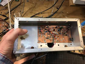
In the picture above you can see the four stages. On the left side of the copper-clad board you can see the Front end: the input filter and the RF amplifier (transistor near the top). Moving toward the center you can see the mixer stage (around the circular 1k trimmer potentiometer). Below the mixer (near the big round hole in the Bud Chassis) is the Variable Ceramic Oscillator stage and its buffer amplifier. The right 1/3 of the board is taken up by the audio amplifiers. Note the use of Manhattan pads throughout. Click on the picture for a closer look.
What you will need: In most cases, you shouldn't buy individual parts for this receiver. I won't be providing a BOM. Here is what I think you should do. If you do not already have a good stock of electronic parts, start developing one. Buy assortments of parts, or at least several of each part that you will need. I use e-bay, amazon, mouser, digikey. The parts are out there.
-- Get an assortment of resistors. 1/4 watt resistors will do.
-- Get a bunch of .1uF capacitors. You will use a lot of these as bypass caps.
-- Get a bunch of 2N3904 and 2N3906 transistors.
-- Get a bunch of 2N2222 transistors
-- Get a bunch of MPF102 and/or 2n2819 FET transistors.
-- Get an assortment of small electrolytic capacitors.
-- Get some Zener diodes in the 6-8 volt range.
You will need some trimmer caps (8-80pf work fine). Some 1K trimmer pots. and some other stuff.
Get some copper clad board. Pete suggest this, or something like it.
https://www.ebay.com/itm/18-pcs-4-x-6-CEM-1-060-2-oz-Single-Sided-Copper-Clad-Laminate-Board-PCB/311756276147?ssPageName=STRK%3AMEBIDX%3AIT&_trksid=p2057872.m2749.l2649
Try to avoid the cheap fiber glass boards. I prefer single-sided, but double sided is OK too.
You will need to cut the board. Get some tin shears. Mine look like big strong scissors. Use them to cut your boards to size AND to cut the little isolation pads for Manhattan construction.
Crazy glue. I kind of like Gorilla Glue liquid (not gel).
Small wattage soldering iron. 35 W or so. Get a small fan to keep the smoke and glue fumes out of your respiratory system.
I used a piece of scrap wood to get the variable cap into position.
Here it is with my fancy Archer Dial. I used a bit of copper clad board to finish the front panel
and to support the audio gain control.
Next time I'll write about how you might build the Variable Ceramic Oscillator stage.


looks beautiful Bill.....I'm starting to dig through my junk box for parts!!!!
ReplyDeleteFB!
ReplyDeleteHi Bill,
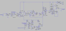
ReplyDeleteYou might include a link to the schematic (or a copy) here, so that people don't have to hunt for it. I think this is a great starting project!
Josh, KB8NYP
Schematic?
ReplyDeleteMaybe Bill wants us to reverse engineer the schematic based on the picture of his Manhattan design :) I think you can find the schematic for this project here: http://soldersmoke.blogspot.com/2017/11/iphone-direct-conversion-receiver-with.html
ReplyDelete