June 21, 2020
Michigan Mighty-Mite: Why So Complicated?
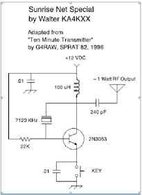
The April 2020 issue of QRP Quarterly magazine featured an article by Bob Rosier K4OCE which included a schematic for a “Ten Minute Transmitter” by G4RAW (SK), which apparently first appeared in SPRAT 82 in 1996.
It is even simpler than the Michigan Mighty Mite, so this transmitter can truly be built on a solderless breadboard in about 15 minutes, because a complex coil is not required.
The only tuning needed was for me to establish the correct value of the output series capacitor.
This rig allowed me to check-in to the Sunrise Net (see details in blue text on my QRZ page) today on my very first attempt, and landed me a 549 signal report from 250 miles away.
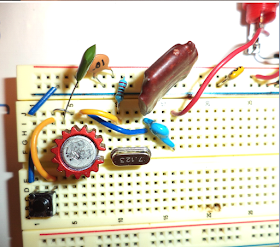
The first photo shows the transmitter connected to a Transmit/Receive Switch mounted in an Altoids box. In the Transmit position the antenna is disconnected from my 1979 Heathkit HR-1680 receiver, which then coincidentally supplies a sidetone at an ideal volume level. That little black pushbutton which can be seen in the second photo serves as my key, and works just fine for a five-minute daily QNI on the Sunrise Net.
Of course, part of the secret is having a crystal exactly on the Net frequency, and I have a few left, free to whomever in the Eastern U.S. is interested in building one of these simple Sunrise Net Special Transmitters and participating in our Net.


And what's the harmonic output look like? A single transistor driven hard, and no tuned circuit on the output.
ReplyDeleteSometimes simplicity is not the route to go.
I was wondering how long it would take for someone to point this out. OK, as with the MMM, you really should add a low pass filter.
ReplyDeleteI just tried the circuit with some parts on hand and measured 0.7-0.8W in to a 50 ohm load after a low pass filter (7th order Chebyshev). Even with the filter, the next harmonic peak is only down ~25dB. The unfiltered waveform is non-sinusoidal to say the least.
ReplyDeleteBy the way, one should make sure to heatsink the transistor, as did the original poster, or else the magic smoke may be released.
DeleteActually I transmitted through a double-tuned antenna tuner connected to an End Fed antenna, which I probably should have mentioned even in a short article. I did not measure the transmitted harmonics, but considering the poor propagation these days and the low power level I do not suspect that I interfered with anyone. Certainly I will work to refine the design and add appropriate harmonic suppression so even inexperienced Soldersmokers can build it and transmit a clean signal. Thanks for the comments. --Walter KA4KXX
ReplyDeleteA example for a possible ARDF transmitter.
ReplyDeleteI'll have a look at the relevant SPRAT article from 1996.
Frank , EI7KS
...Next project....
ReplyDeleteI'm pulling together the parts for this neat little transmitter.
Delete1. Are there known equivalents for the 2N3053 transistor? Does that transistor need a heat sink?
2. Cap values for the key and from the +12V input. Is that .01nF or .01pF?
3. The 100 uH coil. Can I produce that? I'm looking at the Kits and Parts toroid winding calculator. Leads me to believe that I can't produce this value with a simple toroid, correct? Or maybe I'm reading the calculator wrong.
Dear Jack: I am just now seeing your questions more than a year late, but here are the answers.
Delete1) The red ring in the photo around my 2N3053 is an aluminum heat sink, though if I used this rig more often I would use a bigger one. There are many other transistors that could be used, but you would have less chance of success without experimenting and changing one or more component values.
2) The .01 caps are in microfarads, so equal to 10 nanofarads.
3) I used a manufactured fixed inductor, but you could also use an FT50-43 with 14 turns, or see an online calculator for the possibility of using other ferrite toroids.
Why wind a coil when 100 uH 1W fixed leaded axial inductor is easily available, sir. Just use that! You'll, however, need toroids for band pass filter.
DeleteAwais: Walter did use a manufactured coil in his rig. But Jack asked if it was possible to make one. Walter points out that this can be done using a -43 material toroid. Either way, it would work. 73 Bill
ReplyDelete