Jose CO6EC has been digging up 30 year-old Islander schematics for us. Thanks Jose. This one shows a VFO for the Islander. Note that it runs on 80 meters, but they select the second harmonic at 40 meters. This was a smart move that surely helped with VFO frequency stability.
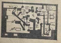
Jose sent this printed circuit board pattern for the VFO. Obviously they were making many of these rigs.
Here is the power supply. Jose reports that the transformer came out of a Soviet Krim 218 TV set. As a kid, I also pulled a transformer out of an old TV -- I did it to build a power supply for a Heath HW-32A.
Here is another version of the Islander. Click on the image for a better view. Jose reports that this version was circulating during the time Islanders were being built. He says this diagram many have been done by Arnie Coro CO2KK (SK), and may have been circulated on the internet.
Here's the first schematic that Jose sent. Again, click on the image for a better view.
I will continue to gather information on the Islander and the Jaguey. If you have any info please send it to me.
Here are some earlier posts on these rigs:
Thanks to Jose CO6EC!


Why not use a high level balanced modulator? Common in the US, and even conversion articles of AM transmitters.
ReplyDeleteBecause its difficult to suppress the carrier at high level. Doing it a low level is way easier.
DeleteInteresting. All European tubes types and the 3rd schematic is stating descriptions in Dutch language. Thanks for sharing!
ReplyDeleteWout, PE1GXH
CO7WT here, built a pair of the Islander back in the time, the most scary part was the power supply.
ReplyDeleteThe 600V is 300ish V from the transformed DOUBLED stright from the transformer and if you look closely on the diagram the doubling capacitor need to be of good quality otherwise it will explode in the spot.
As you can imagine, using scrapped parts means that very often this capacitor explodes, even after a few months of duty, that was a common problem.
We used to use 47uF/800v from Germany that was almost easy to obtain, but exploded like fireworks a given day.
Later I learned that if you put a resistor of about 1k 5W in series and work it for a while like this [no real voltage at the end] it will behave in the future and this trick saved many, a trick that was shared with Coro CO2KK and he found the explanation on the taming/training of the dielectric after storage/inactivity will prevent it from exploding.
I think he made mention this on a DXers Unlimited program...