Somehow, this video fits well with the SolderSmoke theme. It may be that Uri cheerfully acknowledges that the lathe can kill you (the same is true of much of our gear). Or it may be his repeated use of the term "Bob's your uncle" (has he been listening to SolderSmoke?). Whatever the reason, this beautiful video fits here. This is from Uri Tuchman's channel: https://www.youtube.com/@urituchmanpigeon. Uri is in Germany. Thanks Uri!
Sunday, December 29, 2024
Friday, December 27, 2024
Derek N9TD's Magnificent Build of the TJ Direct Conversion Receiver

I think it is magnificent. Derek N9TD fought his EE tendencies and recognized that the perfect can be the enemy of the good. So he went ahead and built this receiver pretty much as we intended it to be built: Four stages: BP filter, PTO, Diode Ring Mixer, Super-simple AF amp.
He went several steps further and added a fixed coil to slow down the tuning and keep it in the 40 meter band. He added an RF gain control. And he went with a steel (vs. brass) screw. But these are all things that I myself have done. (We still advise people to build it the simple way first.) FB Derek.
The challenge is still out there. The gauntlet has been thrown down. Derek's completed project shows us that this project is entirely do-able. Do it!
Derek wrote:
Bill,
Let me introduce myself, I am a recent electrical engineering graduate from Purdue and a long-time listener of the podcast. I want to thank you and Pete for being one of the reasons I chose to pursue my degree in the first place. I'll admit that in the more difficult stretches of getting my degree, I often pulled out the podcast to be reminded of the fun that can be had with radio and electronics.
Until recently I had to hang my head low along with the majority of the other 'appliance operators' out there having never built anything with my two hands that can be used to pull signals out of the ether.
I am no stranger to building projects, PCBs, and melting solder but I usually chose to either stick to the dreaded digital domain or focus on antennas, filters, and other ancillary equipment. The logic being that I like to have a "known good" radio for the shack and that I would focus on other equipment to supplement the radio. I still follow this logic when I want to contest and we all know that antennas are well worth the effort, I've just finally had enough of being an appliance operator and have your podcast to thank for the extra push.
I had been following the original effort of the TJ DCRX with interest from the start and earmarked this project as one I would like to build based on its inherent simplicity and good performance. However, the demands of school and a recent (at the time) abortive attempt to build an AM superhet with an SA602 the year prior made me (I got as far as feeling the joy of oscillation but regretfully petered out after that) put this one the backburner for about two years until December 2024.
By coincidence, I independently decided to start this project just before your show with the HRWB folks and the gauntlet being thrown down, which has spurred many to build this receiver. It has been great to see the extra coverage on the receiver, and the commentary has been very insightful for someone trying to build this for the first time and with as many of the "improvements" as possible.
For better or for worse, I'm the type of guy who wants to understand the "why" behind all the design choices and, from there, try to incorporate as many lessons and improvements as possible to make the "best" version possible. I'm not saying I make the best version of anything, but it's just a quirk of the way I think and justify doing a project. It always has to be "this and some additional improvement;" otherwise, I would decide against doing it.
Rambling aside, I ended up building the DCRX, adding the RF attenuator from N3FJZ's website, and incorporating the lessons you learned after experimenting with improving the tuning on the PTO. I added an external series inductor wound on a dowel rod and used a zinc-coated steel screw as opposed to brass. I found that this gave solid tuning performance across 40m and was easy enough to tune in CW or SSB signals (after 3D printing a large knob for the PTO bolt). Alan W2AEW's video on mixers was a great tutorial to use to verify that my mixer was mixing. With the radio assembled I was treated to the joy of hearing my receiver breathe in the sounds of 40m for the first time last weekend and even managed to copy some Croatian DX during last week's contest. As Farhan said to do, I have spent the last few days enjoying the receiver and figuring out its quirks before moving on to the next step.
The only "issue" I have noticed is that I still get some AM breakthrough despite tuning in the bandpass filter. The problem is very noticeable if I accidentally put my finger on the wires going to the AF gain pot. If I do that the AM station is the only thing I can hear. This makes me think the problem is after the bandpass filter and more investigation is needed. Maybe using coax on the control lines to shield it will help? Regardless I am impressed with how well the receiver sounds, the stability of the oscillator, and the effectiveness of the simple audio amp....
Again thank you and Pete for your work on the podcast and for helping inspire countless homebrew radio operators!
As a thanks for reading through this long email, I'll leave you with some photos of my build as a reward.
73s,
Derek N9TD
Tuesday, December 24, 2024
So Many Great Pictures, So Much Radio History

I make it a point to go back to Wes W7ZOI's web site every once in a while. That is always a good idea. This time I found myself looking at the page that described Farhan's 2017 visit. Wow, just look at the guys at that table.
-- Wes W7ZOI. The man who launched the solid state direct-conversion receiver revolution. Author of SSDRA and EMRFD. And so much more.
-- Roger KA7EXM. Son of Wes. The guy who developed the receiver for the Ugly Weekender transmitter.
-- Rick KK7B. The guru of phasing type direct-conversion single signal receivers.
-- Roy W7EL. Father of EZNEC antenna modeling software. And the optimized QRP transceiver, with the diplexer that we are using (perhaps improperly) in our high school direct conversion receiver project.
-- Jeff WA7MLH. Builder of so many of the great projects in SSDRA. Made me feel good about gear that looked a bit rough.
-- Farhan VU2ESE. Creator of the BITX20, the BITX 40 Module, the uBITX, the sBITX and so much more.
Just scroll through the site. You will see Rick there with his Classic 40 phasing receiver. Roy with his Optimized transceiver. Roger with the Ugly Weekender transceiver.
Finally, the morse key that Farhan gave to each of the participants. Farhan gave me one of these too. I will try to use it from the Dominican Republic on Straight Key Night.
Check out the site:
Monday, December 23, 2024
More Shortwave Listener Cards


Around this time every year I get an envelope from the W2 QSL bureau in New Jersey. This year, the envelope contained two QSL cards from shortwave listeners.
The Dutch listener heard my 12 meter SSB contact with Iceland. The Russian SWL heard my 17 meter SSB contact with Japan.
I think it is wonderful that we still have shortwave listeners who monitor the ham bands and send out QSL cards. I will, of course, send cards back to them.
Here are some cards from earlier (in some cases MUCH earlier):
https://soldersmoke.blogspot.com/2023/11/some-short-wave-listener-qsl-cards.html
Sunday, December 22, 2024
SolderSmoke Shack South -- with Mythbuster II and AN762 .1 kW Linear

This is the current operating table at HI7/N2CQR.
The box up on top is my Mythbuster II -- like the original Mythbuster, but without the circuitry for 75 meters. Below it is the 15-10 I rig with dial from Pericles HI8P (SK).
The shiny box with the heatsink is my new AN762 .1 kW linear from CCI. Most of this amp was assembled in Virginia, but I did the relay work and "socketry" here in the DR. It seems to work fine. I use it with the little box to its right which houses the Low pass filter board from a Ten-Tec Delta (Pete advised me to buy this back in October 2023).
Out on the terrace in the upper right you can see the bottom of the 16 foot fishing pole that is holding up my 20-15 1/4 wave groundplane antenna. I have already crossed the pond many times with this combination.
Saturday, December 21, 2024
KE5HPY's Altoids Direct-Conversion Receiver for 40 Meters

Click on the image for a much clearer view.
It is a thing of beauty. You can see all four stages in there. There is the Bandpass Filter in the upper left. Below that is the VFO. In the center you can see the SBL-1 mixer. Off to the right is the audio amplifier. FB Chuck!
Chuck KE5HPY writes:
Allow me to add an endorsement of the joy and practicality of the DC receiver. Whether XTO, VFO or DDS, ring diode mixer, or Polykov, the DC IF concept is a real winner. They really deliver wonderful audio and clarity that is very satisfying for homebrew builder.
Thought you might enjoy these photos of a 40 m receiver and built 10 or so years ago. The design is straight out of EMRFD. At that time, the Altoid tin craze was in full swing and this is one of several projects I stuffed in a tin. This compact receiver has traveled on lots of camping and kayak trips where it delivered good DX reception using only a 30 foot piece of wire for antenna running back to the tent. It’s fun to hear intercontinental QSOs when you’re in the middle of nowhere. With my 40 m dipole attached at home, I think this little rig can hear anything my Icom hears.
It’s great that you’re promoting this practical technology. Keep up the good work.

Wednesday, December 18, 2024
Happy Birthday to Pete Juliano, N6QW


Pete Juliano
Excellent husband and father.
Vietnam veteran who went into harm's way for his country.
Master homebrewer.
A great cook.
A wonderful friend.
A great co-host of the SolderSmoke podcast.
HAPPY BIRTHDAY PETE!
Tuesday, December 17, 2024
Popcorn Electronics is BACK! Yea!

Check it out at the URL above. FB! Thanks Todd! And thanks Vasily!
I never knew that Mike KL7R (the co-creator and first co-host of SolderSmoke) was responsible for the Popcorn nickname. FB!
Friday, December 13, 2024
SolderSmoke Podcast #255 -- Accept the HB Challenge!, DeMaw SSB, Brilliant TR-3, Tube Talk, Ground Truth, Tales of Woe, SDR RX, Pico Balloons, MAILBAG

Mythbuster II -- 20 meters only
SolderSmoke Podcast #255 is avalable:
-- First: Happy Holidays! I have on a Santa Claus hat!
-- December 18. Pete completes another orbit. Happy Birthday Pete. Please send him birthday greetings.
-- Bill was on Ham Radio Workbench: https://soldersmoke.blogspot.com/2024/11/bill-n2cqr-appears-as-guest-on-ham.html Our challenge to HRWB. Gauntlet thrown down... OUR CHALLENGE HAS BEEN GRACIOUSLY ACCEPTED! We now extend the challenge to the entire SolderSmoke community: Build one of these: https://hackaday.io/project/190327-high-schoolers-build-a-radio-receiver
Homebrewing is not for the faint of heart! Accept the challenge! Build stuff!
Our question: Did Doug DeMaw ever build an SSB transceiver? Starting in September 1985 he wrote a five part series on an SSB TRANSMITTER for QST. But he prefaces it by asking, "Why would anyone build an SSB transmitter today?" He says it would be fun "for the experience and understanding it would provide." But not for use, you see... And it is not a transceiver.
Bill's theory about DeMaw, SSB,CW and sideband inversion: He was a CW guy so sideband inversion did not really matter. He could get it wrong and still make it work.
Pete's Bench:
Brilliance and the TR3. https://www.youtube.com/watch?v=2C-eYB8yFzg&t=13s
A tale of woe. Done in by a light bulb.
Thanksgiving dinner and SSB transceivers. https://n6qw.blogspot.com/2024/11/11292024-how-to-homebrew-thanksgiving.html https://www.pastapete.com/
Hybrid plans: https://www.youtube.com/watch?v=zKUjHZMf3Fs&t=5s
Dean's Bench:
Travelogue – Falcon 9 Launch
Building a homebrew T Match tuner for the end-fed long wave – sourcing the parts, winding the coil – taps, testing
VWS Makers Projects
SDR Receiver Project – starting in January
VWS Pico Balloon – Traquito - Traquito - WSPR Pico Balloon
Revisiting the 10M DSB rig
Soldersmoke listener challenge – build a DCR with KK4DAS – overview then one board a week
SHAMELESS COMMERCE DIVISION: Mostly DIY RF. Please subscribe to our YouTube Channel. And use the Amazon link on our blog. Become a Patron via Patreon (on the blog). SolderSmoke is now on Blue Sky and Threads -- follow us or at least like us there. Please turn on automatic downloads on your podcast app -- most podcast apps will only store a few episodes. This will help bump the numbers, which will improve visibility. Please give the show five stars and, if possible, a nice review on your podcast service, That will help with the discovery rate for people looking for new podcasts.
Bill's Bench:
Is "The Ground" a Myth? ARRL VP says Ground is a Myth: https://www.youtube.com/watch?v=KdX-978tvkY. Bill disagrees. Helicopter story. Refrigerator story. Original single wire telegraph system. https://en.wikipedia.org/wiki/Single-wire_earth_return

Front Panel and Freq Counter for the Mythbuster II.
Another Tale of woe: A mysterious audio problem on the 15-10 II rig. Done in by.... Duh! Comparing sideband suppression with Mythbuster I. Differences in Hfe? Notes on Mythbuster II build.
TinySA Ap -- A cure for Fat Finger Syndrome? : http://athome.kaashoek.com/tinySA/Windows/ How to get and load the Ap (you might want to start watching at 1:11) https://www.youtube.com/watch?v=zu4X5dyUlpo&t=2s General info video on the TinySA Ultra: https://www.youtube.com/watch?v=6C24RnYNOWQ&t=1143s
For the DR shack -- I got a Swan SWR-1A on E-Bay.

MAILBAG:
-- Scott KQ4AOP trying to track down the DeMaw SSB transceiver mystery. On the DC Receiver: This was my first receiver build and, it was great fun. When you finish the build and prove you are able to tune through the band, you are welcomed into the secret society! The build is the initiation.I am happy to print and ship the PTO if needed.
-- Bill WA5DSS has built a High School Direct Conversion Receiver!
-- Grayson KJ7UM liked the 1971 video on old THERMATRON AM radios: https://soldersmoke.blogspot.com/2024/11/basic-radio-circuitry-1971-film.html
-- Chris KD4PBJ sent nice electronic care package.
-- Walter KA4KXX is honored that Dean named his dog for him (Walter was just kidding)
-- Thanks to Bob W8SX for FDIM 2024 interviews.
-- Tony G4WIF insomnia driving him to podcasts. Amazed by quantity of food eaten on Thanksgiving.
-- Nice comment from Trigger about the podcast.
-- Clint says "valves" when he means THERMATRONS. Kindly asks about "Oooo Thats Awesome"
-- Eric 4Z1UG faced with a new challenge. Get well soon OM.
-- Sam WN5C and his Chat GPT AI Elmer.
-- Paul VK3HN on using AI for electronic design. I dunno... Apocalypse Now in the DR?
-- Tommy SA2CLC FB old military gear on QRZ site. Helps with HP8640B repair.
-- Mike WN2A nice comments on Chappy Happy's FB Tezukuri DC RX https://soldersmoke.blogspot.com/2024/11/tezukuri-and-chappy-happy-amazing.html
-- Allison KB1GMX. Good info on ground truth.
-- Phil W1PJE Had to throw out 15 test leads. Fake wire!
--Todd K7TFC Thoughtful comments on AI and ChatGPT, Help with TinySA Ap
-- Steve KW4H Boatanchor guy. Likes that we often scratch our heads trying to understand.
-- Nick M0NTV built a 40 meter DC receiver: https://soldersmoke.blogspot.com/2024/12/a-40-meter-direct-conversion-receiver.html
-- Dave AA0KU asks about CCI amp (AN762) Also woking on Drakes.
-- Jack (Dhaka Jack!) F4WEF/AI4SV Good thoughts on how to bolster SolderSmoke's ratings.
--Tobias thinks the decline IS ALL HIS FAULT!
-- Tony VE7JUL building a TJ DC RX. Go Canada! Dean says: 3D print PTO former at 110%
-- Jim KI4THC getting his uBITX on the air.
10S November 23, 2024 1517Z SV1AER Kostas in Athens. Said a very sincere “Oh my goodness! Congratulations! That is not a very common thing!” when I told him rig was homebrewed. Nice fellow. Great response.
Wednesday, December 11, 2024
An Evening Bandscan on 40 Meters using the High-School Direct-Conversion Receiver
This video shows how useful this receiver really is. Build one of these!
Mike WU2D's Video on the SimpleX Super Receiver -- Part II
Another FB video from Mike WU2D.
But you know, I too find myself kind of opposed to front panel on-off switches. I power my rigs with small DC supplies. I just turn on the supply when I want to use one of the rigs. I don't have or need a switch on the front panel of the rig.
I especially liked Mike's use of the gate dip meter and, of course, the Q meter. FB OM.
I must say I have a preference for the first version, but only because I dislike the regenerative circuit in the second version. I do like the newer-style coils -- I have one in the BFO of the Mate for the Mighty Midget receiver.
Thanks Mike for the sideband inversion factoid in Part 1! The Hallas Rule -- words to live by.
One word of caution. I used 6U8s on my Mate for the Mighty Midget receiver. I had good results, but WA9WFA had a lot of trouble. We eventually concluded that the 6U8s didn't age well. And they were quite long in the tooth. We found (from the tube guys) that 6EA8s aged better and were a good and easy sub for the venerable (perhaps TOO venerable) 6U8s. I switched tubes in my rig and it did seem to work better. BTW, this is the receiver that I use to listen to the Old Military Radio Net on Saturday mornings.
Here is the story of our switch from 6U8s to 6EA8s:
Monday, December 9, 2024
Listening to 40 meters on the DC Receiver -- And I Heard a Distinguished Homebrewer!
I made the video above to show postential builders how useful our Direct Conversion receiver really is. Late in the video (starting at 11:17), I heard a station calling CQ. It was N4QR. A check of QRZ.com shows it was Bob Null. Here is picture from Bob's QRZ page:

Check out the old general coverage receiver and -- wait for it -- the homebrew thermatron transmitter. TRGHS.
Google led me to this amazing video by Stever N4LQ that describes a book that N4QR put together on how to build thermatron transmitters from Junkbox/Hamfest parts:
Steve N4LQ is in contact with Bob N4QR and asked him which transmitter he was using when I heard him. Bob said he thinks it was his 30 watt 807 final transmitter.
Thanks Bob. and thanks Steve!
Sunday, December 8, 2024
"The Build Is the Initiation" -- KQ4AOP Offers Encouragement and a PTO Coil Form for Receiver Builders
Scott KQ4AOP put a comment on a recent SolderSmoke Blog post that I found especially encouraging and apprportiate. He was writing about his experience building the High School Direct Conversion receiver.
Scott wrote:
"This was my first receiver build and, it was great fun. When you finish the build and prove you are able to tune through the band, you are welcomed into the secret society! The build is the initiation. I am happy to print and ship the PTO if needed."
The 3d printed form for the tuning inductor is often a show-stopper for prospective builders. Scott offers to print out a form for you, and send it to you.
Scott's mailing address is on his QRZ page. His e-mail address is: streez55@gmail.com
Thanks Scott!
Here is a post I did early this year on Scott's receiver:
Here are the SolderSmoke Posts about this project (keep scrolling -- there are 41 posts!):
Saturday, December 7, 2024
My Receiver Doesn't Work Right! What Should I Do?

An early version of our DC receiver. Note the tuning guide under the grey tuning knob.
We prepared this for use by the high school students who were building direct conversion receivers. Unfortunately none of them got to the point where they would use this little article, but given the fact that a number of people are now engaged in direct conversion receiver projects, I thought it would be a good idea to post this here. Also, much of this applies more generally to receiver problems.
My receiver doesn’t work right!
What should I do?
First,
relax. You will be able to get it to
work. The design is good, people around
the world have built this receiver, and you will be able to get it to work. But homebrew radio is not plug-and-play
radio. Sometimes a new receiver needs
some tweaking, peaking, and coaxing.
Realize that the 40 meter band has its ups and downs. The downs usually come at mid-day. The sun’s position high in the sky causes a build up of the D layer of the ionosphere. This tends to absorb radio waves. So signals are often weak at mid-day. Signals will be much stronger in the morning, and in the evening.
Can you hear the “band noise” when you connect your antenna? This sounds like hiss or static. Some of this is the result of thunderstorms in Brazil. Some of it is from events far away in the cosmos. Some of it comes from the weed whacker down the block! But if you can hear this noise, that is a very good sign that your receiver is working. The signals you are looking for will be stronger than this band noise.
Where are you tuning? Your receiver tunes from about 6.8 MHz (with the screw all the way our) to about 7.8 MHz (screw all the way in). But we are only really interested in the ham frequency band between 7.0 MHz and 7.3 MHz. Try to tune your receiver near the middle of the tuning range (with the screw about half-way in). You should hear morse code from about 7.0 to 7.06 MHz. Then you should hear strong digital signals at 7.074 MHz. Tuning further up (screw going in) you should start to hear hams speaking to each other using Single Sideband. At first they will sound like Donald Duck.
Sometimes you will only hear one side of the conversation. That is normal. The other station may be either too far away from you, or too close to you. You may be outside his or her skip zone.
One very
obvious thing to check: How is your
battery? Is it drained, or is it still
at about 9 volts? You may need to
change it.
How is your
antenna? It doesn’t have to be fancy or
elaborate. 33 feet of wire will
do. But it does need to be up in the air
a bit. And you need to have the 33 foot
counterpoise wire connected to the ground (on the PC board). With many pieces of consumer electronics
antennas are kind of optional – the devices will often work without them. Not so with ham gear. Antennas are important. If you are not receiving signals, it may be because of your antenna.
Friday, December 6, 2024
SimpleX Super Superhet Receiver -- A Great Video from Mike WU2D
Here is another great video (and project) from Mike WU2D. I'm a big fan of homebrew superhets. And wow, Mike presents a band-imaging superhet! Two bands for (almost) the price of one! I have FIVE homebrew dual-band band-imaging transceivers around me. Believe me, once you have the experience needed to build an SSB transceiver, a dual-bander is the way to go. Five bands seems like a bit too much. But two seems to be at the sweet spot.
I wrote to Mike reminding him to talk about the sideband inversion problem. This rig will invert the 75 meter signals, but this is easily resolved by just shifting the BFO frequency. I also pointed out that many of today's builders will be detered by the need to scrounge for parts. Where oh where is the BOM OM?
Thanks Mike!
Wednesday, December 4, 2024
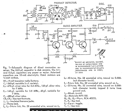
Challenge Accepted! Why we Designed the High-School Direct-Conversion Receiver the Way we Did

Dean KK4DAS's Beautiful DC Receiver
The folks over at Ham Radio Workbench have graciously accepted the challenge issued in our last podcast: that they scratch-build homebrew the 40 meter Direct Conversion receiver that Dean KK4DAS and I designed for local high school students. We want to help our brothers over at HRWB. For example, we may be able to supply a few of the 3D printed PTO coil forms. Here is some background information on the project.
Details on the project can be found here:
----------------------
Design Decisions in the Direct
Conversion Receiver
Why did we do it this way?
In thinking about how to design this receiver, we had to
make early design decisions on almost every stage. Here are some of our key considerations.
VARIABLE FREQUENCY OSCILLATOR:
Normally we might have used a variable capacitor to change
the frequency of this oscillator. But
variable capacitors are now expensive and hard-to-source. Our friend Farhan in Hyderabad used a simple
variable inductor for this purpose in his “Daylight Again” transceiver. The
coil form for this part could be 3D printed.
A metallic screw would vary the inductance as it is screwed in and out
of the coil.
We also decided to use the same simple Colpitts oscillator
circuit used by Farhan in his own high school direct conversion receiver. This circuit is unusual in that the feedback
capacitors are also the frequency determining elements (along with the variable
inductor). This simplified the circuit
and reduced the parts count, and proved to be remarkably stable.
For the VFO buffer we used the simple JFET buffer from
Farhan’s Daylight Again design.
Based on suggestions from other radio amateurs, we developed a simple frequency readout based on the position of the end of the tuning screw (how far in or out?).
We selected the 40 Meter band for this receiver because we
thought it would be easier to get the VFO stable on this frequency, and because
Farhan had built his receiver for 40 meters.
MIXER:
At first we hoped to use a simple singly-balanced mixer
using two diodes and a single trifilar transformer. But we found unacceptably high levels of AM
breakthrough (mostly from Radio Marti on 7335 kHz) when using this
circuit. So we switched to a diode
ring. This required two more diodes and
an additional trifilar transformer. We
believed the students would have great difficulty building and installing two
trifilar transformers so early in their building experience. So we used transformers that had been wound
in Hyderabad by a women’s collective employed by Farhan, and developed
a scheme for fool-proof installation of these transformers.
We also found that the mixer needed a diplexer at its output
– this would provide a 50 ohm termination at all frequencies and would result
in much cleaner action by the mixer and greatly reduced AM breakthrough from
Radio Marti. We used the same circuit
used by Roy Lewellen W7EL in his Optimized Transceiver circuit.
BANDPASS FILTER:
This was the simplest board in the project but it required
the students to wind two coils on toroidal cores. A simple dual-tuned circuit design would be
sufficient. We used component values
from the QRP Labs website. We showed
them how to wind the coils, and made a video about the technique. Students used a simple Vector Network
Analyzer (Nano VNA) to tune the filter.
AUDIO AMPLIFIER:
We had to make several design decisions here. First, we rejected the idea of using an IC
amplifier like the ubiquitous LM-386. We wanted this to be a completely analog
and discrete component experience. Then we rejected the idea of using a
push-pull output circuit. While this
would have eliminated the need for an audio output transformer, it would have
resulted in a more complicated circuit. In the end we opted for three simple
RC-coupled common-emitter amplifiers with an audio output transformer. There was no feedback in these circuits. We found there is a lot of gain (hFe)
variation in the 2N3904 transistors that we used. Care needs to be exercised in making sure
that transistors of moderate (but not too high) gain are used.
This AF amplifier chain probably presented a 1500 ohm
impedance to the mixer (instead of the desired 50 ohms), but we think this
problem may have largely been taken care of by the diplexer.
We found some very small (one square inch) speakers that
could be easily used in this circuit.
ANTENNA:
While the students could use a wide variety of antennas, we
recommended a simple ¼ wave antenna with a ¼ wave counterpoise. We thought that this antenna – of only 33
feet in length would provide good performance with low complexity, and would be
well suited to the “upper floor bedrooms” from which many of the students would be listening. Also, this antenna would not require the use
of coaxial cable or an impedance matching transformer. We made a video on how
to build and use this antenna.
POWER SUPPLY:
We opted for the use of 9 volt batteries. This proved to be a safer and wiser choice that
limited the kind of mayhem that could occur should a variable voltage supply be
used.
Details on the receiver can be found here:
https://hackaday.io/project/190327-high-schoolers-build-a-radio-receiver
May 29, 2023
Tuesday, December 3, 2024
Pil Joo's Homebrew Superheterodyne Ham-Radio Receiver

It is just very cool to see someone build a superhet and get it to work. For so many years amateurs were told that "homebrew receivers are too hard." Even simple regens or direct conversion rigs were sometimes seen as beyond the abilities of amateurs. But here we see another reminder of this not being true. Even a superhet -- which is a lot more difficult than a direct conversion receiver -- can be homebrewed by an amateur builder. Three cheers for Pil Joo!
He wrote on the SolderSmoke Facebook page:
I finished my first super het receiver. It's for the 40m band. It consists of: bandpass filter, tuned amp, diode ring mixer, wide band amp, crystal ladder filter, wide band amp, then SA602 + LM386 combo. I learned tons as i put all the components. First two amps are my design. The third amp is bga2866. The bandpass filter is what i posted a few days ago. I planned to make another one but with 2.5db insertion loss i thought it was good enough.
The result is actually quite good. I can hear everything a local kiwisdr can hear. Now, I have lots of ideas about how i can improve, but that will be another radio.

Pil Joo
Sunday, December 1, 2024
A 40 Meter Direct Conversion Receiver from M0NTV -- With some SolderSmoke Comments
Nick's video appears above.
First, let me say FB Nick. It is nice to see you making use of the AGC amp designed by Wes and Bob, using the board from Todd's Mostly DIY RF, using a mix of homebrew pads and Me-Squares from Rex, and finally the Franklin Oscillator that we spent so much time talking about on SolderSmoke.
But here are some comments:
-- I still don't think you need that RF amplifier in front of the mixer. And I suspect you would be better off without it. We did not use one in our high school 40 meter project, and never missed it. In fact, on one version of the high school receiver I even put in a simple 10k pot as an attenuator (no RF amp). Even up on 20 meters, I do not have an RF amplifier ahead of the diode ring mixer on either of the Mythbuster rigs I have built. Nick, maybe experiment a bit more and try the receiver just going from the BP filter into the mixer and see what happens.
Note that Wes W7ZOI DID NOT have an REF amp ahead of the diode ring mixer in his original 1968 40 meter Direct Conversion receiver (the one that launched the solid-state DC recevier revolution):
-- The Franklin oscillator is an interesting, but complicated circuit. The gimmick is, well, gimmicky. Here is the thing: You can achieve similar levels of stability using simple conventional, single transistor oscillators. We dispensed with the variable capacitors, and used PTO--style variable inductors. They worked fine. This Franklin oscillator still does seem to drift a bit, right? I would ground the board to the inside of the metal box.
I would also try putting all the stages on a single ground plane. This might help.
Friday, November 29, 2024
Charlie "Red" NJ7V Builds an Oscillator -- Manhattan Style

https://www.youtube.com/shorts/7t_E5N4CQxg
Red did a nice job building, then explaining, this 18 MHz crystal oscillator. I especially liked his use of Manhattan techniques, and the way he explained his effort to make the new circuit work. Too often builders expect a circuit to work right away. This often doesn't happen, and the new circuit requires some troubleshooting. Red did this with this circuit and got it working.
Red has a nice YouTube channel: https://www.youtube.com/@RedSummitRF. It is focused on POTA, but we hope it has more and more homebrew stuff like this.
Thanks to Rogier PA1ZZ for sending me this.
Tuesday, November 26, 2024
The Importance to Bell Labs of Lunch or Breakfast with Harry Nyquist -- "The Communicator" -- Bimonthly Publication of the Surrey (British Columbia) ARC.


This is a good sample (!) of the great content to be found in "The Communicator." This is the bimonthly publication of the Surrey (British Columbia) Amateur Radio Club. You can find the publication and digital back issues here: https://ve7sar.blogspot.com/
There is a lot of great material in this publication.
Monday, November 25, 2024
Pete N6QW Has Hybrid Rig On-The-Air

Sunday, November 24, 2024
Oscar 7... and Oscar 11 (aka UoSat-2)? Did Oscar 11 do much the same thing as Oscar 7?
Above is a pretty good video by Retro Rockets. Some will quibble about the technical details presented, especially about early radio, but I think the video does a pretty good job of describing the early production of ham radio satellites.
As I watched this video however, I started to wonder if OSCAR 7 was in fact unique in coming back from the dead. Back in 2018, I watched signals from OSCAR 11 (aka UoSat -2) as it tumbled through space with its battery dead, powered by a direct connection to its solar panels:
This was what Retro Rocket said was Oscar 7's claim to fame, right?
In both cases, what happened was pretty cool, but did OSCAR 11 sort of repeat the supposedly miraculous rebirth of OSCAR 7?
Friday, November 22, 2024
Sam WN5C uses ChatGPT as an Emergency Elmer

Sam WN5C has been on the blog before. Last year we covered his heroic use of a Michigan Mighty Mite at Thunderbird State Park: https://soldersmoke.blogspot.com/2023/06/sam-wn5c-builds-michigan-mighty-mite.html
This time, Sam writes about a good ham radio use for ChatGPT:
Hope you’re doing well. Just a quick note: ChatGPT is turning out to be a great homebrewing tool for me.
My elmer has been swamped with family issues, so my basic questions (“can you explain this circuit for me”) and hard questions (“why doesn’t this circuit I built work?!”) that he usually responds to right away has been a bit delayed. I’m in the process of designing a 5-band QRP CW transceiver with a superhet receiver and SSB receive so I’m learning a bunch of new circuits.
I’ve hated the idea of AI as someone who writes a lot (it cheapens what I’ve spent my career trying to perfect!), but man it is smart. I can ask it all kinds of questions. For example, it helped me design a little IF amp last night and ensured I got my impedance matching right (it’s great for mashing up lots of circuits and ensuring they work together). I can ask it for suggestions on part types and values. It helps with Arduino code if you’re into that. You can use plain language but it does well with heavy jargon. And, which I find really cool, it will step you through troubleshooting. It teaches the math, too.
Anyway, you or your readers might find this helpful. Especially when one is building at 3 AM and needs an answer immediately.
------------------
Thanks Sam!
Tezukuri and Chappy Happy -- Amazing Videos on Homebrew Radio (from Japan?) - Another 40 Meter Direct Conversion Receiver
So around the time we were building 40 meter direct conversion receivers, someone else was doing something similar. His product (above) is a lot nicer than ours. He has an S-meter and a digital frequency readout. But like ours, his is built on a wooden board. FB OM.
If you want to see what a direct conversion receiver can do, watch his video (above).
I was really amazed to see him use a modified VFO from a Kenwood TS-820. Not long ago Pete N6QW spotted one of these on e-bay and recommended that I buy it. As with the Yaesu FT-101 VFOs, we bought it for the gears and reduction drives but ended up with the entire VFO circuit. I now have one on my shelf, ready to go. TRGHS.
We are not sure who Chappy Happy is, but "Tezukuri" means "hand-made" in Japanese. The writing in the video descriptions are in Japanese, then Chinese.
Here is the YouTube channel. Amazing stuff here: https://www.youtube.com/@chappyhappy3675 He is clearly a ham. He even works on an old S-38. Who is this guy?
Thursday, November 21, 2024
Basic Radio Circuitry -- a 1971 film
This 1971 training film is pretty good. I like how they break the RF circuitry into just four components, then describe the AM receiver stage by stage. The way they handle diode (envelope) detection is exactly right. But their description of how mixing moves the incoming signal from the broadcast band to the IF is overly simple, and sort of just repeats the hetrodyne story from music. Real mixing is, of course, more complicated than that, but too complicated for a 15 minute film.
Tuesday, November 19, 2024
Bill N2CQR Appears as a Guest on the Ham Radio Workbench Podcast

Partly in an effort to make ammends for some overly harsh comments I made about the podcast's approach to the "rejuvenation" of old radios (it turned out to be overly digital for me) I appeared earlier this month on the Ham Radio Workbench podcast. It was a lot of fun. They are a great bunch of guys. And I think we had a great discussion of homebrewing and HDR in the modern era. We talked about Jean Shepherd, Farhan, G-QRP, kits vs. homebrew, homebrew vs. commercial, SDR rigs, the sBITX, the NORCAL 40, the Gilbert Cell Mixer, our experience (bad) trying to get high school kids to build a DC receiver, and many other topics.
Thanks George! And thanks to the entire Ham Radio Workbench crew!
Remember, SolderSmoke has issued a challenge to the HRWB team: We challenge them to build the 40 meter Direct Conversion receiver that we designed for our local high school. We urged them to build it the way we designed it -- avoid the temptation to substitute stages, or use pre-fab circuit boards. Build the four stages Manhattan style and get the receiver working on 40. Here are the details on how we did it. Here are our building documents:
https://hackaday.io/project/190327-high-schoolers-build-a-radio-receiver
The challenge has been issued. The gauntlet is on the ground. Go for it HRWB! Put those workbenches to use!
Saturday, November 16, 2024
Video -- Mythbuster II Rig Gets a Front Panel -- Circuit Build Almost Done
Yesterday I built a front panel for my Mythbuster II 20 meter SSB transceiver.
I used 1/8 inch plywood available from Amazon.
I cut holes for the main tuning knob and dial, for the AF gain control, for the mic plug and for a 6 figure PLJ PIC frequency counter. This gives me 100 Hz read capability, but I can hit the lower button on the counter to get 10 Hz reolution. This may help when the other guy complains bitterly that I am 40 Hz off frequency. The counter added noise to the receiver, but I was able to knock this down completely with a resistor and a cap on the power line to the counter.
I put copper tape on the inside of the panel.
I added a reverse polarity protection circuit. I now sleep more soundly.
I increased the size of the heat sink on my RD06 final. This decrease the danger of blowing up this device.
I added a jack for the connector that will switch the outboard .1 kW linear from R to T.
Video above. Comments welcome.
Thursday, November 14, 2024
FDIM 2024 Interview with Farhan VU2ESE

Thanks to Bob Crane W8SX we have some great interviews with those who made presentations at the Four Days in May event (FDIM 2024). Sorry for the long delay -- it is all my fault, but I have excuses. Our thanks to Bob W8SX, our correspondent at the FDIM event.
Here is the interview with our friend Farhan, VU2ESE, the ham who has brought so much homebrew goodness to the hobby, starting years ago with the BITX 20 schematic.
http://soldersmoke.com/FarhanVU2ESE.mp3
Thanks Bob! Thanks Farhan!
Wednesday, November 13, 2024
SolderSmoke #254 (Audio and Video Versions): Australian Hex Beam Eaters, Fake Wires, Hybrid Rig, Antennas, Mythbuster II Transceiver, Mailbag

Hex Beam Eater
November 13, 2024
SolderSmoke Podcast #254 is available:
Audio Version here: http://soldersmoke.com/soldersmoke254.mp3
Video Version here: https://www.youtube.com/watch?v=ZiZwWY1CQgI
Opening: Disturbing news from Australia! VK5RS reports that his Hex beam was EATEN by Cockatoos! So stop whining about your HOA problems, OK? It could be much worse!
FAKE WIRES FROM CHINA! Oh no! Even the wires? There is a good video from Mattias. I have it on the SolderSmoke blog. https://soldersmoke.blogspot.com/2024/11/clip-leads-made-with-fake-wire-buy-good.html Important to note that Parts Candy doen't have this problem. Buy your test clip leads from our sponsor, Parts Candy. Link in the column on the right or go to partscandy (that's one word).com
Bill's appearance on the Ham Radio Workbench. (Bill made some overly harsh comments about radio rejuvenation, and was trying to make amends.) But now we throw down the gauntlet. WE CHALLENGE the HRWB guys to build -- to homebrew - our TJ DC RX. They will experience JOO, JVO and the elite status that comes with having built their own ham radio receiver. And if they go on to build a 10 minute transmitter, they can use it for CW contacts. Like on POTA (Thomas!)
Anniversary approaching: In August 2025 we will mark 20 years of the SolderSmoke podcast. And we have already passed TEN YEARS OF JULIANISMO! Pete joined the podcast on May 26, 2013. Thanks Pete!
Question for the group: Which SSB transceivers did Doug DeMaw build?
Pete's Bench: Thermatron-Transistor Hybrid Goodness. https://n6qw.blogspot.com/2024/10/blog-post_20.html
Dean's Bench: The new Hex Beam (watch out for Cockatoos!) Now that Dean and I both have Hex Beams, we plan on pointing them at Southern California in an effort to talk to an elusive RADIO GENIUS. Stay tuned!

Dean's Hex Beam -- A Thing of Beauty
Also homebrew random wire with T match tuner for attic. RF Burns!
SHAMELESS COMMERCE: Please link to our blog and podcast! Please become a Patreon supporter (I have been posting special content there). Be sure to make use of the great boards, parts and kits available at Mostly DIY RF. Still use the Amazon link on the SolderSmoke blog page.
Bill's Bench: The new Mythbuster II (20 meters only). Built in about 3 weeks. On-the-air, while still on the bench! Worked Euope and South Africa QRP. https://www.youtube.com/watch?v=6o9QerQ7jzg
Getting another CCI amp for the Dominican Republic.
MAILBAG:
-- Paul VK3HN, talks about the nice sound of the Mythbuster II's receiver, and a new QRP rig from Dave Benson K1SWL.
-- Rick N3FJZ sent some very kind words in support of the SolderSmoke podcast. Thanks Rick.
-- Chris KD4PBJ sent us a very nice message. Thanks Chris.
-- Kevin from Belgium sent a nice blog post in support of SolderSmoke.
-- John WB4BTL spotted his old call (from 1974) in my Novice Log.
-- Dave KD2E spotted his Novice call in my Novice log: WN2TBB. He also saw a good friend WN2EHE.
-- Mehmet who has the awesome and useful WEBSDR of NA5B helped me with a Facebook problem. Thanks Mehmet!
-- Mike WN2A asked about the Yaesu FT-101 9 MHz VFOs.
-- Phil W1PJE (from MIT!) writes about old broadcast radio shows. And some really nice words of encouragement.
-- Grayson KJ7UM sent kind words of encouragement, and great background on hybrid rigs.
-- Peter VK3TPM writes about the decline of blogging, but notes that blogs are useful repositories.
-- Todd K7TFC sent me some additional Mostly DIY RF boards. Thanks Todd!
-- Ed DD5LP/G8GLM Kind words on SolderSmoke, nice info on the G-QRP 50th edition.
-- Bill AH6FC Encouraging words and good info on solar. Mahalo Bill!
-- Michael AG5VG Building LC VFOs for 7 MHz. FB OM!
-- Bob K7ZB An EE who likes the treatment of mixers in the SolderSmoke book.