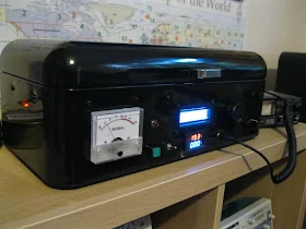
Hack-A-Day carried a very nice video describing recent efforts to turn Hans Summers' amazing QCX CW monoband transceiver into a multi-mode, multi-mode (including SSB) rig (see above). This is project will greatly interest QCX and SDR fans.
But I wondered how much of the old QCX is still there after the modification. Not much, it turns out.
Here is the bloc diagram of the QCX. It is essentially a phasing rig, using the same principles as my venerable HT-37 transmitter and my version of KK7B's R2 receiver:
Yesterday Paul VK3HN sent me the schematic of the new multi-mode, multi-band version:
Notice how different it is. I thought that perhaps the new rig would keep something of the I-Q circuitry of the QCX, but it does not. This is not a criticism, just an observation.
But here is something that harks back to a topic we've been debating on the blog and podcast. Notice that the top diagram is a bloc diagram. There is a lot of circuitry in most of those boxes -- lots of resistors, capacitors, inductors, and transistors. There is a schematic diagram under that bloc diagram. But look at the second diagram. While it looks like one, that one is NOT a bloc diagram. That IS the schematic diagram. Most of the circuity has been sucked into the chips.
While many will prefer the rig described by the second diagram, I remain an HDR guy, and don't really like seeing the circuitry disappear into the ICs. But, to each his own. This is all for fun. Congratulations to the guys working on the new rig.


