Podcasting since 2005! Listen to Latest SolderSmoke

Showing posts sorted by relevance for query BITX Instability. Sort by date Show all posts

Friday, June 5, 2015

BITX DIGI-TIA Build Update #7: On The Air!

 
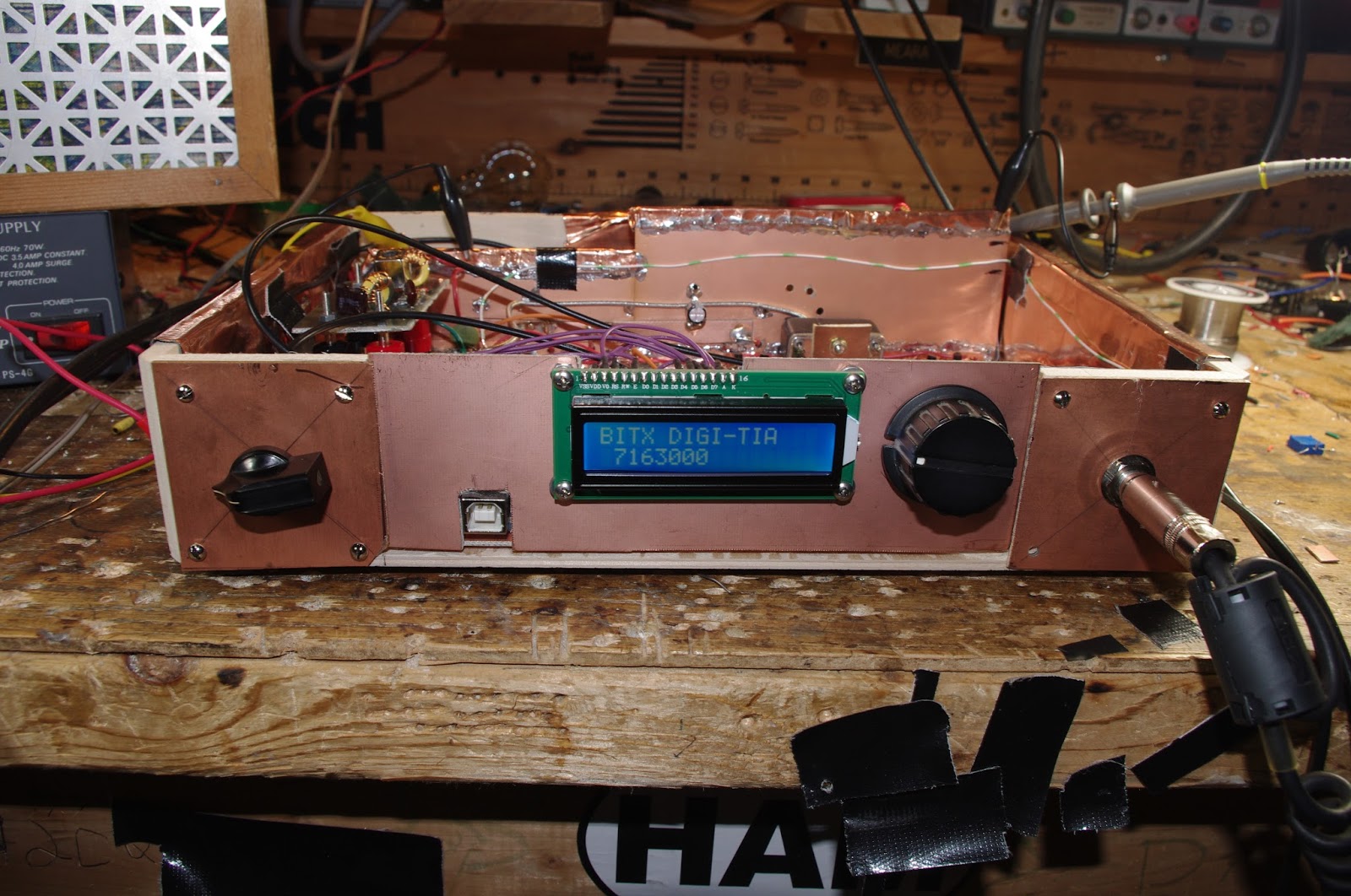
With lots of encouragement from Pete, I finally got the BITX DIGI-TIA on the air.  The first contacts were made yesterday. I have it on 40 meter SSB.  The finicky denizens of that audio-conscious band seemed to like the sound of the rig.   I was almost reluctant to tell them it is homebrew (no need to stir up trouble!)
 
The plug in filter arrangement seems to work very well.  This will allow me to put this rig on many other bands.  All I have to do is build some additional filter boards and upload modified versions of the software.  There is even space to make a plug-on socket for the crystal filter (the 9 MHz IF would not be cool for 17 meters).  
 
I'm really pleased with the RF power chain (the original BITX chain).  This time I built it all in a straight line along the back of the transceiver with lots of attention to shielding and grounding.  There were no instability problems.  The amplifiers did not try to be oscillators.  I was shocked!
 
I did have to reduce the gain of the three termination insensitive transmit amplifiers. Using the chart in the 2009 Wes Hayward/Bob Kopski article,  with just a few resistors you can set the gain.   I had built them with 19.4 db gain each.  This turned out to be too much -- the slightest amount of audio into the SBL-1 was driving the amplifiers to peak output.  So yesterday I changed all three amps to 15 db (I think that was what Farhan had in the original BITX).  It only took me about 15 minutes and it seemed to take care of the problem.  I am getting 7 or 8 watts out of the IRF-510.
 
T/R switching is very smooth and quiet using just two small 12V relays.
 
Thanks to Pete for the mil-pad boards and the encouragement (especially on the use of the Si5351).  Thanks to Farhan for the BITX architecture. Thanks to Steve Smith for the Yaesu filter.  Thanks to Wes and Bob for the TIA circuit.  Thanks to Thomas in Norway for the Si5351 software.  And Thanks to Allison for all the good advice.


Our book: "SolderSmoke -- Global Adventures in Wireless Electronics" http://soldersmoke.com/book.htm Our coffee mugs, T-Shirts, bumper stickers: http://www.cafepress.com/SolderSmoke Our Book Store: http://astore.amazon.com/contracross-20

Wednesday, October 16, 2013

Yikes! Screeching Transistors Throwing off Blue Light!


I found a quote from Doug DeMaw that I wanted to share.  This one seems appropriate as I struggle with unwanted oscillation (and as Halloween approaches). From the January 1986 QST:

"Self -oscillation occurs not only in the low-frequency and high-frequency spectrum, but it often takes place at audio frequencies!  I have actually heard the transistors "screeching" when strong audio oscillations were taking place in a homebrew transistor power amplifier. On one occasion I could see a bluish glow coming from within the transistors (visible through the ceramic heads of the devices) during a period of instability.  Needless to say, the transistors self-destructed."

I've been having some instability problems with my BITX 17 IRF510 final.  But I think I have the problem identified.  I was getting low frequency oscillations (around 100 KHz).  Tonight  tried putting the IRF510 on a separate power supply.  The oscillations ceased and I am getting a nice clean 3 watts out.   So I'll go back and beef up the decoupling on the power supply lines.


Our book: "SolderSmoke -- Global Adventures in Wireless Electronics" http://soldersmoke.com/book.htm Our coffee mugs, T-Shirts, bumper stickers: http://www.cafepress.com/SolderSmoke Our Book Store: http://astore.amazon.com/contracross-20

Monday, January 27, 2014

BITX20/40 Update #6: 20 Meter Exorcism


The transmitter was working fine on 40, but was horribly unstable on 20. In the past, this kind of thing would really drive me nuts, but experience has made me more patient. I know that "taming the beast" is part of the homebrew process. 

I knew that layout was part of the problem:  I had significantly less room on the board with this rig than I'd had with the BITX17:  the additional bandpass filter and low pass filter, and the associated relays, used up a lot of copper clad real estate. So by the time I built the PA chain, the inputs were too close to the outputs.

The fact that the rig was stable on 40 but not on 20 led me to believe that this was not a problem of insufficient decoupling.  Instead, I thought that I was getting additional inductive feedback at the higher frequency.

I noticed that the instability disappeared when I put the 1X scope probe on the input to the first amp in the RF chain (Q14). That was an important clue.  Looking closely at the circuit, I realized that the base of Q14 had a long lead (several inches) up to the low pass filter.  I had experienced problems with this lead on the BITX 17 project and had cured it with a relay at the low pass filter -- this relay took one end of the lead out of the circuit on transmit, preventing it from becoming a little radiator.  I used that mod in this rig, and figured that that cured the trouble.  Wrong.   The other end of that lead was still connected to the input to the RF power chain.  It was picking up enough RF to send the PA chain into oscillation.

I put a SECOND relay at the other end of the line.  That took it completely out of the circuit.  And the instability disappeared.  I fired up the rig and worked California on 20.  Very satisfying.   

Our book: "SolderSmoke -- Global Adventures in Wireless Electronics" http://soldersmoke.com/book.htm Our coffee mugs, T-Shirts, bumper stickers: http://www.cafepress.com/SolderSmoke Our Book Store: http://astore.amazon.com/contracross-20

Friday, August 7, 2015

Amplifier Woes! Instability at Low Drive Levels! (Video)


I have to keep reminding myself:  This is not "plug and play." These are not appliances. 

After I got my 40 meter problems squared away,  I was doing some testing on my beloved 17 meter BITX.   I noticed something weird:   With the CCI EB63A amp feeding my 17 meter Moxon antenna, as I raised the output of the BITX17 driver, at one point (at about half the max input power) the SWR would suddenly spike. Then, as I raised the drive level above that point, the SWR would go back to normal. 

I looked at it on the 'scope.   I can see the signal go very ugly at the mid-level drive point.  In the FFT display, I can see that there is a strong signal at around 435 kHz.  The 18 MHz signal seems to be riding along on top of it.  Take a look at the video above.

Additional clues: 

I see no signs of the 435 kHz signal at the output of the BITX 17.  It seems quite clean.

This problem disappears if I replace the Moxon with a dummy load. 

This problem does not show up if I feed the EB63A with my almost identical BITX20.   And I use the same LP filter on both 20 and 17 in the CCI amp.

Any suggestions?  Has anyone had this kind of problem? 

Allison and Pete have been helping me with this.  Thanks to both of them.  

Our book: "SolderSmoke -- Global Adventures in Wireless Electronics" http://soldersmoke.com/book.htm Our coffee mugs, T-Shirts, bumper stickers: http://www.cafepress.com/SolderSmoke Our Book Store: http://astore.amazon.com/contracross-20

Friday, April 17, 2020

Walter's VFO

Main VFO board under plastic -- buffer board off to the right
There is a lot of tribal knowledge in this short article by Walter KA4KXX.  (The most recent issue of SPRAT has a picture of a SPRAT cover from more than 30 years ago, announcing an article by Walter.  OM has been at this for quite a while.)  Walter's advice is similar to that of Doug DeMaw, especially on the air-core coil.   FB Walter,  thanks for sharing.  

Regarding the last line in Walter's article, please direct any complaints about drifting analog VFOs to Peter Juliano.  He will be delighted to receive these complaints, and will promptly provide all correspondents with very succinct advice on how to overcome the instability.  

My Way to a Low-Drift Analog VFO, by Walter KA4KXX

I recently built a digital VFO (from a QRP Labs Kit) to see what everybody is talking about, and it has been quite handy for my first two-band homebrew transceiver, but by the time one adds the low pass filter, a low-level RF amplifier to boost the weak output, a 5 VDC regulator, and a hefty +12VDC power line filter to the beast to keep the digital noise out of the rest of the radio, for a single band project I still prefer a low-drift analog VFO.  

My approach to minimizing drift is very simple and works well for a VFO range of 3 – 7.3 MHz, which is all that is needed for the 20 to 80 Meter bands, either direct conversion (adding a doubler for 20M) or single conversion with approximately a 10 MHz IF.  

First, see my schematic (adapted from Small Wonder Labs 40+ transceiver, original BITX40 Analog VFO, and other sources) and wind an air core inductor with stout magnet wire such as 24 or 22 AWG.  Use a thick, rigid plastic form of a diameter so that you need about 12 turns, and single coat with water-based sanding sealer, Q-dope, or similar.  Use hot glue to mount the coil firmly to the single-sided circuit board, and build a cover of some type, especially if the radio is to ever be used outdoors.
   
Second, all the VFO capacitors (except power supply bypass) should initially be the modern C0G type, which can be obtained from Mouser (such as TDK FG28C0G1H681JNT06 or the like), which I trust more than those labeled NP0.

Then, power up the VFO and tweak the coil, tuning arrangement, and range capacitor to get the frequency range you desire.

Next, monitor the drift from a cold start to see how fast it is moving as it warms up, and whether it stabilizes nicely (my goal for SSB Phone use is less than 20 Hz drift during any 10 minute period) after 10 – 15 minutes maximum.  If it does not stabilize to your satisfaction, then start substituting polystyrene caps for the C0G units one at a time until you are happy with the performance.

[Also remember that a stable BFO is important as well, and if you use the BITX 40 crystal oscillator design, I recommend installing a dedicated 78L09 power line regulator.]

If you build this VFO at the higher (7 MHz) frequency end, just change the inductor value to about 0.5 uH, with everything else about the same, but expect to do more tweaking to get stability, and the warm-up time may be closer to 15 minutes.  After years of experimenting, this is what has worked for me.  If it works for you, please send me an email (see my QRZ page) of thanks.  If not, file a complaint with Soldersmoke. 


Designer: Douglas Bowman | Dimodifikasi oleh Abdul Munir Original Posting Rounders 3 Column