Serving the worldwide community of radio-electronic homebrewers. Providing blog support to the SolderSmoke podcast: http://soldersmoke.com
Podcasting since 2005! Listen to Latest SolderSmoke
Wednesday, December 3, 2025
Thursday, February 6, 2025
SolderSmoke Direct Conversion Receiver Challenge: A Short Video from Dean about the Virtues of Building the AF Amplifier ONE STAGE AT A TIME
Dean will soon post his longer video on how to build the fourth and final board of the SolderSmoke Direct Conversion Challenge receiver, but we know many builders are chomping at the bit, and are going ahead with the building of the AF amp board. We hope that this short preliminary video will help. Here Dean descibes the benefit of building the three stage amp, ONE STAGE AT A TIME.
Response to the challenge has been great. There are at least 30 receivers under construction around the world. Many are already inhaling RF. All of the problems that arise with true homebrew are being identified and fixed. Dean's full AF amp video will be out shortly. Thanks Dean!Saturday, November 2, 2024
More Background on the Mythbuster II Rig (and a short video)
Above is a short clip of me hearing an old friend on the new receiver. TRGHS.
A couple of guys on Facebook asked for a schematic for this rig. I don't really have one -- as you will see it is a collection of different circuits from lots of different sources. I was also thinking that if you need a schematic for a rig like this, you probably shouldn't try to build a rig like this. But in an effort to be nice, I supply here some background info on some of the circuitry and parts sources. And no, I don't have BOMs nor Gerber files.
More info on the Yaesu VFO is here:
https://soldersmoke.blogspot.com/2021/07/mythbuster-video-3-using-vfo-from-yaesu.htmlAs for the tape, I got mine from Amazon. It has conductive adhesive:
https://www.amazon.com/gp/product/B07QQJ4MX1/ref=ppx_yo_dt_b_search_asin_title?ie=UTF8&psc=1
Wednesday, October 30, 2024
Bill N2CQR Builds Yet Another Mythbuster Transceiver
This one is for 20 meters (no need for 75) and will go to the Dominican Republic.
6 crystal filter at 5.2 MHz. VFO from old Yaesu FT-101 Termination Insensitive IF amplifiers using boards from Mostly DIY RF No RF amp ahead of the mixer. First mixer is homebrew diode ring. Bandpass filter has 4 LC circuits. Steep skirts. Low insertion loss. Bal Mod/Product detector has two diodes (singly balanced) Carrier osc is crystal controlled and homebrew. Audio amp starts with a 2N3904 amplifier followed by an LM386 board. Transmitter portion will be done next.Friday, September 29, 2023
"The Art of Electronics" #8 -- Why Not a Simple Emitter Follower as The AF Output Circuit?
Back when Dean KK4DAS and I were trying to find a suitable AF amplifier circuit for our High School Direct Conversion receiver project, we were debating what to use as the final. One option was the standard NPN-PNP push-push amplifier (like in Figure 2.53 above) -- an advantage with this one was that it would not require an AF transformer. But we decided that this circuit would add complexity to a project that we were hoping to keep very simple.
Another option was a simple common emitter amplifier with a transformer in the collector circuit. This worked, and was simpler. We ordered the transformers.
In the midst of all this, at the local radio club hams asked us why we just didn't put a single emitter follower at the output to handle the impedance transformation to an 8 ohm speaker (sort of as in Figure 2.52 above). They were convinced this would work. I was not so convinced and pointed out that we had never seen such a circuit in any of the ham radio literature. If this could be done, why hadn't the likes of Doug DeMaw and others used this circuit in their many, many rigs?
This discussion kind of ended there (we opted for the common emitter transformer circuit), but I have thought about it from time to time. A couple of weeks ago, when I got the second edition of The Art of Electronics, I found the above discussion of the use of this kind of emitter follower circuit. You can see why this circuit has not been used. Just to be sure, I built one in LTSpice. Sure enough, it takes way too much current.
Thank you, Horowitz and Hill!
Sunday, May 14, 2023
SolderBaloney and SolderTruth
Saturday, March 25, 2023
Update on the High-School Direct Conversion Receiver Project: Board #4 Completed
This week we had two sessions of about two hours each. We introduced the final board: the audio amplifier. Many of the students began work on this amplifier; others were catching up with work on boards presented earlier.
The AF amp is their most challenging board: It used 14 Manhattan pads and about 26 components. We warned the students that amplifiers often aspire to be oscillators. We told them to pay attention to layout, and to keep their leads short.
At first, the students just built the first stage on the AF amp board. They tested this, then moved on to build the other two stages.
By the end of Friday, two groups had completed the build of the AF amplifier board.
We think there are about 13 receivers in production. Some are near completion, others will need more work.
On Thursday of next week those teams that have completed all four boards will put the circuits together and will test the entire system. They will then add all needed front and back panels and socketry.
We really want the students to complete as many of these receivers as possible. Exam season and the end of the school year is approaching, so we have to get this done. We will remind students that they don't want to that person who ALMOST finished a project! We will urge them to GET IT DONE! They can tweak it and mod it later. This kind of tweaking and modification is part of the homebrew experience.
We have been presenting awards to the students who are first to complete each stage: The winners of the PTO board competition got a copy of SolderSmoke: Global Adventures in Wireless Electronics. Those who won the mixer competition got a W1REX Hamfest Buddy transmitter. Thanks Rex! And this week we presented an award to the students who were the first to complete their bandpass filter. You've heard of the Tony, the Emmy and the Grammy? Well, we presented "The Torry" (from Toroidal). The trophy was made from a toroidal winding tool made in Alaska by KL7FLR. I explained to the students who had made it. Thanks Paul!
Monday, November 21, 2022
A Homebrew LM386 -- Does Anyone Want to Build It? Help Save Us All from the Indignity of ICs!
Wednesday, April 13, 2022
The 17 & 12 SSB Transceiver -- Circuit and Build Info -- Video #4
Monday, November 8, 2021
Save $2970! Build this $30 DIY Microphone!
Friday, April 30, 2021
Trying to Repair Some Old Gear, He Got Hit with a Dose of LSD!
Oh no, here's something else for us to worry about when working on old gear. As if the treat of electrocution or radioactive poisoning were not enough, now we have to worry about being hit with a dose of the 1960's drug culture. That could be one bad trip indeed. Imagine if you were having a hard time troubleshooting the Buchla Model 100. All of a sudden things start getting weird and your test gear starts dancing on the bench.
Fortunately, this is not likely to happen with a rig like the DX-100. With rigs like that the only similar danger is nicotine poisoning.
Thanks to Stephen Walters for finding this groovy story.
Sunday, January 24, 2021
VBE Multiplier Makes KLH Receiver "Cool Running"
Yesterday I turned to the SolderSmoke wizards for advice on how to fix my KLH Model Twenty-one II FM receiver. I had finally gotten the thing working -- it wasn't the speaker, it was the AF amp, probably one of the final transistors was blown. I replaced the finals and the driver. For the finals I used a TIP29C and a TIP30C. For the driver a 2N3906. With this fix the receiver was sounding good, but the heat sink on the AF amplifiers was way too hot.
If you look at the comments in yesterday's post, you will see some great suggestions on how to fix this problem. The comments and Google led me to Alan W2AEW's YouTube channel and his video on a circuit called the VBE multiplier. Voltage Base-Emitter multiplier. I'd never used this circuit before. It allows you to adjust the bias on the bases of the two transistors in a push-pull amplifier.
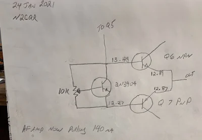
This morning I built the circuit on a small piece of PC board. There were just two components: a 10k trimmer pot and a 2N3904 transistor.
With the little board installed, I adjusted the pot for a 1.2 volt difference between the bases of Q6 and Q7. I ended up with base voltage values almost identical to those called for in the KLH schematic.
The receiver sounds very nice now, and is no longer on the verge of bursting into flames. I even made up my own version of the pillow that KLH claimed was necessary for proper acoustic suspension.
Sometimes it is nice to be able to listen to something other than the chatter on the ham bands. And it is fun to do so with a receiver that you have worked on.
I even used some Desitin as a substitute for heat sink compound.
Thanks to Rogier for the receiver, to ZL2DEX, K0EET, W2AEW and David McNeill for the good advice. And to Dale K9NN who sent me a box of parts from which emerged the 10k pot I used in this project. Thanks guys. 73
Tuesday, May 12, 2020
An Understandable Chip: The LM386
So, I don't use voltage regulator chips -- I use Zener diodes. I prefer analog LC oscillators to AD9850s or Si5351s. And I have repeatedly built discrete component audio amplifiers when most normal people just put an IC AF amplifier in the circuit.
When I built the Q-31 Shortwave AM receiver, I kind of ran out of gas at the end. I wanted to get the receiver going and I didn't want to build yet another discrete AF amp. So I used an LM386.
I rationalized this deviation from cherished values by noting that the discrete AF amplifier circuitry that I was using was remarkably similar to what exists inside the LM386. So that little chip is just as understandable as my discrete component creations. It wasn't REALLY a mysterious black box...
Around this time I found a web site that made me feel mush better about all this. It explains very nicely how the little LM386 does such a great job. It really packs a lot of amplification into a very small package. Here is the web site:
https://www.electrosmash.com/lm386-analysis
Shortly after my transgression, Jenny List over at Hack-A-Day posted a nice piece looking at the inner workings of Op-Amps. Who knows, I may seen be using 741 chips too!
Here is the Hack-A-Day piece:
https://hackaday.com/2020/05/09/an-op-amp-from-the-ground-up/
Saturday, December 30, 2017
Building the Ceramic Discrete Direct Conversion Receiver - Part 3 -- The Audio Amplifier
Friday, August 18, 2017
Voltage Regulators as Audio Amplifiers - Who Knew!?
Here's the data sheet: http://www.ti.com/lit/gpn/tl431
And here are a couple of sites that discuss this very interesting repurposing:
http://theradioboard.com/rb/viewtopic.php?t=6733
http://techlib.com/electronics/audioamps.html#TL431
Friday, January 27, 2017
When Bypass Caps are Not Enough: Active Decoupling
Next I had to find out how the OLED noise was getting into the rest of the receiver. It could have been through the SCL SDA or even the ground lines. It could have been just through capacitive or inductive coupling from the display board itself. A big clue came when I tried powering the display from a completely separate power supply: BINGO! The noise disappeared. So I knew the noise was going into the rest of the receiver through the Vc line that powered the OLED.
I had been powering the OLED from the 5V regulator on the Arduino Uno. In an effort to isolate the noise, I put a separate 5V regulator in the circuit for the OLED. No joy -- noise still there. I then tried putting an RC low pass filter between the OLED and the 5V regulator. Still had the noise. Finally I remembered something from the AF AMP circuits of Roy Lewallen, Rick Campbell and Roger Hayward. ( I think Roy was the pioneer on this one.) They all used an "active decoupler" between the first AF amp and the power supply line. I confirmed that it was my first AF amp that was picking up the OLED noise. I built the active decoupler (just three parts!) and the noise disappeared. GONE!
There are only three parts, but the way this circuit works is kind of complicated and not very intuitive. There is a good discussion of how it works here:
www.facstaff.bucknell.edu/dkelley/elec351/Lab/elec351lab5_sp04.doc
Roy, Rick and Roger were using this circuit to knock down 60 Hz AC hum, but I found that my OLED noise was at around 200 Hz -- I figured (correctly) that the active decoupler would take care of this as well. I think this little circuit can be useful in dealing with the kind of noise generated by the digi displays that many of us are now using.
David Rowe has a really interesting analysis of this circuit here:
http://www.rowetel.com/?p=4781
Friday, December 9, 2016
Great Hackaday Article on the Venerable LM386
I'm not crazy about chips, but I've come to like the LM386. It is not really a little black mystery box -- as the article points out, the internal circuitry is simple and completely understandable. So you shouldn't feel any appliance-op angst when you use one of these.
http://hackaday.com/2016/12/07/you-can-have-my-lm386s-when-you-pry-them-from-my-cold-dead-hands/


.jpg)


