Podcasting since 2005! Listen to Latest SolderSmoke

Showing posts with label SSDRA. Show all posts

Thursday, April 13, 2023

The Franklin Oscillator: A Super-Stable VFO. Why No Attention? Why So Little Use?

My Franklin VFO

Lee KD4RE of the Vienna Wireless Society has been talking about the Franklin oscillator. He has been telling us that it is very stable, and capable of stable operation up through the ten meter band.  Lee wants to build an direct conversion receiver for all of the HF bands with one of these circuits. 

I was skeptical.  First, I'd never heard of this circuit.  I'd grown up in ham radio on a steady diet of Hartley and Colpitts and Pierce.  Vackar or Clapp were about as exotic as I got.  And second, I'd come to accept that it is just not possible to build a good, stable, simple,  analog VFO for frequencies above around 10 MHz.  For example,  in his Design Notebook, Doug DeMaw wrote, "VFOs that operate on fundamental frequencies above, say, 10 MHz are generally impractical for use in communications circuits that have receivers with narrow filters."  DeMaw was known for resorting to variable crystal oscillators. 

But then this month Mike Murphy WU2D put out two videos about his use of the Franklin oscillator circuit in a direct conversion receiver at 21 MHz.   The VFO was shockingly stable.  I began to believe Lee.   I fired up my soldering iron and built one.  

WU2D's Franklin Oscillator

Lee was right,  it is in fact remarkably stable, even at higher frequencies. My build (see picture above) was a bit slap-dash and could be improved a bit, but even in these circumstances here is what I got.   This was with a stable 6 Volt Supply and with only a cardboard box covering the circuit: 

Local time                  Frequency

0543                           19.1114 MHz  (cold start)

0636                           19.1116 

0804                           19.1117

1034                           19.1118

1144                           19.1117

I started digging around for references to the Franklin.  There was nothing about it in Solid State Design for the Radio Amateur, nor in Experimental Methods of RF Design.  Pat Hawker G3VA (SK) did discuss it in his Technical Topics column in RADCOM, February 1990.  Pat gave a great bio on Charles S. Franklin (born in 1879 and a colleague of Guillermo Marconi). But tellingly, Pat writes that, "Despite its many advantages, the Franklin oscillator remains virtually unknown to the bulk of American amateurs."  

QST "How's DX" August 1947

It wasn't always unknown.   In the 1940s, we see articles about the Franklin oscillator circuit. There is a good one in the January 1940 issue of "Radio." 
 The author W6CEM notes that the circuit "is probably familiar to only a few amateurs."  It shows up in the "How's DX" column (above). And the 1958/1959 issue of Don Stoner's New Sideband Handbook we see a lengthy description of the Franklin oscillator.  Stoner wrote: "The author's favorite oscillator is the 'old time' Franklin, and it is believed to be the most stable of them all! This rock-solid device can put a quartz crystal to shame! Because it represents the ultimate in stability, it is the ideal VFO for sideband applications."  And we see a PTO-tuned Franklin oscillator in the July 1964 QST. And it is in the fifth edition of the RSGB Handbook (1976). 

Here is the January 1940 "Radio" with the Franklin oscillator article on page 41 by W6CEM: 
Here is the July 1964 QST article: 

There was an article about the Franklin oscillator in 73 magazine by W4LJC in February 1999: 
The author notes that: 


Much more recently (2022), Mike WN2A, modified his Mousefet transmitters (seen in QRP Classics in 1992) to include the use of the Franklin VFO circuit.  Mike's documentation is really excellent.  Kostas SV3ORA has a Franklin oscillator in his Super VFO circuit.  Hans G0UPL has one on his site. 


Look, there may be reasons why the Franklin oscillator has been ignored.  But the circuit sure seems to present a lot of advantages.  Stable operation beyond the 10 MHz barrier is the big one.  Simplicity is another.  If there are problems and shortcomings, let's hear about them. But it seems as if the Franklin oscillator may provide the opportunity for us to build stable VFOs beyond 10 MHz without resort to complicated PLL stabilization techniques, and without opting to go with an Si5351 or other complex digital devices.   

So let me ask:  Why hasn't the Franklin oscillator been given more attention, and why haven't we seen more use of this circuit by hams or even by manufacturers?  

Monday, April 3, 2023

Technology and Methods from Wes Hayward W7ZOI

Great stuff.  Lots of wonderful articles filled with wisdom to ponder. 

 http://w7zoi.net/oldtech/ponder.html

Thanks to Tony G4WIF for spotting this gem and alerting us.  And thanks to Wes for all of this.  


Wednesday, November 2, 2022

Understanding a Very Simple Two-Diode Mixer


Take a look at the simple little mixer above.  I think I first saw it in SPRAT.  Thinking that it was really just a simplified version of the two diode Doug DeMaw mixer that I had been using for years, I couple of years ago I built it into a little Direct Conversion receiver.  It worked great.  But later, I began to have doubts about it.  In the words of young James Clerk Maxwell, I started to wonder about "the particular go of it." 

You see, the way the DeMaw mixer is set up,  both of the diodes are simultaneously on and off.  This has the effect of "chopping up" the incoming RF at a rate set by the VFO frequency.  Boom.  Fournier.  Mixing.  Great.  


But look at the mixer at the top of this post.  Here the VFO signal is coming in on the wiper of the 1k pot. The same signal is hitting both diodes at the same time.  The diodes are not being fed differentially.  So D1 and D2 are NOT both simultaneously tuning on and off.  Instead, when the wiper goes positive, D2 turns on while D1 is off.  On negative swings of the voltage at the wiper, D1 turns on while D2 is off.  For me, this made it a "mystery mixer." 

This reminded me of the sub-harmonic DC receiver I built earlier in the year:  The VFO runs at half the operating frequency, but the diodes are set up to switch on and sample the RF TWICE each VFO cycle.  This is the equivalent of having the VFO at the operating frequency.  


Could it be that this was just a sub-harmonic mixer with the VFO at the operating frequency? (I should note that Doug DeMaw published a design that actually made this mistake.  See:  https://soldersmoke.blogspot.com/2011/07/doug-demay-and-polyakov.html ) I knew that this would sort of work, but it would not work very well.  And the mystery mixer seemed to work very well.  Hmmm. 

I was loaning the DC receiver with the mystery mixer in it to a local high school.  I worried that I was loaning them something that I didn't really understand. I remembered that I'd been trying to figure out this mixer since early 2021:  https://soldersmoke.blogspot.com/2021/02/some-thoughts-on-singly-balanced-mixers.html  

Our beloved book, Solid State Design for the Radio Amateur (SSDRA) has an explanation of this circuit on page 74.  But this explanation didn't seen to work for me.  Check it out. YMMV. 

Bottom line:  I still couldn't figure this circuit out, so left it alone for while.  

The other day I woke up and looked at it with fresh eyes.  Suddenly it hit me.  Although the VFO was hitting the diodes in the same non-differential way as is done in the sub-harmonic mixer,  the RF (signal) is entering the mixer in a differential way.  This means that the two diodes are taking turns sampling the upper side of L2, then bottom side of L2, via L1 and L2.  This results in a complex repeating waveform that is similar to that of diode ring mixer.  Within that complex repeating waveform, there are sum and difference frequencies. I did some noodling on this: 


The key difference between this mixer and the sub-harmonic mixer is the way L2 is positioned:  In the sub-harmonic mixer, there is no differential feed of the RF.  Both diodes get the same polarity of RF.  The VFO switches on D1, then D2.  The RF is sampled at twice the VFO frequency.    But in the mystery mixer that had me scratching my head, the RF is fed to the diodes in differential form.  So while the diodes here are -- as in the sub-harmonic mixer -- being switched on and off sequentially, they are taking turns sampling the top and the bottom of L2.  That provides the complex repeating waveform that we need to get the sum and difference frequencies.  In a DC receiver the difference frequency is audio. 

What do you guys think?  Do I have this right?  How would you characterize this mixer:  Is it multiplying by 1 and 0?  Or is it multiplying by 1 and -1? 

This would be good mixer for a school project.  It is simpler than a mixer with a tri-filar toroid. 

Saturday, April 24, 2021

It's an INVESTMENT!


Exactly what we've been saying about Drake 2-Bs and copies of SSDRA!  

Friday, October 9, 2020

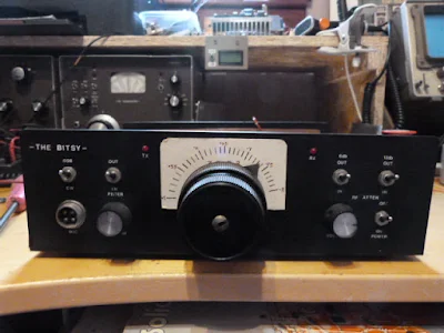
The Bitsy -- Homebrew Double Sideband from Scotland


This is such a beautiful project:  it involves DSB, homebrew, troubleshooting, George Dobbs, SSDRA, J310s, a box kite,  and ham radio nostalgia.  I was struck by how similar the Bitsy looks to some of my own DSB creations (but the Bitsy is nicer).  I'm really pleased to find a DSB project coming out of the UK -- when I was there, DSB was kind of frowned upon by spectrum preservation zealots.  I say there is plenty of room for the very few homebrew DSB rigs that will ever grace the airwaves with their presence.   Thanks John.  Have fun with all your projects.  73  Bill 

Hi Bill

In the early 80's I built and experimented with Direct Conversion Receivers and had a lot of fun with them. I came across a 40M DC cw transceiver by the late Rev. George Dobbs in a Practical Wireless magazine and decided to build it. Whether I was just lucky I'm not sure but it worked first time and I had several cw contacts with it. It was called “The PW Severn”. I then discovered DSB and looked into modifying the wee rig. I gave George a phone, no internet in those days, and explained what I was proposing to do and if there was any advice he could offer. His reply was ,  “it should work so try it and see, any problems get back to me”. It worked and I had a lot of fun with it. I used to take it portable and with a box kite to support a long wire and worked all over Europe.

It was after reading and learning about circuits and home brewing I wondered if I could design and build a DSB transceiver of my own. I had plenty of articles and most importantly a copy of Solid State Design, now well thumbed.

So the “Bitsy” was born. It is an 80M DSB transceiver. The PA produces about 2 watts. I took what I thought was the best for each module and built it using six circuit boards which I designed and etched myself. Nowadays I use the Manhattan method for one of circuits. It is much easier and quicker.

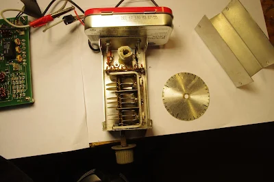
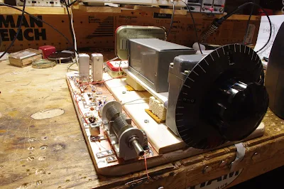
Like most home brew projects, the fun is in the building and the wee rig lived in a box for several years. Probably over 30. My doesn't time fly. I came across it again while looking through my boxes and decided to give it an airing. Expecting it to work on power up I was quite shocked when it produced nothing on both receive and transmit. After staring at it for a couple of minutes I unscrewed the lid and studied the wiring for a dry joint. Nothing so I switched on my Digital Multimeter and Oscilloscope. I soon found out that the output from the VFO was missing. The VFO uses one FET and two PNP Transistors for the buffers. The scope soon proved that the FET was faulty. I used an MPF102. These are hard to get so I replaced it with a J310. While I had the VFO out I also replaced the 9.1v zener diode, which provides a regulated voltage for the FET, with a 78L05 connecting the centre pin via a 580ohm resistor to earth. This gives me a 9.3v regulated supply for the oscillator. It is now back in full working condition.

With the Covid 19 epidemic I, like a lot of the Amateur Radio fraternity, am spending a lot of time in the shack and looking for new projects. I am buying back my old FT200 which was my first rig. An old friend and lapsed amateur has still got it and agreed to sell it back to me. It is still in a good condition for being nearly 50 years old and just needs some TLC. When it is finished it will take pride of place beside my restored Heathkit SB104A. And they say nostalgia is not what it used to be!!

John Forsyth

GM4OOU


Monday, August 24, 2020

Monday, July 27, 2020

Paul Taylor's Quarantine "Summit Prowler 7" and some Radio Archaeology


Paul Taylor VK3HN has really outdone himself in this video (above) and blog post. He describes coming across a somewhat mysterious homebrew SSB exciter with some cryptic markings on it. Paul eventually figures them out.  We still don't know who the builder VK3WAC was -- can anyone find him in their logbooks? 

As Paul goes through the description of the transceiver he built around the mystery exciter, he mentions a number of hombew heroes including Farhan VU2ESE, Peter DK7IH, Eamon EI9GQ (I have to get his book!), and Don W6JL.  Also,  our beloved SSDRA book plays a prominent role in the story. 

Paul's video is really beautiful -- at one point the camera pans the landscape and we see kangaroos in the field.  It is also refreshing  -- as we suffer in the heat of the northern hemisphere summer -- to see Paul and his friends out on the summits in their winter coats and hats.  

It looks to me as if Paul built this rig during the current emergency, so I will list it as a Quarantine rig.  Every dark cloud has a silver lining, and Paul's rig has added a bit of silver to the dark COVID cloud.  Thanks Paul. 

https://vk3hn.wordpress.com/2020/07/26/something-old-something-new-a-four-band-5w-50w-ssb-cw-transceiver-summit-prowler-7/

Saturday, April 4, 2020

Quarantine Project: An AM Receiver for the 31 Meter Band. The Q-31.


During this StayInTheShack (SITS) emergency, it is good to have something to work on.  I decided it would be best to try to build something using only items currently in my parts collection.  I've been getting into shortwave listening again, and I've discovered that the 31 meter band (9.4 - 9.9 MHz) is my favorite. Thus the "Quarantine On-Hand 31 Meter AM Receiver."  A big part of the inspiration for this project comes from the AM receiver of Paul VK3HN. 

I propose that we all designate rigs built during quarantine as "Q" rigs.  This will be the Q-31. 

I had an old chassis on the shelf.  It held my WSPR DSB rig in Rome, and various other projects over the years.  It has so many holes in it that it looks like it has been used for target practice.  

A while back Pete N6QW sent me this really magnificent variable capacitor with at least two reduction dries and an anti-backlash gear.  I've been looking for a project that will allow me to use AND display this beautiful part.  It will be the main tuning cap for the Q-39. It will stay -- like the tubes in the rigs of days-gone-by --  above the chassis. 

While in London many years ago I picked up an old regen receiver at the Kempton Park rally.  The parts are still in my junk box.  A very nice 1.7 uH plug in coil (with socket) was there.  That will be the main coil in the Hartley Oscillator that will be the VFO.  I will add a few turns for the feedback coil (see circuit diagram below).  I wonder of that Eddystone coil was around for the Blitz? 

On the recommendation of our old friend Rogier (originally PA1ZZ), a few years ago Elisa got me a set of grey Altoids-sized metal boxes.  I will have three of these atop the target-practice chassis (they will provide shielding and will cover up the holes): 

-- One will hold the bandpass filter (designed with the Elsie program) and the mixer (probably diode ring, with transformers from Farhan). 

-- One will hold two IF amps with a 10 kHz 455 kHz IF filter between them (thanks to Bruce KK0S for the filters). 

-- One will hold the AM detector and the AF amplifiers. 

-- A fourth box will be under the chassis and will hold all the powered parts of the VFO circuitry.   I base my VFOs on this simple circuit from page 34 of Solid State Design for the Radio Amateur: 


This quarantine looks like it is going to last a long time, so it is best to take your time on projects like this.  I might work on the VFO today.  No need to rush... 

I am shooting videos as I go along and will at some point start putting them up on my YouTube channel.  

So, I suggest that any of you who are feeling bored and confined (that would be almost all of us) fight back by launching a Quarantine "Q-Rig"  project.   Send reports to me -- I will try to put them on the SolderSmoke blog. 

Remember:  StayInThe Shack!   #SITS!  #flattenthecurve. 

73  Bill 

Monday, July 22, 2019

Making Fish Soup from Herring and Tuna (How to Build a Fish Soup 10 Transceiver)


Just in case some other fanatic someday thinks about trying to turn a Herring Aid 5 and a Tuna Tin 2 into a Fish Soup 10. This will also serve as a note to myself on how I did this.  Above are my suggestions on how to get the VFO signal into the transmitter and the receiver.  Both RX and TX can easily be returned to their original condition. 

Monday, January 1, 2018

Jeff Damm WA7MLH on QSO Today


Happy New Year!    

There was so much wisdom and tribal knowledge in Eric Guth's interview with Jeff Damm WA7MLH. It was almost overwhelming. 

You should all listen to it.  Twice. At least twice: 

https://www.qsotoday.com/podcasts/WA7MLH
  
My notes:

-- I sympathize with Jeff's decision to go solid state and give up on high voltage after an encounter with an undischarged 600 volt capacitor.  
-- I really like the 1700 kHz IF with a 5 MHz VFO for an 80 and 40 meter receiver. 
-- Interesting that EE degree didn't help much in his efforts to understand ham gear.  Better to read Wes's books and Doug's. 
-- Tek Spectrum Analyzers were specially made to fit down a submarine hatch.  
-- Building and measuring just as important as studying the theory.  Inked-up text books. 
-- Learned ugly from Wes as a teenager. 
--Searched for old commercial gear to gut and use as homes for homebrew solid state gear. The enclosures,  panels and controls are very useful.   Great way to avoid metal work.  These rigs are no longer boatanchors!  Again, I sympathize.  I've sacrificed many Heath Lunchboxes and QF-1s.  
-- Jeff Builds the VFO first.  My preference too. But he understands Pete's AF-first approach. 
-- Finger on the input of the AF amp!  Buzz!  Yea! Step your way back to the front end.
-- ALWAYS one stage at a time.  
-- Osh Park Boards for standard circuit modules.  Like Legos. 
-- Cubic Feet of air variables.   Jeff has a lifetime stash.   
--Thinking about what was and should have been his section of EMRFD. Go for it Jeff. PLEASE! 
-- Hesistant about chips. Analog guy.  Would have been a huge time sink.  Analog guy.  
-- Buying parts on e-bay.  Fewer and fewer RF parts at hamfests. 
-- People reading QST Tech Articles for entertainment. Editor apprach: "Nobody will build it anyway." Handbooks giving priority to entertainment and less to information and education. 


Monday, October 31, 2016

Hacking the Hackable BITX 40 Module: VFO is the Way to Go!


I am having a lot of fun with Farhan's new BITX 40 Module.  I think I'm doing exactly what Farhan intended people to do with this rig:  work on it, modify it, improve it. 

I've been working on frequency stability.  I was, I admit, skeptical from the start about the stability of a  thumb-sized,  SMD, varactor-tuned VFO with a ferrite or iron powder toroidal coil.  Don't get me wrong -- it worked.  But it drifted. It seems to me that it would be asking too much to expect a VFO like this to be drift-free. (But I may be wrong -- are there any SMD, varactor-tuned VFOs out there that DON'T drift?)

First I thought it might be the 9 uH metallic core toroid.  So I replaced that with a 10uH choke -- no ferrite or iron powder in there.  That seemed to help a bit, but SSB QSOs would still quickly drift into Donald Duck chatter.  Then I thought it might be the varactor diode.  I let it warm up.  A lot.  Still, it drifted.  Then I thought it might be the trimmer cap, so I took it off the board.  No change.  During this process I noticed that even slight pressure on the board caused the rig to shift frequency.  I began to suspect that the drift was just structural -- a consequence of the physical characteristics of the SMD parts and the board.  To get VFOs stable I've had to build them big:  10 X 10pf  NP0 caps to make one 100 pf cap, large air-core coils, and big sturdy variable caps.  I'd isolate the frequency determining elements in a box separate from the powered components. This little VFO just looked too small to be stable.   

So faced with drift, at first I asked myself,  "What would Pete do?" I took an AD9850/Arduino combination off the shelf and plugged the output into the "DDS" jack Farhan had placed on the board.  I removed the 10uH choke.  Viola! With the DDS tuned to 4.7 - 5 MHz, the receiver worked great.  I briefly tried to updated the Arduino code to take into account the 12 MHz IF (so I could get an accurate frequency readout), but ran into the old painful Arduino IDE problems:  Now it is claiming there are library problems.  Not wanting to suffer through another round of digi-agony, I left well-enough alone.   I used the DDS with the old code for one day. 

But of course, I was not satisfied.  Attaching a DDS or PLL synthesizer to the BITX 40 Module just didn't seem right. Heck, it was kind of like just hooking up my FeelTech Chinese sig gen to the DDS jack.  Farhan's rig is simple, beautiful and ANALOG.  The parts are small, but you can see them.  You can put your scope probe on the collector of Q7 and see what is going on.  DDS or PLL.  It is a REAL HARDWARE-DEFINED RIG.  So I decided to build a VFO.   Pete calls VFO's "grief machines"  but for me, the grief machines are those little Arduino beasts.  To each his own.

When I build a VFO, I start with the variable capacitor and the reduction drive.  I found a nice one (with reduction drive) in my junk box. I tunes from 40 pf to 56 pf.   I decided to use the super-simple Hartley circuit presented by Wes Hayward W7ZOI in SSDRA (page 34, fig 7). 


I went with a 4.4 uH air core coil (wound on a cardboard tube from a coat hanger).  Consultation with on-line resonant frequency calculators showed that I'd need to put about 180 pf in parallel with the variable cap.  For this, I used a bunch (maybe 10?) of small value  NP0 caps in parallel.  This really helps keep the VFO stable.

As I did with my HROish receiver, I put the coil and the caps in one box, with the MPF-102 and associated parts in an  attached Altoids tin.  Everything was glued and bolted down very solidly.


I only built the actual oscillator stage -- I decided to use the buffer amps on Farhan's board.

The oscillator started right up.  I had to add and then take away some turns on the coil to get it to run in the desired range.  Then I plugged it into the DDS jack -- the receiver was working immediately.

I noticed, however, that it seemed a bit less sensitive than it had been with the AD9850 DDS. And when I grabbed the wire going into the DDS connector, audio output jumped dramatically.  It took me a few minutes to figure that out:  I think the output from my VFO was not adequately turning on the diodes in the diode ring.  When I grabbed the wire, I was putting a lot of noise into the mixer port, probably turning the diodes more fully on (but also letting a lot of noise through).

Fixing this problem part was fun:   Looking at the BITX 40 schematic, I saw that the two 1000pf feedback caps in the original oscillator were still in the circuit.  I figured those caps would be sending a lot of my VFO energy to ground.  So I fired up my hot air rework station and deftly removed C91, the 1000 pf cap that is connected to the base of  Q9.   Instantly the receiver started inhaling as it had with the DDS VFO.  That was a very satisfying fix.

This whole VFO project was very satisfying.  It was all done in one day, and all the parts came out of my junk box. I think I ended up with an LO frequency source that matches up in a pleasing way with the analog circuitry in Farhan's rig.  And here is bonus that I think is just what Farhan had in mind:  this kind of circuit adds a definite homebrew element to the module rig.   

I found that this external VFO improved stability significantly.  I don't know if it is as stable as the DDS, but with the external VFO the receiver no longer drifts away as I listen to SSB signals. 

Sunday, September 4, 2016

First Signals from the "Armand HROish" Receiver


I've been kind of busy lately with other things, but I have managed to squeeze in a few minutes most days to work on my latest receiver project.  I call it the Armand HROish receiver.  Armand WA1UQO sent me the big National HRO-style dial and gear box, and he was there at the Manassas hamfest when I bought the dual variable cap that now serves in the front end pre-selector.

I went with a 455 kHz IF.   The idea is to have a receiver that tunes from around 6.5 MHz to around 8 MHz so I can do some shortwave listening AND listen to 40 meters.

So far the filter consists of three IF cans (one small transistor can and two larger tube-type cans).  The small transistor can was given to me by Michael Rainey AA1TJ - thanks Mike. Doug DeMaw suggested this use of IF transformers in his "Design Notebook."

At the front end I have a tunable dual tuned circuit filter followed by a 40673 amp. 

The mixer is an SBL-1.

1st and 2nd IF amps are a 23 db 50 ohm termination insensitive amplifiers.

I have a second SBL-1 that will be the product detector, but I haven't built the BFO yet.  So today I hooked up two 1N34A diodes in voltage double config and -- with a bit of AF amplification, got the receiver inhaling with a diode detector.   I could pick up Radio Canada.  Then I heard SSB sigs on 40.  With no BFO, I decided to put my sig gen on 455 kHz and just wrap the lead around the IF cans.  It worked -- I could listen to SSB and CW sigs.  Very satisfying. 

Still to do:
-- BFO and product detector.
-- Work on AF amp.
-- Get my CM-455 crystal mechanical amp in there with some relays around it so I can switch from narrow to broad via the front panel.

Lots of soul in this receiver:  All parts either 1) came out of the junkbox, 2) were gifts from friends, or 3) were recent hamfest purchases.  The HRO dial from Armand and the IF can from AA1TJ.  The 455 kHz filter idea came from Doug DeMaw, the VFO circuit from SSDRA.  The VFO base is from Whole Foods and the whole thing is built on a kitchen cutting board. It includes a 40673 and germanium diodes. The VFO amps are in Altoid tins.  It will, when finished, go into a big metal box given  to me by Tim KI6BGE and shipped east by Pete Juliano.  And when I was working on the 1st mixer, I accidentally pricked my finger and a drop of N2CQR blood went onto the breadboard.  Of course, I left it there.   SOUL!

The Radio Gods are apparently pleased:  In the first hour or so of listening, I was rewarded for my efforts when I managed to hear Tim WA1HLR on 40 AM describe his troubleshooting of an old piece of gear.  TRGHS.  


Saturday, July 23, 2016

Building LC Oscillators


Yesterday I came across this very nice video -- I thought you guys would like it.  2E0VIR obviously has The Knack!

I'm building a very simple LC VFO today. This is for the HRO Dial Receiver that I've been slowly working on. Mine is a Hartley, from Chapter 3 Figure 7 of SSDRA.   Stay tuned!

Sunday, March 20, 2016

Winterfest Hamfest with Armand WA1UQO

 I had a great time at the Vienna Wireless Society's  Winterfest Hamfest.  As I have done for several years now, I joined forces with Armand, WA1UQO. A prediction of cold rain caused many of the tailgaters to stay home, but there was still a lot of good stuff to be found at the 'fest.  I came home with a large stock of potentiometers, a 130 foot doublet with open wire line, TWO copies of SSDRA (one given to me by Armand) and various other bits and bobs (including some Cadmium Sulphide light sensitive resistors....)   I successfully resisted the siren calls of several old Hallicrafters receivers.  After the 'fest Armand came with me for a visit to SolderSmoke HQ.   Armand always brings along some part to be used to help members of the International Brotherhood in their radio endeavors.  This year, that included several 80 meter crystals suitable for Michigan Mighty Mites and the ColorBurst Liberation Army.  Thanks Armand!  And thanks to the Vienna Wireless Society.  

Sunday, March 1, 2015

Homebrew Heroes at Rickreal Hamfest: W7ZOI and WA7MLH


Our book: "SolderSmoke -- Global Adventures in Wireless Electronics" http://soldersmoke.com/book.htm Our coffee mugs, T-Shirts, bumper stickers: http://www.cafepress.com/SolderSmoke Our Book Store: http://astore.amazon.com/contracross-20

Thursday, July 24, 2014

WA7MLH's RD16HHF Amplifier


OK, so now that I have the MOXON in the air, my thoughts are turning to amplifiers and a possible winter project. Hey, even QRP guru Doug DeMaw conceded that every once in a while a fellow needs a few more db. And the sunspot count will be dropping.  

On the BITX group there has been an interesting discussion of using RD16HHF MOSFETs in place of our familiar IRF-510s.  I thought these devices were new, but some Googling this morning led me back to the wonderful website of QRP giant (hey, he is IN SSDRA!) Jeff Damm,  WA7MLH.   Jeff has been using these devices for quite some time.  As with all of Jeff's projects, I find his EXTREME UGLY building methods to be inspirational and reassuring.  Even if you have been there before, you should visit his site:


Even his QRZ.com page makes you want to build something:

Thanks Jeff! 


Our book: "SolderSmoke -- Global Adventures in Wireless Electronics" http://soldersmoke.com/book.htm Our coffee mugs, T-Shirts, bumper stickers: http://www.cafepress.com/SolderSmoke Our Book Store: http://astore.amazon.com/contracross-20

Saturday, March 30, 2013

An update from Yi Yao, VA3YAO


We did a short article on Yi Yao a while back, noting that he definitely has The Knack.   His homebrew frequency counter (above) confirms that he does.   In a recent  e-mail from him I also detect an inclination toward poetry.  April is Poetry Month, so I thought I should share the latest from Yi:

Hi Bill,

I haven't gotten around to making my first rig yet. But, after
listening to SolderSmoke since the beginning, it seems like the universal rule
of homebrewing has been to avoid regens!

I've been focusing on mechanical design for the last while. Having
spent 2 years in a heavily electrical engineering oriented
environment, I decided to try something new.
Most of the smoke that

 I inhale these days is from cutting oil vaporizing as I turn something
on the lathe. Chips mean bits of metal that are created from cutting
metal. Soldering is done with a torch. The common thread with
electronics is the knackish pursuit of elegant design and beautiful
construction.


I've been thinking about getting myself a copy of SSDRA, but even
looking at online used book stores, this is costing in the
neighbourhood of some of my university textbooks. There's no shortage
of good information and ideas for homebrewing online though. I think
that's what I will use.

Cheers,
Yi


Our book: "SolderSmoke -- Global Adventures in Wireless Electronics" http://soldersmoke.com/book.htm Our coffee mugs, T-Shirts, bumper stickers: http://www.cafepress.com/SolderSmoke Our Book Store: http://astore.amazon.com/contracross-20

Tuesday, March 6, 2012

Australia's Largest Hamfest

Hi Bill,

Just wanted to pass some pics of the Central Coast ARC Hamfest in New South Wales at Wyong approx 100km north of Sydney and about 80-90km south of my QTH. As you can see there was a reasonable amount of people there and some boot sales as well.


The first thing that I found in the boot sale area was a copy of SSDRA (1977 vintage) almost as old as I am. I found it in one of those boxes under a table with other books on top. I immediately gave the book to the guy selling it and asked how much, and to my surprise he said $5 Aust. I couldn't get my money out quick enough and put it my bag that I had for collecting all those small parts. See attached pic of said book. I saw a brand new copy of EMRFD at the WIA stand for $85.
On my way around the boot sales I also saw this Hallicrafters radio and I thought of you and took a photo of it the only thing was I have no idea what model it is?

I also picked up a couple of small variable caps with the nice ceramic fronts on them and only $1 each. I also picked up some hard drawn stranded copper wire 2.5mm dia & 200m long for only $170 which isn't too bad a price here in Oz.

The biggest part of the day was catching up with all the guys I know from the area where I am now and others I haven't seen since I went last time in 2008, so it was a great outing and will have to start reading another book and start looking at maybe making a HB 30m APRS Txer for when I go I my next trip.
73,
Adam
VK2YK & VK6GA
--------------------------------

Our book: "SolderSmoke -- Global Adventures in Wireless Electronics"http://soldersmoke.com/book.htmOur coffee mugs, T-Shirts, bumper stickers: http://www.cafepress.com/SolderSmokeOur Book Store: http://astore.amazon.com/contracross-20

Friday, June 5, 2009

The Look of a True Radio Homebrewer

Jeff Damm, WA7MLH, is one of our gurus, a high priest of The Knack. I visit his excellent site from time to time, just on the off chance that he will have posted something new. This morning I was rewarded with this picture from 1988 -- I think it somehow captures the spirit of the true radio homebrewer. Check out all the homebrew gear. Note the copy of SSDRA on the operating table. Jeff assisted with the construction of many of the projects in that book. He helped free us from the tyranny of excessive neatness and right angles, and let us know that ugly circuit construction works just as well.
Here's Jeff's FB site: http://www.neoanderthal.com/wa7mlh1.html

Tuesday, June 2, 2009

Class C Amps and the Load and Power Out Formulas

While up in Rotterdam I started thinking about Class C Amps and the standard formula used to calculate power out and load resistance: Rl=(Vcc-Ve)^2/2Po. I understand why this formula works for Class A amps: The Vcc-Ve term describes the maximum voltage you can get at the output. The rest of the formula is just a version of P=IE and P=E^2/R. The 2 in the denominator converts peak to average. The books tell us that this same formula applies to Class C amps. How could that be? I wondered. Doesn't the output of a Class C amp look (pre-filter) like a series of pulses at the operating freq? Wouldn't that require a somewhat different formula?
The answer came from SSDRA and LTSpice. SSDRA page 25 explains "If we assume that the collector voltage varies from zero to twice the Vcc level while delivering the desired output power, the load needed at the collector is given by the familiar relation Rl=Vcc^2/2Po." (Emphasis added.) The voltage at the collector is being pulled down nearly to zero as the voltage at the base goes positive and the transistor conducts. You can see this in the waveform in the LTSpice screenshot above. Then, when the input voltage dips below about .6 volts, the transistor goes into cutoff and stops conducting. At this point the energy stored in the inductor in collector circuit is dumped onto the collector, raising the voltage there to about twice Vcc. That the ugly spike you see at the top. Wow, you can really see from this the need for output filtering.
As I was exploring this issue, I cam across an old LTSpice VideoCast from December 2006. See below.
BTW: These are the kinds of questions explored in the book "SolderSmoke -- A Global Adventure in Radio Electronics." I'm hearing that delivery is very fast, especially in the UK.
Designer: Douglas Bowman | Dimodifikasi oleh Abdul Munir Original Posting Rounders 3 Column