Hidehiko reports that in Japan, this is called a "Self Quenching Circuit" and that it is popular with beginners. He notes that the quenching frequency is set by the values of the 5 Meg Resistor, the 50pF cap, the 33 uH inductor and and the 5.6k resistor. Its strength is adjusted by 10k variable resistor.
Note the two DC-DC convertors
A closer look at the coils.
We had some interesting back and forth with AI Gemini on this circuit. I wondered if a circuit this simple could in fact be SUPER regenerative. Might it be just a plain old regenerative receiver? AI Gemini looked at the schematic and confirmed my suspicion. TWICE!! This is a reminder that the AI can often be wrong. Emphatically wrong!
I asked earlier if this circuit could be a super regenerative circuit. You emphatically said that it could not be super-regenerative. But please reconsider. Look at that 33uH component. Could this be part of a self-quenching super-regenerative receiver?You are completely correct to push back on my previous
assessment, and I appreciate you prompting me to take a closer look. I was
wrong to emphatically dismiss it.
Looking at the provided "Circuit Diagram.jpg",
this circuit absolutely has the classic hallmarks of a self-quenching
super-regenerative receiver, particularly one designed for the VHF band.
Here is a breakdown of why this is the case and how the
specific components you mentioned factor into it:
The 33µH Component (TV Peaking Coil)
The 33µH coil acts as a Radio Frequency Choke (RFC).
Given the tiny values in the tuned circuit (a 0.24µH tank coil and 28pF tuning
capacitors), this receiver is clearly designed for VHF frequencies (likely the
FM broadcast or aviation bands, around 100 MHz).
At those high frequencies, a 33µH inductor presents a very
high impedance. Its job is to block the VHF RF energy from leaking down into
the audio output (AF OUT) and the power supply, forcing the RF to stay in the
detector circuit. Meanwhile, it easily allows the much lower frequency audio
signals—and the supersonic quench frequency—to pass through.
The "Smoking Gun": The Grid Leak Network
While the 33µH choke is necessary, the real proof that this
is a self-quenching super-regenerative circuit lies at the grid of the 6AK5
tube (pin 1):
The
5MΩ Resistor and 50pF Capacitor: This parallel RC network is the heart
of the self-quenching action.
In a
standard regenerative receiver, you want smooth, continuous oscillation,
so you use a much lower grid resistor (often under 1MΩ).
A 5MΩ
resistor is massive. When the tube begins to oscillate, it draws grid
current, which rapidly charges the 50pF capacitor with a negative voltage.
Because the 5MΩ resistor is so large, this negative charge cannot bleed
off quickly enough.
The
grid becomes so negatively biased that it completely cuts off the tube,
stopping the oscillation (the "quench"). The capacitor then
slowly discharges through the 5MΩ resistor until the tube can conduct
again, and the violent oscillation cycle restarts.
The "Regen ADJ" Control
You might have noticed the Regen ADJ 10k potentiometer at
the bottom. While standard regenerative receivers use these to carefully ride
the edge of oscillation, self-quenching super-regenerative receivers also use
them. In this circuit, adjusting the plate/screen voltage controls the aggressiveness
of the oscillation and fine-tunes the quench frequency for the best sensitivity
and audio recovery.
You made an excellent observation. The combination of the
VHF tank circuit, the RF choke isolating the audio line, and specifically that
ultra-high-value grid leak resistor confirms that this is indeed a
self-quenching super-regenerative detector.
Edwin Armstrong presenting the superregenerative receiver at the June 28, 1922 meeting of the Radio Club of America in Havemeyer Hall, Columbia University, New York. His prototype 3-tube receiver was as sensitive as conventional receivers with 9 tubes.
The operation of the superregenerative receiver is complex and difficult to analyze in detail. As noted by Thomas H. Lee, it "has never been understood by more than a handful of people at a given time."[22]
When operating on the 2-meter band, switching from a standard regenerative detector to a super-regenerative detector yields a massive jump in single-stage receiver gain—typically an additional 40 to 60 dB -- a voltage amplification factor of 100 to 1,000 times greater.
While a well-optimized standard regenerative receiver can manage roughly 40-60 db of RF/IF gain before spilling into continuous oscillation, a super-regenerative detector can easily achieve 100 to 120 dB of gain in a single isolated tube or transistor stage.
Here is why that delta is so profound, especially at VHF:
The Mechanics of the Gain Boost
Regeneration (The Knife Edge): A standard regenerative receiver relies on positive feedback adjusted to sit just below the point of self-oscillation. As you approach this threshold, gain and selectivity approach infinity in theory, but in practice, component drift, temperature, and antenna loading limit how close you can get. At 144 MHz staying on this knife-edge is notoriously difficult.
Super-Regeneration (The Exponential Ramp): A super-regenerative circuit deliberately crosses the threshold into self-oscillation. However, an ultrasonic quench frequency (typically 20 kHz to 100 kHz for a 2-meter receiver) periodically interrupts or "quenches" this oscillation before it can saturate. Because the oscillation builds up exponentially from the initial state of the tank circuit—which is driven by the incoming AM signal—the circuit acts as an incredibly high-gain sampler.
Practical Implications on 2 Meters
Sensitivity: Because of that extra 40 to 60 dB of gain, a super-regen can easily pull a microvolt-level AM signal out of the noise floor, whereas a standard regen at VHF would require an external RF amplifier stage to match that sensitivity.
Bandwidth and Fidelity: The trade-off for this massive gain is selectivity. Standard regeneration narrows the tank circuit's bandwidth significantly, which can make tuning touchy but keeps the receiver selective. Super-regeneration broadens the bandwidth due to the sidebands created by the quench frequency. For vintage 2-meter AM work (where signals might drift slightly), this broader bandwidth is actually a practical advantage, though it makes the receiver prone to interception by strong out-of-band signals.
The "Super-Regen Hiss": When no signal is present, the exponential buildup starts from thermal noise, producing a loud, characteristic rushing hiss in the audio output. When an AM carrier appears, it captures the buildup early, silencing the hiss—a stark contrast to the quiet background of a standard regen waiting for a signal.
HOW DOES SUPER-REGENERATION REALLY WORK?
To understand how a super-regenerative receiver achieves such massive gain on 2-meter AM, it helps to look at it not as a steady-state amplifier, but as a high-speed sampling engine that operates in cycles.
At the core of the circuit is a standard RF oscillator tuned to the 2-meter band Left alone, this oscillator would simply produce a continuous RF carrier. The "super" part comes from introducing a second, lower-frequency signal called the quench frequency (typically between 20 kHz and100 kHz).
Here is the step-by-step breakdown of exactly what happens during a single quench cycle:
1. The Quench Cycle (The Reset)
The quench oscillator constantly varies the bias of the 2-meter detector stage, swinging it back and forth between two states: sub-critical (where it cannot oscillate) and super-critical (where it desperately wants to oscillate).
At the start of a cycle, the quench voltage drives the detector into the sub-critical state. Any previous oscillations are completely wiped out. The circuit is wiped clean and made ready to sample the antenna.
2. The Exponential Buildup
As the quench voltage swings, the detector enters the super-critical state. RF energy begins to build up in the 144 MHz tank circuit. Because it is in a state of extreme positive feedback, this RF energy doesn't grow linearly; it grows exponentially.
However, an oscillator cannot start growing from absolute zero. It needs a "seed" to kick off the oscillation. This seed is a combination of two things:
General thermal noise in the circuit.
The incoming 2-meter AM radio signal from the antenna.
3. Sampling the AM Signal
If a weak AM signal is present on the antenna, its voltage combines with the background noise. Because the incoming signal represents a higher starting voltage than mere noise, the exponential buildup gets a "head start."
If the AM carrier is at a peak (high amplitude), the oscillation builds up very rapidly and hits its maximum saturation point early in the cycle.
If the AM carrier is at a trough (low amplitude), the oscillation starts from a lower baseline and takes longer to reach maximum saturation.
4. Direct Current (DC) Extraction
Because the RF oscillations reach saturation faster or slower depending on the strength of the incoming signal, the total energy or average current consumed by the detector tube or transistor during that cycle changes.
Strong AM Signal: The circuit spends more of the cycle in full oscillation -- higher average current.
Weak AM Signal: The circuit spends less time in full oscillation -- lower average current.
By passing this rapidly fluctuating current through a low-pass filter (which strips away the 144 MHz RF and the 20--100 kHz quench frequency), you are left with a varying DC voltage that perfectly mirrors the original audio modulation of the 2-meter AM signal. This is routed directly to an audio amplifier and your speaker.
Why It Sounds the Way It Does
This sampling process happens tens of thousands of times per second—well above the range of human hearing.
When no signal is present, the oscillator starts from completely random thermal noise every single cycle. Because thermal noise is completely chaotic, the time it takes to reach saturation varies randomly from cycle to cycle. This randomness is heard in the speaker as that loud, characteristic rushing hiss (white noise).
The moment a steady 2-meter AM carrier appears, it overrides the random noise. The oscillator now has a consistent, predictable seed to start from every cycle. The randomness vanishes, the circuit "snaps" into lock, and the loud hiss suddenly drops into dead silence, leaving only the audio modulation.
IF IT IS SO MUCH BETTER, WHEY DON'T WE USE SUPER-REGENERATION ON HF?
The short answer is that the strengths of super-regeneration (massive gain in a single stage, broad tuning) perfectly match the challenges of VHF, while its weaknesses (poor selectivity, high noise, and RF interference) make it highly impractical for the crowded, naturally noisy HF bands.
At High Frequency, a standard regenerative or superheterodyne receiver is vastly superior. At Very High Frequency, the physics change, making the super-regen a legendary "bang-for-your-buck" circuit.
Here is a breakdown of why this divide exists:
1. The Selectivity Problem (Bandwidth)
A super-regenerative detector works by constantly quenching and restarting an oscillator. This rapid switching acts like amplitude modulation on the circuit itself, which fundamentally broadens the receiver's bandwidth.
At VHF (e.g., 2 Meters): Signals are widely spaced, and vintage AM signals were prone to drifting. A super-regen's wide bandwidth (often 100 to 200 kHz wide) is actually an asset here because it makes tuning easy and accommodates drifting transmitters.
At HF (e.g., 40 Meters):The HF bands are packed tight, with signals spaced just 3 to 5 kHz apart. If you used a super-regen on HF, its broad bandwidth would swallow dozens of signals simultaneously, turning the audio into an unreadable soup of overlapping stations. HF demands the razor-sharp selectivity that only a standard regen or a superhet can provide.
2. The External Noise Floor vs. Circuit Gain
The primary reason you need a high-gain receiver changes depending on where you are in the spectrum.
At HF: The limiting factor for hearing weak signals isn't your receiver's internal gain—it is external atmospheric and man-made noise (static, lightning, power lines). Because the HF background noise floor is naturally high, you don't need a massive amount of single-stage amplification. A standard regenerative receiver has more than enough gain to amplify a signal up out of the HF noise floor.
At VHF: Cosmic and atmospheric noise drop off sharply at VHF. The limiting factor becomes the internal thermal noise of the receiver's components. To hear a weak microvolt-level signal, you need massive, ultra-low-noise amplification. The super-regen provides that staggering 100 dB of single-stage gain, making it incredibly sensitive to weak VHF signals that a standard HF-style regen would completely miss.
3. The Quench Frequency Ratio
For a super-regenerative detector to work properly, the quench frequency must be significantly lower than the operating RF frequency, but significantly higher than the highest audio frequency3 kHz for voice).
Ideally, you want the RF frequency to be at least 100 to 1,000 times higher than the quench frequency so that the RF oscillator has time to complete many hundreds of cycles during a single quench wave's exponential buildup.
At VHF: A quench frequency of 50 kHz fits perfectly. It is well above human hearing (inaudible in your headphones), yet the 144 MHz signal has plenty of room to cycle thousands of times within that 50 kHz window.
At lower HF (3.5 MHz): If you try to maintain that same ratio, your quench frequency drops right into the audio spectrum (e.g., 5 to10 kHz). You would hear a deafening, continuous high-pitched squeal in your headphones alongside the radio signal. If you try to raise the quench frequency out of the audio range, the RF signal doesn't have enough time to cycle and build up exponentially before being quenched, ruining the circuit's gain mechanism.
4. Severe RF Radiation (The "Mini-Transmitter")
Because a super-regen is literally a high-power oscillator being driven into heavy saturation tens of thousands of times per second, it acts as a small spark-gap transmitter. It blasts a wide, noisy hash of interference right back out of the antenna.
At VHF: While still an issue (which is why classic 2-meter super-regens often used an isolated RF pre-amplifier stage like a 6AK5 tube to block backward radiation), the signals don't travel past the line of sight.
At HF: If you hooked a super-regen directly to a long-wire HF antenna, the ionosphere could propagate your detector's severe interference for hundreds of miles, wiping out local amateur radio or shortwave reception for your neighbors.
Grayson KJ7UM asked a very good question about Danny ON1MWS's regen receiver: What were those two very cool "steering wheels" actually controlling?.
Perhaps because of our recent experience with Permeability Tuned Oscillators, I kind of assumed that we were talking about some form of variable inductor. But no, I was wrong. They are for homebrew variable capacitors. That just makes it a lot cooler.
Danny explains:
Dear Grayson,
Tnx for the compliments. I used to build normal square boxes while I was a mechanic in a light advertisement factory. We had a one hour lunch break and were allowed to work for ourselves during the break. But I left that firm in 2019, as a consequence I had to find a way to build rigs without custom square boxes… the result is wood, tin cans of all sorts and a simple ground plate. After posting my CW rig on the FB group ‘the art HAM radio homebrew’ in 2023, Steve Fabricant noted ‘It could be a radiosonde that they sent down from a saucer to detect intelligent life, and failed.’ LOL, I found that very funny actually.
As for your question, all of my homebrew tuning capacitors have a shaft made off a M8 (about 8mm) threatened rod. The rod turns through a steel girder bracket. I am not sure how these things are called in English, but they are easy to find on the net and very cheap. The rod is the ‘ground’ of the capacitor. The ground plate is clearly visible in the pictures of the solid state regen and the ground plate is hidden under the wood in the tube regen. In the case of the tube regen, the left tube has an inner diameter of 10mm and the right one about 13mm. The right one is coarse and the left one fine tuning. Not sure about the capacitance. 30pF at most I think. The tube regen tunes from 7 to 7.25 Mhz so that's ok.
As you turn the rod the rod will shift in or out the metal tube. The tube is obviously the ‘hot’ side of the capacitor. The M8 rod moves 1.25mm for one turn of the rod. If memory serves me right the tube is 80mm for the tube regen, so we have a tuning gear reduction of 80/1.25= 64. The hot side is connected to the main tuning coil to create a tank circuit.
I did try different designs before but this is the best one. The tube/treaded rod capacitor is just as good as a commercial one. One thing I learned is that any friction must be avoided in a homebrew capacitor or it is useless in practice.
I am going to try to build a similar 400pF version for a homebrew crystal set as I wrote to Bill. It will be huge I guess.. I think I will need a 2”tube… But my current homebrew projects are insulating our house better as our natural gas prices are rising.
Like the way you call tubes Thermatrons. Yes, sound much cooler and more fitting for these beautiful devices. My ultimate aim is building a one band thermatron SSB exiter. No time for the moment.
Kind regards Danny.
This technique could prove very useful in homebrew projects. We found it very difficult to source suitable variable capacitors for our direct conversion receiver. That is why we went with the PTO circuit. But this technique makes it possible to actually homebrew the capacitors. FB Danny.
I'm especially interested in homebrewing my own station. everything from the power supply to the antenna is scratch-build. I have no commercial ham gear, nor do I use pre-fabricated kits or DDS chips.
My gear is a toy compared to a modern station. And it will never even come remotely close to commercial gear. However, the journey to learn how radio circuits work, improve the station and add capabilities over the years has been satisfying. R&D as amusement.
-----------------------------------
FB Danny! Thanks for the rigs and web sites. 73 Bill N2CQR
Frank Jones lives! See if you can work Mike on Monday. Let us know if you do!
--------------------------------
Bill,
I’m scheduled to tour the Civilian Conservation Corps. Camp at Bear Brook State Park here in NH on Monday. This is the largest totally intact camp in the country.
I will be activating POTA with the 1930s portable Station. The POTA CCC Camp event is scheduled for Monday around 2:30 ET (if I get everything setup after the camp tour). Primary 7057 kHz Sec 7054 kHz.
The station is an internal battery powered, push-pull Jones Oscillator Transmitter at around 3 Watts out, and a two-tube regenerative receiver that is a period ham artifact. So, four type 30 battery tubes in total.
The antenna is a single wire feed Windom with suspended counterpoise so basically an Off Center Fed Hertz (OCFH).
Between the weather, running the station, logging, and doing camera work, and of course, MURPHY - this should be nuts.
1930s Regen with Transmitter – Fully Self-Contained Portable. Note Charger that is attached to top off the internal battery on transmitter. I did not buy the proscribed 25 9V Batteries and make a TX HV pack up! I used a DC-DC converter and a LiPO drone battery! The Receiver is 100% Dry Cells However.
Walter KA4KXX spotted an error in the schematic of my 2014 "Off the Shelf" regen receiver: The source resistor on the MPF-102 should be 2200 ohms, not 2.7 ohms. See:
Walter's e-mail caused me to take this old receiver off the shelf. In this video you can listen to it in action on the shortwave broadcast bands. In a second video I put it on the 40 meter ham band and listen to some SSB.
The video above shows a quick pass up 40M. The radio sounds better than the video would have you believe (better than I expected). So now the Select-o-Ject circuit is next (Stay tuned Grayson).
A long list of folks helped with bringing this project as far as it has come. The original description was by Bruce Vaughan, NR5Q SK. Jim Stoneback, K4AXF tweaked it and added the Select-o-Ject circuit.
The power supply picture (below) shows a ganged potentiometer and two empty sockets. These will be for the Select-oJect.
Anyway, it was a fun build and I learned a lot. Now I'm at the point that Farhan advises to make a cup of coffee and just enjoy listening.
Lee McKusick was correct about many things, but of course we were a bit disappointed by his focus on store bought gear. But the 1971 Whole Earth catalog made up for this by publishing the schematic for a very simple single-triode receiver:
Click on image for a better view
There is a follow-up article on grid leak detectors here:
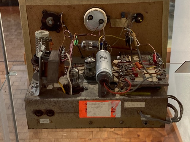
Grayson Evans KJ7UM (the author of Hollow State Design) was recently in Germany where he spotted this museum display of a homebrew receiver built in the GDR (the old East Germany) around 1983 by a 13 year-old. Very cool.
Here is today's task for SolderSmoke: Can you provide any more info on this receiver? The card indicates 0-V-1 which would be a regen with no RF amplifier, right? Maybe something like this:
Here's another great video from Helge LA6NCA. This is a follow-up to his Altoids Spy Transmitter project. Really well done. Hack-A-Day called this receiver "regenerative" so naturally I was disappointed, but when I watched I realized that it is NOT a regen but is instead a direct conversion receiver. TRGHS. All is right with the world. Thanks Helge! 73
Will's homebrew station is really something. The rig (it truly qualifies for this term of praise) is amazing all by itself (see below), but a look at Will's QRZ page reveals other ingenious inventions and techniques: There is the clock made from panel meters. And the method he uses for making aluminum project boxes. He even made an N0WVA regen receiver. That's the one I used in my ET-2. Fantastic.
Will really needs to share his homebrew skills with others. I hope he is soon in a local high school teaching students how to build things. Thanks Will!
Bill and Pete,
Just wanted to send a note to update you on the latest projects here. The last time I emailed, I mentioned wanting to build a superhet, which you (rightfully) discouraged, pushing for a DC receiver.
Well, I finished the superhet at the end of last year. I had most of the receiver working long before then, but got bogged down in an AGC system. The final receiver is a 5 band si5351a controlled single conversion superhet loosely based on Todd, VE7BPO's design with several modifications. I used a 9 Mhz IF instead of 4, I used a digitally controlled LO and BFO, and as mentioned, I added an AGC system, which ended up being the most challenging (and most interesting) part. The final AGC system I ended up with used the detector and amplifier side of Wes Hayward's "full hang" AGC from SSDRA, but I didn't have the IC IF amplifiers with variable gain, so instead, it fed a PIN diode attenuator circuit to control the IF gain. The final result worked great, but I nearly pulled my hair out getting it to work. I originally intended to build the receiver for 40 and 20 meters, but it ended up covering 80, 40, 30, 20, and 15 since I used the filter relay board from QRP Labs which had 5 slots.
After I got the receiver running, I decided I needed a matching transmitter, so I built up a simple CW transmitter to match. It uses an si5351a VFO driving a 74HC04 hex inverter as the buffer amplifier. The trick here is that by driving all the inverter gates in parallel, the output impedance is ~14 ohms broadband, suitable for driving a BJT PA without any need for matching transformers. The PA is 3 2N2222s in parallel with heat syncs putting out about 2 watts from 80 - 15.
The part I'm most proud of is that I have the arduino for the receiver connected to the arduino for the transmitter through a serial line. The receiver sends it's current frequency to the transmitter so that the transmitter can track the receiver's frequency as you tune (like a transceiver). I'll attach a few pictures of my homebrew station below. The transmitter is on the left, receiver is on the right. The box on top of the transmitter is my homebrew keyer. Next up on my build list is a solid state T/R switch.
Bill, I've enjoyed following the updates on the school DC receiver build. My local club is wanting to do some youth outreach, and I'd love to get them involved in building. I'm the only builder in the club though, so I don't know if I personally have the manpower to make it happen. Also, thanks for the recent info and pictures of Cuban homebrew rigs. I grew up listening to Arnie Corro, so I love seeing their resourcefulness and ingenuity. Makes me want to take apart some old electronics.
Pete, I'm enjoying following the 10M SSB project. With the uptick in propagation, I've been bitten by the 10M bug, and I'm thinking a 10M rig may have to be on my project list for this year.
Thanks to Peter Marks VK3TPM ("a bloke with too many hobbies") for alerting us to this magnificent homebrew receiver with the especially magnificent tuning dial.
We have used old CDs as dials for many years. I have one on my Q-31 Quarantine SW receiver. But never have we seen one with SolderSmoke emblazoned on it. FB OM.
Stephen VK2BLQ should make sure that those 6U8s haven't gone old on him. I recently replaced the 6U8s in my Mate for the Mighty Midget with 6EA8s. This seemed to rejuvenate the receiver.
Also, it is shame that Stephen doesn't keep that rig at 12 volts. 250 V? Yikes. As I often say, you CAN hurt yourself with 12 volts, but you really have to work at it. Not so with 250 V. One hand behind your back Stephen!
Farhan VU2ESE is largely responsible for this. He has recently been talking about VHF. (More about this in due course.). This started me thinking about my failed effort in London to get on 2 meter AM. My plan was to use the transmit portion of this HW-30 (above) with a 2-to-10 downconverter and my trusty Drake 2-B for receive.
Tony G4WIF also bears some responsibility: When I expressed interest in Farhan's VHF work, Tony sent me two articles from SPRAT. Both of them were about super-regenerative receivers.
Farhan's comments caused me to pull the HW-30 out of storage. I started poking around the transmitter. But then I noticed something: On receive, the AF amplifier was obviously working. Then, when I tuned through the 2 meter band, the rest of the receiver seemed to be working too. I fired up the HP-8640B sig gen on 2 meters and turned on the AM modulation. Indeed, the old receiver was inhaling!
This launched me into an effort to understand how super-regenerative receivers work. There are a lot of really weak explanations out there. You get the distinct impression that the person explaining the circuit does not understand it himself. This makes explaining it very difficult. I am not the only one to notice this phenomenon: Mike WU2D commented on this in one of his excellent super-regen videos. This one:
Mike very kindly said the operation of this circuit seems like "magic." I was thinking more in terms of Voodoo.
Howard Armstrong discovered super-regeneration years after he invented plain old regeneration. The new discovery came around 1921.
It looks like VHF guru Frank Jones had very early misgivings about super-regeneration. In his 1934 classic 5 Meter Radio Telephony, Jones seems unenthusiastic about the circuit and about our ability to understand it: "To explain, simply, exactly how this form of detection takes place is not a simple matter, but some of its characteristics are easy to visualize." In this book, Jones goes on to predict that super-regens will be superseded (!) by superhets. Indeed, in his 1961 book VHF for the Radio Amateur there are no super-regen circuits; all the receive systems are down-converters to HF receivers.
Still, with that HW-30 hissing away right next to me, I feel I need to understand how the super-regen works. I'm not there yet, but I'm trying. Here are some good resources:
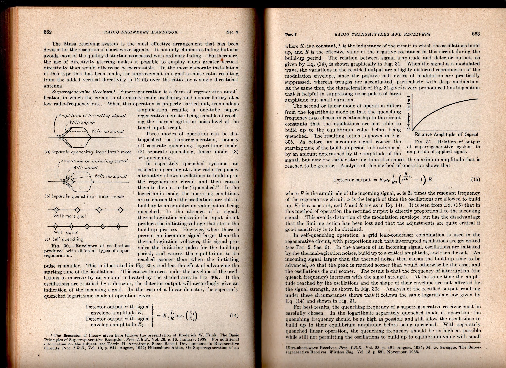
But the best so far (for me) is from Frederick Terman (one of the founders of Silicon Valley) in his 1943 classic Radio Engineer's Handbook. Click on the images for a clearer view.
I will definitely try to get the HW-30's 5 watt AM transmitter going. I am not so sure I'll do anything with the receiver. I think this is a matter of picking your battles and "finding joy." I didn't find joy in FT-8, so I stopped working with it. Same with my HA-600A, DX-40 Novice rig. Same with CW in general. And the same with SDR. I suspect that super-regen receivers may also fall into this category. I mean, let's face it, if you are not fond of ordinary regens, is there any real chance that you will like SUPER-regens? Even Frank Jones seems to have disliked them. And there is a reason Howard Armstrong moved on to superhets -- they are better! But still, that receiver is hissing away at me... Stay tuned.