Just go to http://soldersmoke.com. On that archive page, just click on the blue hyperlinks and your audio player should play that episode.
http://soldersmoke.com
When I first listened to Bob Crane's interview at FDIM with Keith Whites, I thought of the book "The Electronics of Radio" out of CalTech by David Rutledge. Keith Whites told me that the difference between his effort at University of Kentucky was that Rutledge's course was designed for freshmen at Cal Tech, while White's course was aimed at Juniors and Seniors.
I told Keith Whites that I had struggled to understand the Gilbert Cell and the NE602, the device that lies at the heart of the rig used in both courses: The NE-602 Gilbert Cell Mixer used in Wayne Burdick's NORCAL 40A. Here is how I came to understand the device: https://soldersmoke.blogspot.com/2021/11/how-to-understand-ne-602-and-gilbert.html
"Gilbert believes that childhood hardships—including at age three losing his father in World War II, leaving his mother and three other children penniless—force one to be resourceful. Before and during his teenage years, he had access to a plethora of inexpensive military surplus gear which greatly helped to make him inventive. Gilbert laments that today's aspiring engineers are lacking the visceral experience of handling and hefting large coils and tuning capacitors, transformers and vacuum tubes, and such. Today’s surplus circuit boards are all but useless as a source of inspiration, or even “spare parts” to tinker with."
Armed now with a NanoVNA, I took a look at the passband of the 5 MHz filter in my Barebones Superhet (BBRX) W4OP built it on a Circuit Board Specialist Board. He put a 5 MHz CW filter in there; I broadened the passband for phone by changing the values of the capacitors. Here is what the passband now looks like in the NanoVNA:
This is what DeMaw would call an "LSB filter." You would get much better opposite sideband rejection by using it with an LSB signal, placing the BFO/Carrier Oscillator slightly above the passband, in this case near 5.002 MHz.
When I first built the down converter to get the 18.150 MHz signal down to the 7 MHz range (where I had the receiver running) I used an 11 MHz crystal for the NE602's local oscillator. But this created a big problem: 18.150 - 11 = 7.150 MHz. That is in the 40 meter band, but note: NO SIDEBAND INVERSION. Then in the BBRX 7.150 MHz - 2.150 MHz = 5 MHz (the filter frequency) but again: NO SIDEBAND INVERSION. The signal started as a USB signal and remained a USB signal.
I briefly tried shifting the BFO frequency to the other side of the filter passband. If I could get it to around 4.985 MHz, it might work, but because the filter passband was so large, and because the crystal frequency was so low, I was unable to shift the crystal frequency that far. In any case the results would have been less than ideal because of the "LSB" shape of the filter. Back to the drawing board.
I decided to cause one sideband inversion.
At first I put a 25.175 MHz crystal module in my down converter. This shifted the 17 meter phone band down to the 40 meter CW band. It worked, but I cold hear strong 40 meter CW signals being picked up by the wiring of the receiver (the box is plastic!). I went back to the module jar in search of frequency that would move 17 meter phone to the 40 meter area (so I would not have to re-build the BBRX front end) but outside the actual 40 meter band.
I ended up using a 25 MHz crystal in the down converter. 25 MHz - 18.150 MHz = 6.85 MHz WITH SIDEBAND INVERSION. After checking on the NA5B Web SDR to see that there are no strong signals in the 6.835 to 6.89 MHz range, I retuned the output circuit on the converter and tweaked the input capacitor on the Barebones. I shifted the VFO frequency down to 1.835 to 1.89 MHz and put the BFO at 5.002 MHz. The receiver was inhaling on 17 meter SSB.
One more change to the BBRX: in his June 1982 QST article, DeMaw warned that trying to get speaker level audio out of the 741 op amp that he used would result in audio distortion. And it did. So I put one of those little LM386 boards I have been using into the BBRX box. I just ran audio in from the wiper of the AF gain pot. It sounds good.
In effect this is my first double-conversion receiver. I usually prefer single conversion, but this project has highlighted for me one of the advantages of double conversion for someone like me who eschews digital VFOs: Starting with a crystal filter at 5 MHz, with double conversion I could keep the frequency of the LC VFO low enough to ensure frequency stability. That would have been impossible with a 5 MHz IF in a single conversion 17 meter rig. But if I were starting from scratch for a 17 meter rig, I could stick with single conversion by building the filter at 20 MHz, keeping the VFO in the manageable 2 MHz range.
Now, on to the SSB transmitter. The Swan 240 dual crystal lattice filter from the early 1960s needs some impedance matching.
I think the key to understanding the Gilbert Cell Double Balanced mixer is to separate out the three tasks that this device completes, and consider them one at a time, using different diagrams:
1) It mixes two signals to produce sum and difference outputs.
2) It balances out the RF input.
3) It balances out the LO input.
Task 1 -- Mixing
The Gilbert cell is like the diode ring mixer in that it switches the polarity of the input signal at a rate set by the Local Oscillator. Another way of saying this is that the mixer multiplies the input signal by 1 and by -1.
Steve Long of the University of California described the essence of this mixing this way (using the diagram above):
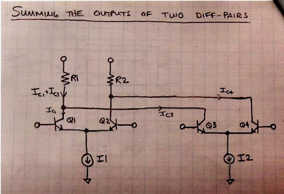
In an effort to see this for myself, I drew (noodled!) this diagram:
There are four transistors -- two differential pairs with RF coming into the bases of the pairs.
The LO is a square wave. The LO alternately turns on transistors 1 and 4, then 2 and 3. When 1 and 4 are on, we are in period 1 -- here there is no switching of polarity. Portions of the RF waveform are passed to the outputs. But when the LO turns on transistors 2 and 3, portions of the RF wave form are "crossed over" to the opposite output. Polarity is reversed. We see this in period number 2.
Take a look at the resulting output waveforms. This is the same waveform we see coming out of a diode ring mixer. I really like this drawing because in that complex waveform you can actually see the sum and difference frequencies:
I could see this diode ring waveform myself on my oscilloscope:
In a diode ring, and in other diode mixers, the balancing out of the input signals really takes place in the trifilar toroidal coils that are part of the circuit. Barrie Gilbert needed an integrated circuit mixer that did not use coils.
Again referring to the above diagram, Steve Long of the University of California put it this way:
The ideal balanced structure above cancels any output at the RF input
frequency since it will average to zero.
To fully understand this I find it helps to look at the Gilbert cell circuit drawn in a different way. Here is a drawing from Alan Wolke W2AEW that I found very helpful. It comes from his excellent YouTube video: https://www.youtube.com/watch?v=7nmmb0pqTU0
Suppose the RF waveform at I1 is causing the current through R1 and R2 to increase. At the same time, the opposite phase current through I2 will be causing the current through R1 and R2 to DECREASE. So there is no net effect of the RF signal at the output. The RF is balanced out.
TASK 3 - Balancing Out the Local Oscillator Signal
Here too I used my own drawing, and was guided by the words of Steve Long:
It also cancels out any LO frequency
component since we are taking the IF output as a differential signal and the LO
shows up as common mode.
The important thing to realize here is which transistors are being turned on and off by the local oscillator signal. On one half cycle of the LO, transistors 1 and 4 are on. So the LO signal at the LO frequency are both pulling the same amount of LO frequency current through the resistors. So you have the same change in voltage at the output terminals. And the output terminals are differential. The LO signal results in no voltage difference between the terminals. So the LO frequency is balanced out.
The same thing happens on the following half of the LO cycle. Here, transistors 2 and 3 are turned on. Again, both transistors pull the same amount of LO frequency current through the resistors. There is no differential voltage. So no LO frequency energy passes to the output. LO frequency is balanced out.
--------------------------------
I am surrounded by Gilbert Cell Mixers and I have been using them in my homebrew rigs for many years. I use them in up-converters for my RTL-SDR receivers. I have one in the downconverter for my 17 meter receiver and had one as the mixer in my first SSB transmitter. I built a 40 meter SSB transceiver with NE602s on either end of the crystal filter. Years ago, I built a DSB transceiver with several NE602s. My SST QRP CW transceiver is made with NE602s. I have on my bookshelf Rutledge's book "The Electronics of Radio" that is all about the NORCAL 40 transceiver, built using NE602 chips. But until now I really didn't know how these chips worked. Truth be told, for me they were mysterious little black boxes, and that bothered me. Now I feel a lot better about using these clever devices. I plan on stocking up on the old style (non-SMD) NE602s.
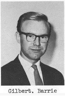
Apparently Barrie Gilbert rejected the idea that he invented the circuit that bears his name. It seems that Howard Jones first used this circuit in 1963, with Gilbert developing it independently (in an improved form) in 1967.
Barrie Gilbert was quite a guy, with electronic roots in the world of tinkering:
"SolderSmoke -- Global Adventures in Wireless Electronics" is now available as an e-book for Amazon's Kindle.
Here's the site:
http://www.amazon.com/dp/B004V9FIVW
Bill's OTHER Book (Warning: Not About Radio)
Click on the image to learn more
Where are the readers of SolderSmoke Daily News?
Pete Juliano N6QW
SolderSmoke Co-Host and Master Homebrewer
Dean Souleles KK4DAS
With beret and with a Michigan Mighty Mite in hand
Re: Receiver Mica Disease
-
You might be seeing the effects of bad silver-mica capacitors. Apparently
silver can migrate thru the mica insulation forming little fingers
(dendrites) wh...
December 20, 2024. A Case for Zuppe Inglese
-
With Christmas but 5 days away, my thoughts have turned to homebrewing
special dishes traditionally served only at this time of year. Speaking of
tradition...
Bryce and Joe’s Triple-State POTA Activation
-
A Triple-State POTA activation! by Bryce Bookwalter (KD9YEY) and Joe Ladwig
(W9NVY) It’s finally winter here in Southern Indiana, which, for many,
brings a...
Tech news spot on ABC Radio
-
Nightlife Tech Guru Peter Marks, a software developer and technology
commentator from Access Informatics, joined Philip Clark on Nightlife to
discuss the l...
HRWB 225 - QRP Radio Design with Jonathan KM4CFT
-
In this episode we meet Jonathan Kayne, KM4CFT, the designer of a very
popular new QRP radio called the CFT-1. Jonathan shares his journey from
concept ...
QRP HomeBuilder rebrands to Popcorn Electronics
-
Greetings Friends! Well, it's time to re-imagine QRP HomeBuilder. I'm
going back to the beginning and rebranding as Popcorn Electronics. This was
the si...
The George Batterson 1935 QSO Party
-
*VE3AWA - TPTG 210s*
After the most recent running of the *AWA’s Bruce Kelley 1929 QSO Party*, a
group of dedicated ‘29 enthusiasts and builders were hopi...
The November - December 2024 SARC Communicator
-
*Another BIG issue*
The final issue of the year. The November-December Communicator, digital
periodical of Surrey Amateur Radio Communications is now avail...
Hollow-State Design, 3rd Edition
-
Hollow-State Design, 3rd Edition is available from: Lulu Press:
tinyurl.com/hollowstatedesign3 eBay: search for “hollow-state design”
Electric Radio bookst...
I Finally Bought My Dream Airplane
-
Aviation has been a love of mine since I was a very little person. Living
in Nevada, seeing posters and ads for the Reno Air Races, specifically the
Texa...
2000 47pF Caps ...
-
An unexpectged package arrive in the mail today. Did you ever wonder what
2000 47pF NP0 capacitors look like? Thanks to John, AB2XT I will never run ...
New QRP Cluster From OM0ET and OM6APN
-
By DX EXPLORER
DX EXPLORER
Paul OM0ET and Peter OM6APN recently launched a new cluster dedicated to
QRP operations. Have a look and I hope you will enjoy...
Daylight Again – An all Analog Radio
-
What’s all this? In 10 seconds, A high performance, 7MHz, 5 watt SSB rig
Draws just 24 mA of current 90 dB dynamic range, 80 dB close-in dynamic
range 3D ...
Digi-chirp! Digital synthesis of ‘nostalgic’ CW
-
The bottom ends of 80, 40 and 20m are not what they used to be. For
starters, the busiest part is the digital segment where computers talk to
computers – l...
SMA Torque Wrench for the NanoVNA (uncalibrated)
-
I have been using SMA connectors on most of my projects, and have
occasionaly gotten a slightly different reading than I had expected. Using
the NanoVNA, ...
40m SSB Tramping Rig
-
Please see my YouTube channel for details of the build.
http://www.youtube.com/c/CharlieMorrisZL2CTM
*2N3904 Antenna Amplifier (initial)*
Voltage gain is ...
Modifications to the Dayton/FDIM-2019 Antuino
-
The Dayton Antuino has sub-optimal performance. This is a short note on
improving it to an 80 db range of measurements. The trouble with Antuino
2.0 (the o...
Raduino as NBFM TX
-
Here is a neat, 30 minute hack for your Raduino to turn the Si5351 into a
pretty stable, solid NBFM transmitter. The hack is to add a varactor diode
in ...
QRP Labs shop!
-
[image: Shop]
All QRP Labs kits may be ordered online securely at the shop, with PayPal
payment.
*Click here to visit the shop!*
*Click!*
*Shop! Order...