

I think the key to understanding the Gilbert Cell Double Balanced mixer is to separate out the three tasks that this device completes, and consider them one at a time, using different diagrams:
1) It mixes two signals to produce sum and difference outputs.
2) It balances out the RF input.
3) It balances out the LO input.
Task 1 -- Mixing

The Gilbert cell is like the diode ring mixer in that it switches the polarity of the input signal at a rate set by the Local Oscillator. Another way of saying this is that the mixer multiplies the input signal by 1 and by -1.
Steve Long of the University of California described the essence of this mixing this way (using the diagram above):
An ideal double balanced mixer simply consists of a switch driven by the local
oscillator that reverses the polarity of the RF input at the LO frequency. http://literature.cdn.keysight.com/litweb/pdf/5989-9103EN.pdf
In an effort to see this for myself, I drew (noodled!) this diagram:

There are four transistors -- two differential pairs with RF coming into the bases of the pairs.
The LO is a square wave. The LO alternately turns on transistors 1 and 4, then 2 and 3. When 1 and 4 are on, we are in period 1 -- here there is no switching of polarity. Portions of the RF waveform are passed to the outputs. But when the LO turns on transistors 2 and 3, portions of the RF wave form are "crossed over" to the opposite output. Polarity is reversed. We see this in period number 2.
Take a look at the resulting output waveforms. This is the same waveform we see coming out of a diode ring mixer. I really like this drawing because in that complex waveform you can actually see the sum and difference frequencies:

I could see this diode ring waveform myself on my oscilloscope:
TASK 2 -- Balancing Out the RF Input
In a diode ring, and in other diode mixers, the balancing out of the input signals really takes place in the trifilar toroidal coils that are part of the circuit. Barrie Gilbert needed an integrated circuit mixer that did not use coils.

Again referring to the above diagram, Steve Long of the University of California put it this way:
The ideal balanced structure above cancels any output at the RF input
frequency since it will average to zero.
To fully understand this I find it helps to look at the Gilbert cell circuit drawn in a different way. Here is a drawing from Alan Wolke W2AEW that I found very helpful. It comes from his excellent YouTube video: https://www.youtube.com/watch?v=7nmmb0pqTU0
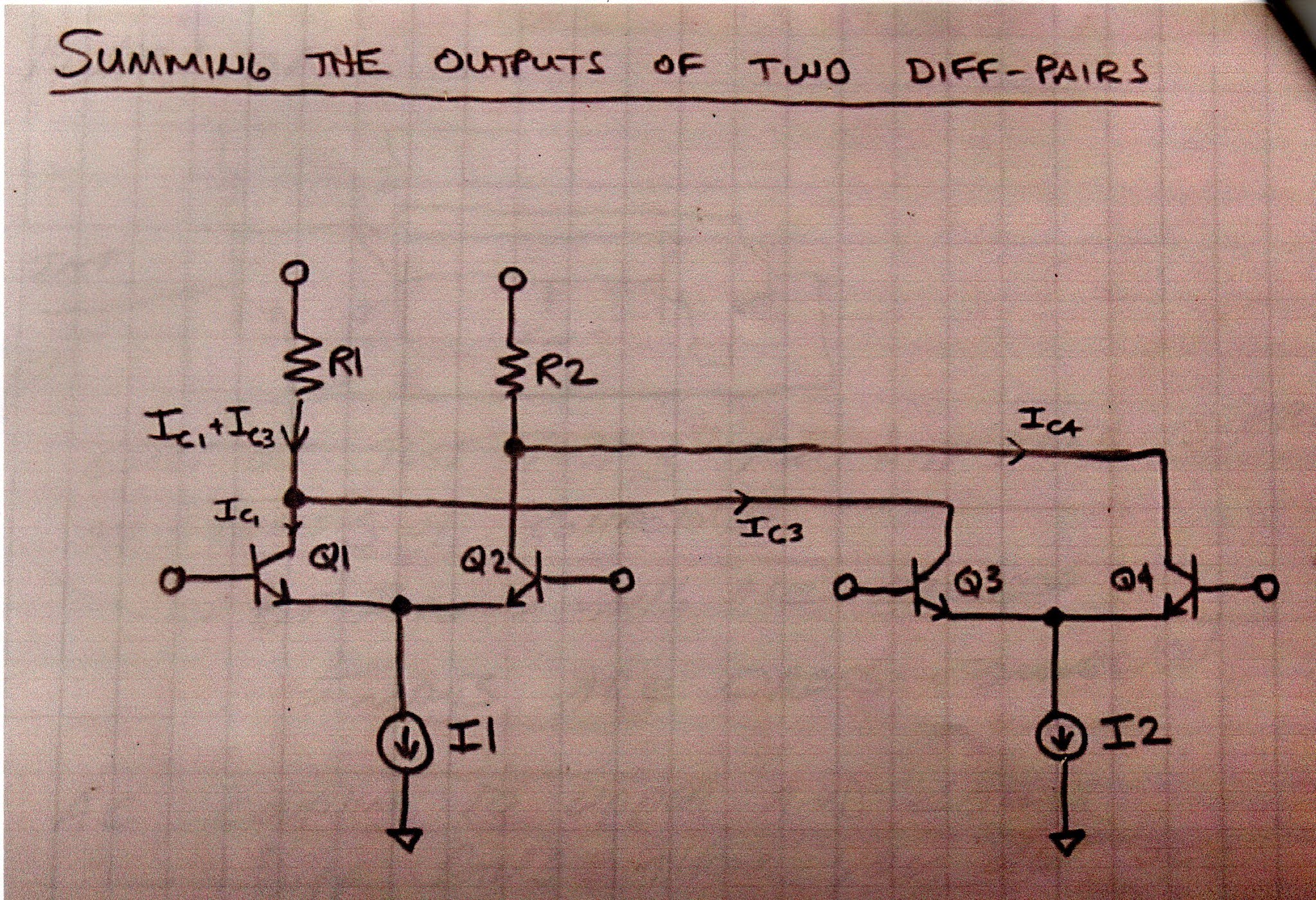
Suppose the RF waveform at I1 is causing the current through R1 and R2 to increase. At the same time, the opposite phase current through I2 will be causing the current through R1 and R2 to DECREASE. So there is no net effect of the RF signal at the output. The RF is balanced out.
TASK 3 - Balancing Out the Local Oscillator Signal

Here too I used my own drawing, and was guided by the words of Steve Long:
It also cancels out any LO frequency
component since we are taking the IF output as a differential signal and the LO
shows up as common mode.
The important thing to realize here is which transistors are being turned on and off by the local oscillator signal. On one half cycle of the LO, transistors 1 and 4 are on. So the LO signal at the LO frequency are both pulling the same amount of LO frequency current through the resistors. So you have the same change in voltage at the output terminals. And the output terminals are differential. The LO signal results in no voltage difference between the terminals. So the LO frequency is balanced out.
The same thing happens on the following half of the LO cycle. Here, transistors 2 and 3 are turned on. Again, both transistors pull the same amount of LO frequency current through the resistors. There is no differential voltage. So no LO frequency energy passes to the output. LO frequency is balanced out.
--------------------------------
I am surrounded by Gilbert Cell Mixers and I have been using them in my homebrew rigs for many years. I use them in up-converters for my RTL-SDR receivers. I have one in the downconverter for my 17 meter receiver and had one as the mixer in my first SSB transmitter. I built a 40 meter SSB transceiver with NE602s on either end of the crystal filter. Years ago, I built a DSB transceiver with several NE602s. My SST QRP CW transceiver is made with NE602s. I have on my bookshelf Rutledge's book "The Electronics of Radio" that is all about the NORCAL 40 transceiver, built using NE602 chips. But until now I really didn't know how these chips worked. Truth be told, for me they were mysterious little black boxes, and that bothered me. Now I feel a lot better about using these clever devices. I plan on stocking up on the old style (non-SMD) NE602s.
Apparently Barrie Gilbert rejected the idea that he invented the circuit that bears his name. It seems that Howard Jones first used this circuit in 1963, with Gilbert developing it independently (in an improved form) in 1967.
Barrie Gilbert was quite a guy, with electronic roots in the world of tinkering:

My colleague and friend Barrie was the first to say that the mixer is NOT a Gilbert Cell Mixer. He first described the 4-quadrant analog multiplier in the 1968 International Solid State Circuits Conference (ISSC).
ReplyDeleteVery curious timing - just yesterday I was considering a receiver design with the 602 and this morning your post pops up. Consequently, I ordered a supply of SA602's and while doing that found a fascinating bit of history on this part: http://www.ur5ffr.com/viewtopic.php?f=18&t=166
ReplyDeleteBob: Yea that NA5N post was used as one of the earliest posts on the SolderSmoke blog (2009)
ReplyDeletehttps://soldersmoke.blogspot.com/2009/06/na5n-on-ne602.html
And we used it even earlier (December 2006) on the Gadgeteer website. Thanks, 73 Bill
I also appreciated your explanation in your book... in fact, all of the explanations in that book are a great way to view things usually taught with a lot math in university EE courses. Your intuitive approach puts it in perspective.
DeleteBill -
ReplyDeleteThanks for the post, will take me a while to really read and understand !
On Saturday I received the Dec. 2021 QST and in addition to the page on Bill Meara there was a review of the new TR-25 QRP rig by WA3RNC.
If you search the QST archives for WA3RNC you will find John's Feb. 1988 article: The Neophyte Receiver.
I believe WA3RNC was the first to publish a 2 chip receiver design using the LM386 and the NE602 - the direct conversion design that launched a zillion kits :)
And yes, the TR-25 uses the SA612 and the LM386 although now in a superhet configuration.
Excellent article! KD1JV has used the 74HC4053 as a mixer (his DCxx series) and it works VERY well. Would like to see some numbers on it compared to a ne602. It is suppose to be immune to BC overload.
ReplyDeleteFYI the 74HC4053 is a High-Speed CMOS Logic Analog Multiplexers. Basically a 3-channel analog switch (SPDT).
Delete