Podcasting since 2005! Listen to Latest SolderSmoke

Showing posts with label Fishpool -- Tony. Show all posts

Tuesday, March 7, 2023

SolderSmoke Podcast #244 PETE IS BACK! TR-7, CK722, BFR106, HP8640B, High-School Receiver, 10 Min TX, MAILBAG


SolderSmoke Podcast #244 Is available:

http://soldersmoke.com/soldersmoke244.mp3

Video version at:

(118) SolderSmoke - YouTube

HE’S BACK! HOORAY! PETE JULIANO N6QW IS BACK! SOLDERSMOKE COMMUNITY WAS SENT INTO A COLLECTIVE FUNK BY PETE’S ABSENCE. ---------------- Pete’s TR-7 (SEE VIDEO ABOVE) CK722 The BFR106
Pete's new blog: https://hamradiogenius.blogspot.com/ ---- Update on the high school project: Mixers made. Harder than they seemed. First QSO with the DC RX. Allan W4AMV Homebrewer TRGHS Ten Minute Transmitter – Better than the MMM! AF4K (SK) crystals. Other supporting projects: Farhan in Hyderabad. Rick N3FJZ, Walter KA4KXX, Andreas DL1AJG Electronics for Biologists. Peter Marks VK3TPM (fighting the siren call of the Si5351) . Steven VK2BLQ built a beautiful one. Daniel VE5DLD will build three of them with his students. Orlando PY2ANE is building one in Brazil. This week: The Bandpass Filter. (Thank you Hans Summers) --- SHAMELESS COMMERCE DIVISION: BECOME A PATRON VIA PATREON. I am posting some fun stuff for the Patrons. AMAZON SHOPPING ADS Now on both the left and right columns. CHECK OUT Mostly DIY RF in the right hand column. ---- My HP8640B Lives to Fight another day. Two new DMMs A low-end Fluke and a AstroAI 6000 Electrolytic Replacement Controversy Continues
Mailbag: -- Dave AA7EE is blogging again! Yea! -- Mike Rainey AA1TJ back in the Hobbit Hole Building a WWVB receiver. -- Farhan is coming to FDIM. -- Tony G4WIF reminds us that 39 bucks for JUST a 60 MHz counter would be great! -- Dave VE3EAC again helped me fix my HP8640B. -- Dean KK4DAS finalizing 10 meter DSB rig. FB. Upgraded my NanoVNA. -- Mike KD4MM giving me a Nano VNA for the SolderSmoke Shack South. -- Ian VK3LA asked what happened to Chuck Adams content. Good question. -- Don ND6T and I have been discussing envelope detection. -- Nick M0NTV working on AM modulators. He has a new video. -- Ciprian YO6DXE built a Ten Minute Transmitter. -- Steve EI5DD Connacht Regional News: https://www.docdroid.net/YJAV800/crnews0223-pdf

Hyderabad DC RX Workshop

Farhan explaining the receiver in Hyderabad

Sunday, September 11, 2022

An Especially Good (Old) SolderSmoke Podcast


February 22, 2008    
-- We were in Rome.  
-- I read a 1931 QST ad sent to me by my fellow "Hambassador" David Cowhig, WA1LBP; David was in Okinawa when he sent it. 
-- I describe Wes Hayward's comments about Pat Hawker, G3VA. 
-- I talk about getting on the air with my HW-8 (after fixing it!), re-tubing my Drake 2-B, and putting up a 30AWG antenna in Rome. 
-- I describe meeting up with Roman hams (including amplifier manufacturer I0ZY!) and visiting the local radio club.
-- The Science Museum in Florence, Italy. 
-- DSB from Rome with my NE602 rig. 
-- Tony Fishpool and Graham Firth's Test Gear book. 
-- An important corollary to Murphy's Law. 
-- Listening to SolderSmoke from safari, under the Southern Cross in South Africa. 
-- Ron Sparks calls in from Dubai. 

You can put on a playlist of all the SolderSmoke podcasts here: 

Saturday, March 26, 2022

Getting More Rigorous About Receiver Design (Video)


As I finished up the receiver on my 17-12 SSB transceiver, I started to wonder -- how good is it?  
Sure, I could hear stations on both bands, and when I got started as a homebrewer that was enough for me. But now, I find myself wondering about receiver performance.  Did I get the gain distribution right?  Do I have too much gain ahead of the mixer?  Ahead of the crystal filter?  Is the receiver generating too much noise?  Can I hear the band noise?  If not, why not?  Do my circuits lose linearity in the presence of strong signals?  What is my dynamic range?

This is a big complicated subject that takes time to master.  

I am just beginning.  I found the video above to be very helpful. 

I was jealous of this fellow's audio spectrum analyzer, but then Tony G4WIF told me that the the analyzer that this fellow was using was really just a sound card and some software.  I quickly found a similar piece of free software that lets me do the same thing he did:  Look at the audio output of my receiver and watch what happens as I put an RF signal of varying levels into the antenna port.  

I am using Visual Analyzer, a free program out of Italy: 

https://www.sillanumsoft.org/   

 The author of the software seems very cool" 

My name is Alfredo Accattatis; I love electronics and software, and I have been working for years in commercial companies as software/firmware engineer and software designer. I've been writing programs for embedded systems (with DSP and MICROCONTROLLERS), for PC, for Avionic Computers and even for Mainframes, using C, C++, Pascal, Ada, REXX and assembly. I starting write VA during my free time just for fun and using (also) my DSP experience. The program was and is completely FREE.

More info about Alfredo here: 

https://www.sillanumsoft.org/about_the_author.htm

Do you folks think I need to buy the kind of True RMS Audio Voltmeter that is being used at the end of the above video? 

Friday, November 5, 2021

The Importance of Keeping the Noise FLAT


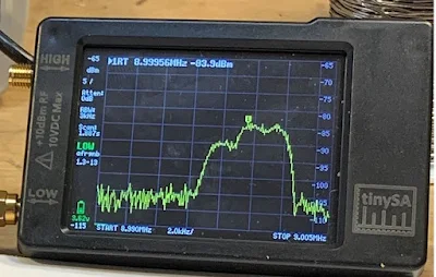
A few days ago I put up a blog post about using a noise generator (in my case my cheap FeelTech sig generator) and my TinySA spectrum analyzer to look at the passband of a crystal filter.  I was using the 9 MHz filter used by Dean KK4DAS and the Vienna Wireless Makers Group.  The idea is simple: insert broadband noise into the input. The filter should pass more of the noise that falls within its passband.  The TinySA should let you see this.  At first, I was pleased that I could clearly see the passband.   I thought I had succeeded.  See above. 

But I was bothered by something.  Look at that bump in the passband.  It should be close to flat across the top.  

I decided to take a look at the same filter with my NanoVNA.  Here I was not using a noise generator.  The NanoVNA sweeps the filter using and looks at output in the Log-Mag mode.  Here is what it looked like (below): 


That was much better.  But why the difference?   Tony Fishpool G4WIF suggested that my noise source might not be putting out noise at the same level on all frequencies.  I took at look at the noise output of the FeelTech sig gen in the range of the filter passband (with some above and below frequencies for reference) and I found that the flatness of this noise depended a lot on what frequency I had the sig gen set to.  I tuned it around a bit until I found a setting that produced a flat noise output in the desired frequency range.  Then I went back and swept the filter with the noise and the TinySA again.  Here is what it looked like with the "flat" noise: 


Better,  I think.  Closer to the passband displayed by the NanoVNA.   

Tony points out that these Chinese sig gens don't really put out random noise -- they give us predictable noise.  Dean said "Predictable Noise" would be a good name for a rock group.   I said they could open for my favorite: "The Ceramic Spurs." 

Saturday, October 30, 2021

Using Noise to Sweep a Filter with the TinySA

 
I've been meaning to try this for a long time.  Years ago Tony Fishpool and Graham Firth wrote about using a noise generator and a spectrum analyzer to sweep the bandpass of a filter. The idea here is to send very broadband noise into a filter, and then use a spectrum analyzer to see which frequencies make it through.   

I thought about building a noise generator like the one in Tony and Graham's book, but then it occurred to me that probably had one sitting on my bench.  Sure enough, a look at the manual for my cheap FeelTech function generator revealed that PRESETS 3 and 8 are noise generators.   I quickly pulled out a 9 MHz filter that Dean KK4DAS had given me, put the noise into one end and the TinySA on the other end.  Bob was quickly my uncle.  See above.  

More recently Tony G4WIF built a comb generator as a noise source: 

Thanks to Tony, Graham, and Dean.  And to the folks who developed the TinySA. 

Wednesday, October 20, 2021

Super-Regeneration is Super-Strange


Farhan VU2ESE is largely responsible for this.  He has recently been talking about VHF.  (More about this in due course.).  This started me thinking about my failed effort in London to get on 2 meter AM.   My plan was to use the transmit portion of this HW-30 (above) with a 2-to-10 downconverter and my trusty Drake 2-B for receive.  

Tony G4WIF also bears some responsibility:  When I expressed interest in Farhan's VHF work, Tony sent me two articles from SPRAT.  Both of them were about super-regenerative receivers.  

Farhan's comments caused me to pull the HW-30 out of storage.  I started poking around the transmitter.  But then I noticed something:  On receive, the AF amplifier was obviously working.  Then, when I tuned through the 2 meter band, the rest of the receiver seemed to be working too.  I fired up the HP-8640B sig gen on 2 meters and turned on the AM modulation.  Indeed, the old receiver was inhaling!  

This launched me into an effort to understand how super-regenerative receivers work.  There are a lot of really weak explanations out there. You get the distinct impression that the person explaining the circuit does not understand it himself.  This makes explaining it very difficult.  I am not the only one to notice this phenomenon:  Mike WU2D commented on this in one of his excellent super-regen videos.  This one:  


Mike very kindly said the operation of this circuit seems like "magic."  I was thinking more in terms of Voodoo.  

Howard Armstrong discovered super-regeneration years after he invented plain old regeneration.  The new discovery came around 1921.

It looks like VHF guru Frank Jones had very early misgivings about super-regeneration.  In his 1934 classic 5 Meter Radio Telephony, Jones seems unenthusiastic about the circuit and about our ability to understand it:  "To explain, simply, exactly how this form of detection takes place is not a simple matter, but some of its characteristics are easy to visualize."  In this book, Jones goes on to predict that super-regens will be superseded (!) by superhets.  Indeed, in his 1961 book VHF for the Radio Amateur there are no super-regen circuits; all the receive systems are down-converters to HF receivers. 

Still, with that HW-30 hissing away right next to me, I feel I need to understand how the super-regen works.  I'm not there yet, but I'm trying.  Here are some good resources: 

A good article from Wireless World 1946:  

A student's write up of his effort to understand: 

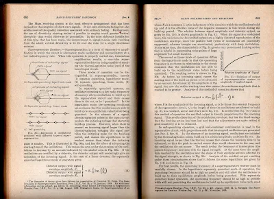
But the best so far (for me) is from Frederick Terman (one of the founders of Silicon Valley) in  his 1943 classic Radio Engineer's Handbook.  Click on the images for a clearer view. 


I will definitely try to get the HW-30's 5 watt AM transmitter going.  I am not so sure I'll do anything with the receiver.  I think this is a matter of picking your battles and "finding joy."   I didn't find joy in FT-8, so I stopped working with it.  Same with my HA-600A, DX-40 Novice rig.  Same with CW in general.  And the same with SDR.  I suspect that super-regen receivers may also fall into this category.  I mean, let's face it, if you are not fond of ordinary regens, is there any real chance that you will like SUPER-regens?  Even Frank Jones seems to have disliked them.  And there is a reason Howard Armstrong moved on to superhets -- they are better! But still, that receiver is hissing away at me...  Stay tuned. 

Saturday, July 3, 2021

M0NTV's Latest Breadbox Rig -- The Radio Gods Have Spoken (TRGHS)!


Tony G4WIF sent me this video from Nick M0NTV.  It presents Nick's latest Bread Bin project -- "The Optimizer." 

-- I really like the Bread Box enclosures.  And leaving the b and the d on the box is just brilliant.  These letters now stand for BiDirectional!  They even appear symmetrical.  TRGHS!

-- The switch for a tuning tone is a great idea.  I still have to plug my Maplin AF sig gen into the mic jack to do this.  FB. 

-- I too have the connector on the back for keying the outboard linear amplifier.  (Shhh! Don't tell G-QRP!) 

-- As for the bidirectional TIA amps.  I'm really glad that someone else is using these circuits.  Wes's article came out in 2009 and concluded with a call for someone to build a complete rig with these circuits.  I wonder how many rigs like this have been made.  It is a great circuit.   One thing I would suggest for Nick:  Wes's article points out that you CAN have higher gain in one direction than you have in the other.  Just use resistor values in the chart provided in the 2009 article.  You could have an amp with 15 db in the transmit direction and 24 db in the receive direction.  BTW:  I have been getting a lot of help from Alan W2AEW and Farhan VU2ESE on how to use the NanoVNA to confirm the input and output impedances on solid state amplifiers. 

-- For many years I had the same map of the Moon in my shack.  I hope that map makes it to the new house Nick. 

-- Finally, I was really surprised to hear EI0CL calling CQ during Nick's demo of the receiver.  That is Michael Higgins out in Galway.   Michael was one of my regular contacts when I was out in the Azores.  He is a truly amazing guy.  He is mentioned frequently in my "SolderSmoke -- Global Adventures in Wireless Electronics" book.  TRGHS. 

Friday, March 12, 2021

The Secret Life of LEDs -- A new Tim Hunkins Video


Thanks to Tony G4WIF for alerting us to this really nice video from the fellow who made all those great "Secret Life of Machines" videos.   This video on LED's makes me want to improve the lighting in my work shop.  And I think I need some more high wattage resistors.   I'm really glad Tim Hunkins is making more videos.  His look at the Secret Life of  Radio was a real masterpiece. 

Sunday, January 31, 2021

Repairing My Maplin Audio Waveform Generator

I picked this generator at the Kempton Park rally in London many years ago.  I use it quite a bit, not only for circuit testing but also as an easy way to get my homebrew BITX rigs to send a signal so that I can adjust my antenna.  I just plug this thing into the mic jack, crank in a small amount of 1 kHz audio, and I am ready to minimize SWR. 

It never gave me any real problems until last week.  I opened it up and examined the circuitry for the first time.  Lots of mystery chips in there. Fortunately they are all socketed.  Thank you Maplin. 

Even without really knowing how each of the ICs work, it was easy to troubleshoot. See the schematic in the article that begins on page 21 in this .pdf: 

My Rigol scope showed a good signal going into and coming out of IC8, the LF351 op-amp.  From there the signal goes to IC5 a 4066BE.  But nothing was coming out of IC5.  Thus IC5 was my lead suspect.  I put in a quick order to Digikey.  A couple of days and a few bucks later the chips (as always, I ordered several) were on my doorstep.  Within a few minutes IC5 was replaced and the generator was as good as new. 

One annoying problem with this generator is that it has no automatic shut-off circuitry.  So if I forget to turn it off, I soon have to buy two 9V batteries. Tony G4WIF suggested a simple timer circuit.  I may do that soon.  Or, given that we are already on the IC dark side with this project, there is this: https://www.youtube.com/watch?v=C4C2H_3BU3o&feature=youtu.be 

I recently find myself replacing a lot of chips in various rigs and devices in my shack.  It seems that chips go bad more frequently than discrete transistors or even tubes.  But maybe I'm just using older gear with older, more fragile chips.   What do you folks think? 

Thursday, September 24, 2020

Global Specialties Corporation 6000 Frequency Counter -- Anyone have a Plessey SP8630B Chip?


Continuing my effort to improve my workbench and its test gear, this week I turned to an old frequency counter that I picked up at the Kempton Park Radio Rally in London many years ago. It was not working when I got it, but long-time SolderSmoke listeners will recall the tale of woe that resulted from my having soldered a replacement IC (that Tony Fishpool G4WIF had sent me) UPSIDE down.  Tough times my friends,  tough times. 

Well,  I'm working on it again.  First I converted it from 220 to 110 power.  I had a transformer in the junk box that fit nicely, both electrically and mechanically.  In the course of doing this, I learned something about this counter that I did not know:   As long as it is plugged in, even if you turn it off, the time-base oscillator keeps running.  And get this Color Burst Liberation Army members:  The oscillator runs at 3.579545 MHz.  TRGHS.    

With sunspots scarce and with Pete pessimistic about the solar cycle, VHF and UHF now seem more interesting.  I need to have more test gear for the higher frequencies.  This counter works up to 650 MHz.  Yea! 

When I first fixed this thing, I was quite pleased to get it going with "Input A -- 5 Hz to 100 MHz."  But now I want to get "Input B -- 40 MHz to 650 MHz" working also. I used a 50 MHz signal from my newly repaired HP-8640B to trouble shoot Input B.  I think one of the divider chips is bad.  It is a Plessey SP 8630B.   Does anyone have one of these chips in their junk box?  


Friday, June 12, 2020

Software for Computer Interface with NanoVNA: NanoVNASaver


In the UK, "brilliant" is high praise indeed.  So when Tony G4WIF told me that the NanoVNASaver software was brilliant, I took heed. 

Being able to use the tiny (nano!) device with your computer makes it a much more accessible and useful tool, especially for those of us with fat-finger syndrome. 

The photo above shows the NanoVNA measuring Return Loss and SWR  on my 40 meter dipole. You can see the identical Smith Chart traces on the two screens. 

Download and installation was very easy. I got my Windows PC version from here: 

Other versions available from here: 

Coincidently, a fellow just today put out a video on how to use this software with the NanoVNA. 

Thanks Tony! 

Wednesday, May 27, 2020

Antennas, Money, and Ham Psychology


During SolderSmoke Podcast #222, Pete lamented the fact that many hams are willing to spend significant amounts of money on "manufactured" dipole antennas that are little more than pieces of wire.  Tony Fishpool G4WIF sent a graphic on the wire antenna he uses (see above).  He also shared an anecdote about G5RV antennas and G-QRP Club founder George Dobbs:  

From Tony: 

The aerial that I’ve had so much fun with, an End Fed Half Wave, cost me £8 ($9.80) for the toroid and the rest came from the junk box. The reel of wire was probably a £1  ($1.25) from a radio rally. You never pay big money for wire at a rally. People take it there to get rid of
it!

It covers 80m and all  harmonically related bands.
My garden is too small so I cheated by using some linear loading to
make it fit. (on the back fence).

WIth 5 watts CW on 40m I can hit the USA reverse beacons most mornings.

It was about £9 ($11) to make - but if you count the Spiderbeam

12m pole, it  was another £98 ($120).

I have a little George Dobbs story relating to aerials. Probably around
15-20 years ago. He was speaking at a radio club near to me so I went along to support
 him and have a beer with afterward.

He gave his usual entertaining (and always funny) talk during which he
paused - and said, as if in confidence to the audience:

“Do you know, I’ve heard, and I don’t know if it is true, that there are
people who actually pay real money for a pre-made G5RV”

I swear that it went very quiet and there may even have been the odd foot
shuffled.    Tony
---------------------------------------------------------

Coincidentally Mike, WU2D put out a VERY ILLUMINATING YouTube video on the psychological aspects of ham radio operators and their antennas.  Here it is:


Saturday, February 29, 2020

How to Measure Output Impedance (video)


Thanks to Tony Fishpool G4WIF for alerting us to this very useful video by Alan Wolke W2AEW. 

Alan's video channel is a real treasure-trove for homebrewers.  

It was very cool to see "AEW" inscribed on the function generator that Alan built 30 years ago. 

Be sure to stay to the end of this video for some electronics humor from Alan.  (Steve Silverman:  Take note -- we might want to add this to the lexicon.) 

Now I'm going to search Alan's YouTube channel for a video on how to measure input impedance. 

Sunday, July 7, 2019

The Fish Soup 7 QRP Rig -- On the Air on 40 Meters (video)


I don't know why, but this weekend I got the urge to get on the air with a very low power homebrew QRP rig.   I reached for my Tuna Tin 2 -- Herring Aid 5 combo.  I call it the Fish Soup 7 (seven transistors in total). 

I first tried to turn this rig into a transceiver by taking the VFO signal from the receiver (it is direct conversion) and using it to excite the Tuna Tin 2, but it just didn't work out.  The oscillator in the Herring Air 5 is very bare bones -- no buffering and an LC circuit that is mostly L (10 uH).  It became very difficult to get a stable amount of CW offset.  So I went back to crystal control for the transmitter.  I did replace the 5K tuning pot in the RX with a 10k 10 turn pot (thanks to W8NSA).  Tuning is now very smooth.  I used my old UK freq counter to monitor my receive freq. (Thanks to Tony Fishpool G4WIF-- back in 2009 he sent me the CMOS chip that brought this counter back to life.) 

I was putting out about 750 milliwatts.  

I had a very quick contest-like contact with K2D -- one of the "13 Colony" stations.  Then a longer chat with Hank K1PUG (see video above).  

I had lost my 7050 crystal, but this morning it re-appeared.  TRGHS. 

As you can see in the video I am using the beautiful VU3XVR  key that Farhan brought me from India. 

This was fun.   I may try to put a VFO of some sort into the TT2, just to get more agility.  But I want to keep things simple.  

Look for me on 7050.  

Designer: Douglas Bowman | Dimodifikasi oleh Abdul Munir Original Posting Rounders 3 Column