May 12, 2026
SolderSmoke Podcast #264 is available for download:
Audio: http://soldersmoke.com/soldersmoke264.mp3
Video: https://www.youtube.com/watch?v=_9FcfuqjZxA
We had a small recording glitch at the beginning of this video. But we didn't lose much. We had talked about the success of the SolderSmoke Direct Conversion Receiver Project. We talked about the receivers built by Nader Omer ST2NH and Chuck Adams AA7FO. We had also gloated a bit about our April 1 post -- you know, the (bogus! ) story about how the Administration is "Supporting Homebrew Radio." (Let us know if you were taken in by this, even for just a few seconds.) At that point, we were just beginning Pete's section; that is where the recording began. Here are the notes for the rest of the podcast:
Three CW transmitter projects featuring low parts counts. Good results from Reverse Beacon Network.
The goal in these projects is to raid the junk box and severely limit any new purchases of components. Pete had no idea of the depth of parts he bought and just stashed away. https://www.youtube.com/watch?v=5YLZ7aZpmxQ&t=30s
Bill:
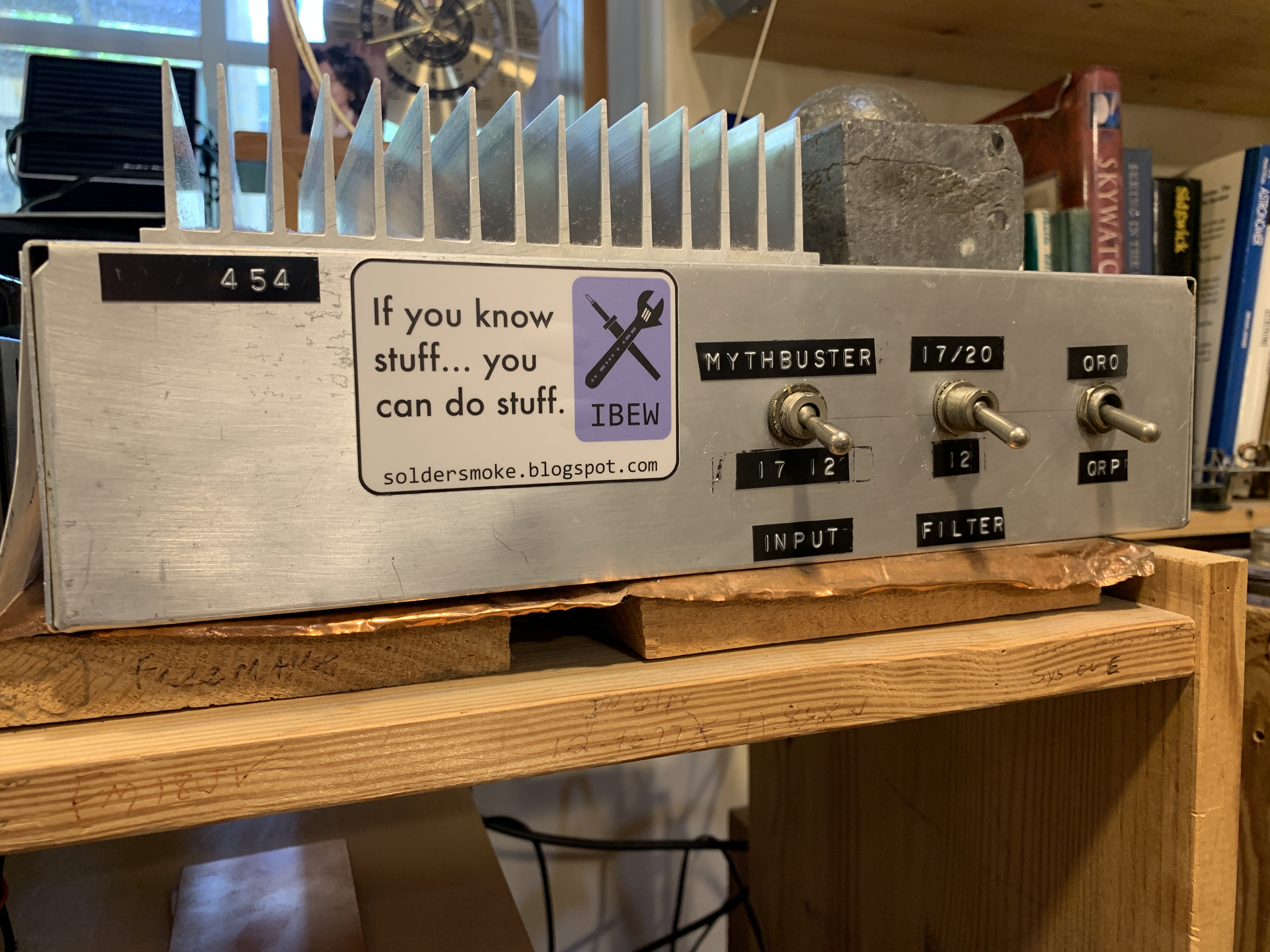
Fixing the 17-12 Rig. Parasitic VHF Oscillations with the SK3050. Good advice from Gemini. Killing NE602s. Fat Finger Syndrome -- hard to work with ICs. Different freq when on transmit -- need for .1 uF cap on pin 8. Worked South Korea -- TRGHS.
Putting the DIGI-TIA back on the air. On 40! And SW listening with the Q-31.
Hard to homebrew for 2 meters. Did some beacon experiments to Puerto Rico on last day in DR.
SHAMELESS COMMERCE DIVISION:
The importance of Patreon! Thanks! patreon.com/SolderSmoke
Mostly DIY RF! https://mostlydiyrf.com/
Universe Today Podcast with Fraser Cain. No Ads. Great stuff. Listen! https://www.patreon.com/public-rss/75186?show=1744036
Dean:
The VWS WSPR project.
Mailbag:
Ed N3EML Heard me on 40 with my Digi-Tia
Grayson KJ7UM Liked WWII training video: https://soldersmoke.blogspot.com/2026/05/radio-receivers-1942-training-film.html
Mike WN2A -- Pete Juliano is our Shifu! (Lexicographer Steve Silverman KB3SII approves,)
Todd K7TFC Thoughtful comments on ARRL "Clean Signal Initiative."
Danny ON1MWS's regen with unusual variable capacitors.
Mike WU2D S-38, Nearfest, Mu Metal. https://www.youtube.com/watch?v=YUQ4xml1dSY
Charlie NJ7V Interviews Mitch NK3H who homebrewed an SSB transceiver.
Charlie also had Don KM4UDX, President of the Vienna Wireless Society on the podcast.
Bob KD4EBM -- El Cilindro. Radioactive Hospital Waste -- basis for a Ruben Blades song. It was 1987 in Brasil. Cesium 137 left in hospital waste.
Hamilton KD0FNR Big fans of "The most interesting man in the world."https://soldersmoke.blogspot.com/2026/04/background-from-maine-on-most.html
Rhett KB4HG -- TW-100! Used on the OMRN. https://soldersmoke.blogspot.com/2026/05/the-tw-100-fly-away-transceiver-cw-ssb.html
What happened to Glenn KU4NO's homebrew rig? https://soldersmoke.blogspot.com/2018/07/a-rig-with-maximum-soul-5-band.html
Ryan KJ7KVD is listening to OLD SolderSmoke podcasts. He will build a Michigan Mighty Mite.
Will N5OLA restored a Heath SB rig. We now know why they went to HW rigs. https://www.youtube.com/watch?v=Bt2d1Ia8lqQ
Paul G0OER -- Thanks us for PTOing the HB world, but sends us a video of a unique Eddystone receiver with 39 permeability tuned coils! https://www.youtube.com/shorts/L4oQHU5_kQk?feature=share
Rick N3FJZ -- A very cool video today on his homebrew HF power amplifiers: https://www.youtube.com/watch?v=-CUVAF4HyfY
Farhan VU2ESE -- I heard from him yesterday as he was landing in Chicago.


