It is not every day that you get the chance to help a master homebrewer like Pete Juliano N6QW. But today is just such a day. Pete asks for some coding help:
The Radio Gods would be pleased if you help. The Mojo and Juju levels of all your projects would increase. If you can help, please do so.
simple SPI interface, should be all that difficult...
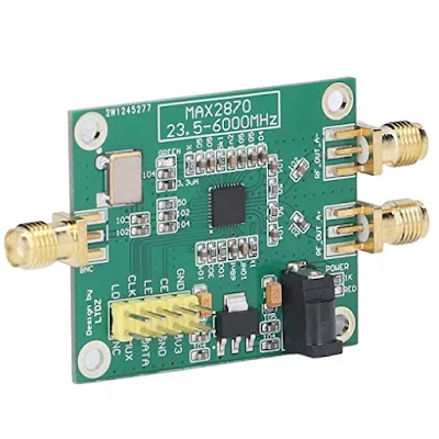
ReplyDeleteI have just looked through the MAX2870 datasheet, and while it does indeed use an SPI interface, it's not a simple task to properly calculate and set the byte values of the device's six control registers and read the single status register.
ReplyDeleteThe control registers must be set in a specific order and with the proper timing in milliseconds between them. The user's software must calculate whether or not to use the "Fractional-N" or "Integer-N" modes, what the "Feedback divider factor," "Fractional Modulus Value," "Clock Divider Mode" and "Clock Divider Value," the "VCO Feedback Mode,"RFOUT Divider Mode," and so forth and so on, should be for a desired output frequency in MHz.
I hardly know what any of those things are, let alone be able to tackle writing an Arduino or Python library that abstracts all that away so the end user can just give it a frequency in Hz and say, "do it."
Looking this over has greatly amplified my gratitude (>100dB) for under-sung heros such as Christophe F4GOJ and Paul M0XPD for their AD9850 libraries, and to Jason NT7S for his Si5351 library. Without their work--all given away freely--these devices would be unusable by all but a small fraction of radio amateurs. --Todd K7TFC
Pete,
ReplyDeleteI know I am real, real late to the party, but let me know if you still need help on this one. I am using (3) MAX2871's in a LF-3GHz Spectrum Analyzer and also (1) MAX2871 for a LF-6GHz Synthesizer with great results. This part is controlled by Arduino which receives the F,M and N registers code from a FreeBasic program, running on a Laptop. The FB program calculates FMN using a Least Common Denominator routine.
The MAX chips perform very well and their spectrum looks relatively clean. 73! WN2A