Podcasting since 2005! Listen to Latest SolderSmoke

Showing posts with label sideband inversion. Show all posts

Friday, December 2, 2022

But why? Why Can't I Listen to DSB (or AM) on my Direct Conversion Receiver?

I've said this before:  I just seems so unfair.  We just should be able to listen to DSB signals with our beautifully simple homebrew Direct Conversion receivers. I mean, building a DSB transmitter is a natural follow-on to DC receiver construction.  And we are using AM shortwave broadcast stations (Radio Marti --I'm looking at you)  to test our DC receivers for AM breakthrough.  But when we tune these stations in, they sound, well, awful.  So unfair!  Why?   Unfortunately it has to do with laws.  Laws of physics and mathematics.  Blame Fourier, not me.  

Over the years there has been a lot of handwaving about this problem.  From Doug DeMaw, for example: 

In his "W1FB's Design Notebook," Doug wrote (p 171):  "It is important to be aware that two DSSC (DSB) transmitters and two DC receivers in a single communication channel are unsatisfactory.  Either one is suitable, however, when used with a station that is equipped for SSB transmissions or reception. The lack of compatibility between two DSSC (DSB) transmitters and two DC receivers results from the transmitter producing both USB and LSB energy while the DC receiver responds to or copies both sidebands at the same time."

That's correct, but for me, that explanation didn't really explain the situation.  I mean we listen to AM signals all the time.  They produce two sidebands, and our receivers respond to both sidebands, and the results are entirely satisfactory, right?  Why can't we do this with our Direct Conversion receivers?  I struggled with this question before: https://soldersmoke.blogspot.com/2015/07/peter-parker-reviews-dsb-kit-and.html  You can see in that post that I was not quite sure I had the answer completely correct. 

It took some discussion with a fellow Vienna Wireless Society member, and some Googling and Noodling for me to figure it out.  But I think I've got it: 

Imagine a station transmitting a DSB signal at 7100 kHz with a 1 kHz tone at the AF input.  There will be signals at 7101 kHz and at 7099 kHz.  Assume the carrier is completely suppressed. 

We come along with our DC RX and try to tune in the signal. 

Remember that they heart of the DC RX is a product detector, a mixer with the VFO (or PTO) running as close as we can get it to the suppressed carrier frequency (which we can't hear).  

Lets assume that we can somehow get our VFO or PTO exactly on 7100 kHz.  The incoming signals will mix with the VFO/PTO signal.  We are looking for audio, so we will focus on the difference results and ignore the sum results of the mixing.  

The difference between 7101 and 7000 is 1 kHz.  Great! And the difference between 7099 and 7000 is 1 kHz also.  Great again, right?  We are getting the desired 1 kHz signal out of our product detector, right?  So what's the problem?  

Here it is: SIDEBAND INVERSION.  Factoring in this part of the problem helps us see the cause of the distortion that plagues DSB-DC communication more clearly. 

Remember the Hallas Rule:   Whenever you subtract the modulated signal FROM the unmodulated signal, the sidebands invert.  So, in this case, we are subtracting that 7099 "lower sideband" signal FROM the 7100 VFO/PTO signal.  So it will invert.  It will become an upper sideband signal at 1 kHz.  We will have two identical 1 kHz signals at the output.  Perfect right?   Not so fast. Not so PERFECT really.  

The perfect outcome described above assumes that our VFO/PTO signal is EXACTLY on 7100 kHz.  And exactly in phase with the suppressed carrier of the transmitter.  But if it is even SLIGHTLY off, you will end up with two different output frequencies, signals that will move in and out of alignment, causing a wobbling kind of rapid fade-in, fade-out distortion.  You can HEAR this happening in this video by Peter Parker VK3YE, starting at 6:28:

And you can see it in this LTSpice simulation.  


This LTSpice model just shows two diode ring mixers.  The transmitter is on the top, the receiver is on the bottom. The transmitter has RF at 7100 kHz at L1 and audio at 1 kHz at R1.   The receiver has the VFO at 7100.001 L7,  DSB from the transmitter at L12 with audio appearing at R4.  It is instructive to watch the output as you move the VFO frequency.  If you move the VFO freq away from the transmit carrier osc frequency you will see the distortion.  Here is the netlist for the LTSpice simulation: 


On paper, using simple mixer arithmetic, you can tell that it will be there. With the VFO/PTO just 1 Hz (that's ONE cycle per second) off, you will end up with outputs at 1.001 kHz and at .999 kHz.  Yuck.  That won't sound good. These two different frequencies will be moving in and out of alignment -- you will hear them kind of thumping against each other.    And that is with a mere deviation of 1 Hz in the VFO/PTO frequency!  We are scornful when the SDR guys claim to be able to detect us being "40 Hz off."  And before you start wondering if it would be possible to get EXACTLY on frequency and in phase, take a look at the frequency readout on my PTO.  

Now consider what would happen if the incoming signal were SSB, lets say just a tone at 7101 kHz.  We'd put our VFO at around 7100 kHz and we'd hear the signal just fine.  If we were off a bit we'd hear it a bit higher or lower in tone but there would be no second audio frequency coming in to cause distortion.  You can hear this in the VK3YE video:  When Peter switches to SINGLE Sideband receiver, the DSB signals sound fine. Because he is receiving only one of the sidebands. 

The same thing happens when we try to tune in an AM station using a Direct Conversion receiver:  Radio Marti sounds awful on my DC RX, but SSB stations sound great. 

My Drake 2-B allows another opportunity to explore the problem.  I can set the bandwidth at 3.6 kHz on the 2-B, and set the passband so that I will be getting BOTH the upper and the lower sidebands of an AM signal. With the Product Detector and the BFO on,  even with the carrier at zero beat  AM sounds terrible.  It sounds distorted.  But -- with the Product Detector and BFO still on --  if I set the 2-B's  passband to only allow ONE of the sidebands through,  I can zero beat the carrier by ear, and the audio sounds fine. 

There are solutions to this problem:  If you REALLY want to listen to DSB with a DC receiver, build yourself a synchronous detector that gets the your receivers VFO EXACTLY on frequency and in phase with the transmitter's oscillator.  But the synchronizing circuitry will be far more complex than the rest of the DC receiver. 

For AM, you could just use a different kind of detector.  That will be the subject of an upcoming blog post. 

Please let me know if you think I've gotten any of this wrong.  I'm not an expert -- I'm just a ham trying to understand the circuitry. 

Tuesday, November 30, 2021

Putting a Barebones Superhet on 17 Meters with an NE602 Converter (Video)


Armed now with a NanoVNA, I took a look at the passband of the 5 MHz filter in my Barebones Superhet (BBRX)  W4OP built it on a Circuit Board Specialist Board.  He put a 5 MHz CW filter in there;  I broadened the passband for phone by changing the values of the capacitors. Here is what the passband now looks like in the NanoVNA: 


This is what DeMaw would call an "LSB filter."  You would get much better opposite sideband rejection by using it with an LSB signal, placing the BFO/Carrier Oscillator slightly above the passband, in this case near 5.002 MHz. 

When I first built the down converter to get the 18.150 MHz signal down to the 7 MHz range (where I had the receiver running) I used an 11 MHz crystal for the NE602's local oscillator.  But this created a big problem:  18.150 - 11 =   7.150 MHz.  That is in the 40 meter band, but note:  NO SIDEBAND INVERSION.   Then in the BBRX  7.150 MHz - 2.150 MHz = 5 MHz  (the filter frequency) but again:  NO SIDEBAND INVERSION.   The signal started as a USB signal and remained a USB signal. 

I briefly tried shifting the BFO frequency to the other side of the filter passband.  If I could get it to around 4.985 MHz, it might work, but because the filter passband was so large, and because the crystal frequency was so low, I was unable to shift the crystal frequency that far.  In any case the results would have been less than ideal because of the "LSB" shape of the filter.  Back to the drawing board. 

I decided to cause one sideband inversion. 

At first I put a 25.175 MHz crystal module in my down converter.  This shifted the 17 meter phone band down to the 40 meter CW band.  It worked, but I cold hear strong 40 meter CW  signals being picked up by the wiring of the receiver (the box is plastic!).  I went back to the module jar in search of frequency that would move 17 meter phone to the 40 meter area (so I would not have to re-build the BBRX front end) but outside the actual 40 meter band.  

I ended up using a 25 MHz crystal in the down converter. 25 MHz - 18.150 MHz = 6.85 MHz WITH SIDEBAND INVERSION.  After checking on the NA5B Web SDR to see that there are no strong signals in the 6.835 to 6.89 MHz range, I retuned the output circuit on the converter and tweaked the input capacitor on the Barebones.  I shifted the VFO frequency down to 1.835 to 1.89 MHz and put the BFO at 5.002 MHz.   The receiver was inhaling on 17 meter SSB.  

One more change to the BBRX:  in his June 1982 QST article, DeMaw warned that trying to get speaker level audio out of the 741 op amp that he used would result in audio distortion.  And it did.  So I put one of those little LM386 boards I have been using into the BBRX box.  I just ran audio in from the wiper of the AF gain pot.  It sounds good.  

In effect this is my first double-conversion receiver.  I usually prefer single conversion, but this project has highlighted for me one of the advantages of double conversion for someone like me who eschews digital VFOs:   Starting with a crystal filter at 5 MHz,  with double conversion I could keep the frequency of the LC VFO low enough to ensure frequency stability.  That would have been impossible with a 5 MHz IF in a single conversion 17 meter rig.  But if I were starting from scratch for a 17 meter rig, I could stick with single conversion by building the filter at 20 MHz,  keeping the VFO in the manageable 2 MHz range. 

Now, on to the SSB transmitter.   The Swan 240 dual crystal lattice filter from the early 1960s needs some impedance matching. 

Thursday, July 22, 2021

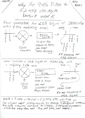
The Unicorn! A 75 LSB /20 USB Receiver (That Can't Work)


Don't get me wrong -- I'm a huge fan of Doug DeMaw.  His books and articles are a treasure trove for ham radio homebrewers.  Also, Doug was an honest guy who admitted in the preface to his QRP book that at times he did not fully understand the circuits he was building; that kind of honesty is rare,  and is very helpful to amateurs who struggle to understand the circuits we work on.  

But everyone makes mistakes, and Doug made one in his "W1FB Design Notebook."  I present it here not as a "gotcha" effort to nitpick or sharpshoot a giant of homebrew radio, but because this error illustrates well the depth of the 75 LSB/20 USB myth, where it comes from, and how important it is to really understand sideband inversion.     Here is the mistake: 


That's just wrong.  A receiver built like this will not allow you to listen to 75 LSB and 20 USB "without changing the BFO frequency." (Am I the first one to spot this error?  Didn't anyone build this thing, only to discover that it, uh, doesn't work?)

Here's a little drawing that I think illustrates why the mythical scheme will not work: 


All confusion about sideband inversion could be avoided with the simple application of what I think we should call "The Hallas Rule"

"Sideband reversal occurs in mixing only  if the signal with the modulation is subtracted from the signal that isn't modulated."  

Be careful here:   I think some arithmetic carelessness is responsible for much of the myth. Taking the difference frequency is not enough to produce sideband inversion. Read the Hallas Rule carefully:   For sideband inversion to occur, the signal with the modulation must be subtracted FROM the signal without the modulation.
--------------------------------------------- 
About the Swan 240's SSB generation scheme: 

I first stumbled on this problem when building my first SSB transmitters in the Azores.  I was using a VXO,  and a filter pulled out of a Swan 240 (5.173 MHz).  I started with VXO crystals at around 12.94 MHz.  The rig worked,  but I couldn't pull the VXO crystals very far.  So I switched to crystals at around 23.3 MHz (you can pull higher frequency crystals farther).  But look what happened:  My Carrier Oscillator frequency had been set up to receive USB signals on 17 Meters.  With the 12.94 MHz rocks, that worked fine:   18.150-12.977 = NO INVERSION.  But it all changed when I went to the 23 MHz VXO rocks:  23.323-18.150 = INVERSION!   This had me scratching my head a while.  I had to draw myself little spectrum pictures (like the one above) before I realized what had happened.  To get it to work -- to get it to produce USB on 17 meters -- I had to move the Carrier Oscillator to the other side of the passband. Good thing that Swan 240 came with TWO BFO crystals (5.1768 MHz and 5.1735 MHz). I just had to change the crystal. 

For 75 and 20 meters, the Swan 240 uses the correct 5.173 MHz filter with a 9 MHz VFO to get the happy situation of 75 meter LSB and 20 Meter USB WITHOUT changing the BFO/Carrier Oscillator frequency.  This is the Mythbuster scheme.  Unlike Doug's receiver, it works.  The scheme also works in the Swan 240 on 40 meters because for 40 the Swan rig has the VFO running from 12.073 MHz to 12.513 MHz. Here too, no change in the BFO/Carrier Oscillator  frequency is needed. But the Swan recommended a modification that would allow operation on 20 LSB and 75/40 USB!  It used a BFO/Carrier Oscillator crystal of  5.1765 MHz and a switch mounted on the front panel.  Luckily,  my junker Swan (acquired from HI8P in the Dominican Republic) had the second crystal -- mine was 5.1768 MHz.  It was that crystal that allowed me to get my Azorean SSB transmitter to work using the 23.9 MHz VXO rocks.    

Designer: Douglas Bowman | Dimodifikasi oleh Abdul Munir Original Posting Rounders 3 Column