Podcasting since 2005! Listen to Latest SolderSmoke
Sunday, December 22, 2024
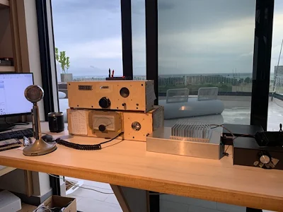
SolderSmoke Shack South -- with Mythbuster II and AN762 .1 kW Linear
Friday, December 13, 2024
SolderSmoke Podcast #255 -- Accept the HB Challenge!, DeMaw SSB, Brilliant TR-3, Tube Talk, Ground Truth, Tales of Woe, SDR RX, Pico Balloons, MAILBAG
-- Bill was on Ham Radio Workbench: https://soldersmoke.blogspot.com/2024/11/bill-n2cqr-appears-as-guest-on-ham.html Our challenge to HRWB. Gauntlet thrown down... OUR CHALLENGE HAS BEEN GRACIOUSLY ACCEPTED! We now extend the challenge to the entire SolderSmoke community: Build one of these: https://hackaday.io/project/190327-high-schoolers-build-a-radio-receiver
Homebrewing is not for the faint of heart! Accept the challenge! Build stuff!
Our question: Did Doug DeMaw ever build an SSB transceiver? Starting in September 1985 he wrote a five part series on an SSB TRANSMITTER for QST. But he prefaces it by asking, "Why would anyone build an SSB transmitter today?" He says it would be fun "for the experience and understanding it would provide." But not for use, you see... And it is not a transceiver.
Bill's theory about DeMaw, SSB,CW and sideband inversion: He was a CW guy so sideband inversion did not really matter. He could get it wrong and still make it work.
Pete's Bench:
Brilliance and the TR3. https://www.youtube.com/watch?v=2C-eYB8yFzg&t=13s
A tale of woe. Done in by a light bulb.
Thanksgiving dinner and SSB transceivers. https://n6qw.blogspot.com/2024/11/11292024-how-to-homebrew-thanksgiving.html https://www.pastapete.com/
Hybrid plans: https://www.youtube.com/watch?v=zKUjHZMf3Fs&t=5s
Dean's Bench:
Travelogue – Falcon 9 Launch
Building a homebrew T Match tuner for the end-fed long wave – sourcing the parts, winding the coil – taps, testing
VWS Makers Projects
SDR Receiver Project – starting in January
VWS Pico Balloon – Traquito - Traquito - WSPR Pico Balloon
Revisiting the 10M DSB rig
Soldersmoke listener challenge – build a DCR with KK4DAS – overview then one board a week
SHAMELESS COMMERCE DIVISION: Mostly DIY RF. Please subscribe to our YouTube Channel. And use the Amazon link on our blog. Become a Patron via Patreon (on the blog). SolderSmoke is now on Blue Sky and Threads -- follow us or at least like us there. Please turn on automatic downloads on your podcast app -- most podcast apps will only store a few episodes. This will help bump the numbers, which will improve visibility. Please give the show five stars and, if possible, a nice review on your podcast service, That will help with the discovery rate for people looking for new podcasts.
Bill's Bench:
Is "The Ground" a Myth? ARRL VP says Ground is a Myth: https://www.youtube.com/watch?v=KdX-978tvkY. Bill disagrees. Helicopter story. Refrigerator story. Original single wire telegraph system. https://en.wikipedia.org/wiki/Single-wire_earth_return
Front Panel and Freq Counter for the Mythbuster II.
Another Tale of woe: A mysterious audio problem on the 15-10 II rig. Done in by.... Duh! Comparing sideband suppression with Mythbuster I. Differences in Hfe? Notes on Mythbuster II build.
TinySA Ap -- A cure for Fat Finger Syndrome? : http://athome.kaashoek.com/tinySA/Windows/ How to get and load the Ap (you might want to start watching at 1:11) https://www.youtube.com/watch?v=zu4X5dyUlpo&t=2s General info video on the TinySA Ultra: https://www.youtube.com/watch?v=6C24RnYNOWQ&t=1143s
For the DR shack -- I got a Swan SWR-1A on E-Bay.
MAILBAG:
-- Scott KQ4AOP trying to track down the DeMaw SSB transceiver mystery. On the DC Receiver: This was my first receiver build and, it was great fun. When you finish the build and prove you are able to tune through the band, you are welcomed into the secret society! The build is the initiation.I am happy to print and ship the PTO if needed.
-- Bill WA5DSS has built a High School Direct Conversion Receiver!
-- Grayson KJ7UM liked the 1971 video on old THERMATRON AM radios: https://soldersmoke.blogspot.com/2024/11/basic-radio-circuitry-1971-film.html
-- Chris KD4PBJ sent nice electronic care package.
-- Walter KA4KXX is honored that Dean named his dog for him (Walter was just kidding)
-- Thanks to Bob W8SX for FDIM 2024 interviews.
-- Tony G4WIF insomnia driving him to podcasts. Amazed by quantity of food eaten on Thanksgiving.
-- Nice comment from Trigger about the podcast.
-- Clint says "valves" when he means THERMATRONS. Kindly asks about "Oooo Thats Awesome"
-- Eric 4Z1UG faced with a new challenge. Get well soon OM.
-- Sam WN5C and his Chat GPT AI Elmer.
-- Paul VK3HN on using AI for electronic design. I dunno... Apocalypse Now in the DR?
-- Tommy SA2CLC FB old military gear on QRZ site. Helps with HP8640B repair.
-- Mike WN2A nice comments on Chappy Happy's FB Tezukuri DC RX https://soldersmoke.blogspot.com/2024/11/tezukuri-and-chappy-happy-amazing.html
-- Allison KB1GMX. Good info on ground truth.
-- Phil W1PJE Had to throw out 15 test leads. Fake wire!
--Todd K7TFC Thoughtful comments on AI and ChatGPT, Help with TinySA Ap
-- Steve KW4H Boatanchor guy. Likes that we often scratch our heads trying to understand.
-- Nick M0NTV built a 40 meter DC receiver: https://soldersmoke.blogspot.com/2024/12/a-40-meter-direct-conversion-receiver.html
-- Dave AA0KU asks about CCI amp (AN762) Also woking on Drakes.
-- Jack (Dhaka Jack!) F4WEF/AI4SV Good thoughts on how to bolster SolderSmoke's ratings.
--Tobias thinks the decline IS ALL HIS FAULT!
-- Tony VE7JUL building a TJ DC RX. Go Canada! Dean says: 3D print PTO former at 110%
-- Jim KI4THC getting his uBITX on the air.
10S November 23, 2024 1517Z SV1AER Kostas in Athens. Said a very sincere “Oh my goodness! Congratulations! That is not a very common thing!” when I told him rig was homebrewed. Nice fellow. Great response.
Saturday, November 16, 2024
Video -- Mythbuster II Rig Gets a Front Panel -- Circuit Build Almost Done
Wednesday, November 13, 2024
SolderSmoke #254 (Audio and Video Versions): Australian Hex Beam Eaters, Fake Wires, Hybrid Rig, Antennas, Mythbuster II Transceiver, Mailbag
November 13, 2024
SolderSmoke Podcast #254 is available:
Audio Version here: http://soldersmoke.com/soldersmoke254.mp3
Video Version here: https://www.youtube.com/watch?v=ZiZwWY1CQgI
Opening: Disturbing news from Australia! VK5RS reports that his Hex beam was EATEN by Cockatoos! So stop whining about your HOA problems, OK? It could be much worse!
FAKE WIRES FROM CHINA! Oh no! Even the wires? There is a good video from Mattias. I have it on the SolderSmoke blog. https://soldersmoke.blogspot.com/2024/11/clip-leads-made-with-fake-wire-buy-good.html Important to note that Parts Candy doen't have this problem. Buy your test clip leads from our sponsor, Parts Candy. Link in the column on the right or go to partscandy (that's one word).com
Bill's appearance on the Ham Radio Workbench. (Bill made some overly harsh comments about radio rejuvenation, and was trying to make amends.) But now we throw down the gauntlet. WE CHALLENGE the HRWB guys to build -- to homebrew - our TJ DC RX. They will experience JOO, JVO and the elite status that comes with having built their own ham radio receiver. And if they go on to build a 10 minute transmitter, they can use it for CW contacts. Like on POTA (Thomas!)
Anniversary approaching: In August 2025 we will mark 20 years of the SolderSmoke podcast. And we have already passed TEN YEARS OF JULIANISMO! Pete joined the podcast on May 26, 2013. Thanks Pete!
Question for the group: Which SSB transceivers did Doug DeMaw build?
Pete's Bench: Thermatron-Transistor Hybrid Goodness. https://n6qw.blogspot.com/2024/10/blog-post_20.html
Dean's Bench: The new Hex Beam (watch out for Cockatoos!) Now that Dean and I both have Hex Beams, we plan on pointing them at Southern California in an effort to talk to an elusive RADIO GENIUS. Stay tuned!
SHAMELESS COMMERCE: Please link to our blog and podcast! Please become a Patreon supporter (I have been posting special content there). Be sure to make use of the great boards, parts and kits available at Mostly DIY RF. Still use the Amazon link on the SolderSmoke blog page.
Bill's Bench: The new Mythbuster II (20 meters only). Built in about 3 weeks. On-the-air, while still on the bench! Worked Euope and South Africa QRP. https://www.youtube.com/watch?v=6o9QerQ7jzg
Getting another CCI amp for the Dominican Republic.
MAILBAG:
-- Paul VK3HN, talks about the nice sound of the Mythbuster II's receiver, and a new QRP rig from Dave Benson K1SWL.
-- Rick N3FJZ sent some very kind words in support of the SolderSmoke podcast. Thanks Rick.
-- Chris KD4PBJ sent us a very nice message. Thanks Chris.
-- Kevin from Belgium sent a nice blog post in support of SolderSmoke.
-- John WB4BTL spotted his old call (from 1974) in my Novice Log.
-- Dave KD2E spotted his Novice call in my Novice log: WN2TBB. He also saw a good friend WN2EHE.
-- Mehmet who has the awesome and useful WEBSDR of NA5B helped me with a Facebook problem. Thanks Mehmet!
-- Mike WN2A asked about the Yaesu FT-101 9 MHz VFOs.
-- Phil W1PJE (from MIT!) writes about old broadcast radio shows. And some really nice words of encouragement.
-- Grayson KJ7UM sent kind words of encouragement, and great background on hybrid rigs.
-- Peter VK3TPM writes about the decline of blogging, but notes that blogs are useful repositories.
-- Todd K7TFC sent me some additional Mostly DIY RF boards. Thanks Todd!
-- Ed DD5LP/G8GLM Kind words on SolderSmoke, nice info on the G-QRP 50th edition.
-- Bill AH6FC Encouraging words and good info on solar. Mahalo Bill!
-- Michael AG5VG Building LC VFOs for 7 MHz. FB OM!
-- Bob K7ZB An EE who likes the treatment of mixers in the SolderSmoke book.
Friday, November 8, 2024
Video Update on the Mythbuster II 20 meter SSB Transceiver
We will discuss this further in an upcoming Ham Radio Workbench Podcast, and in SolderSmoke Podcast #254 (mid-November 2024)
Saturday, November 2, 2024
More Background on the Mythbuster II Rig (and a short video)
Above is a short clip of me hearing an old friend on the new receiver. TRGHS.
A couple of guys on Facebook asked for a schematic for this rig. I don't really have one -- as you will see it is a collection of different circuits from lots of different sources. I was also thinking that if you need a schematic for a rig like this, you probably shouldn't try to build a rig like this. But in an effort to be nice, I supply here some background info on some of the circuitry and parts sources. And no, I don't have BOMs nor Gerber files.
More info on the Yaesu VFO is here:
https://soldersmoke.blogspot.com/2021/07/mythbuster-video-3-using-vfo-from-yaesu.htmlAs for the tape, I got mine from Amazon. It has conductive adhesive:
https://www.amazon.com/gp/product/B07QQJ4MX1/ref=ppx_yo_dt_b_search_asin_title?ie=UTF8&psc=1
Wednesday, October 30, 2024
Bill N2CQR Builds Yet Another Mythbuster Transceiver
This one is for 20 meters (no need for 75) and will go to the Dominican Republic.
6 crystal filter at 5.2 MHz. VFO from old Yaesu FT-101 Termination Insensitive IF amplifiers using boards from Mostly DIY RF No RF amp ahead of the mixer. First mixer is homebrew diode ring. Bandpass filter has 4 LC circuits. Steep skirts. Low insertion loss. Bal Mod/Product detector has two diodes (singly balanced) Carrier osc is crystal controlled and homebrew. Audio amp starts with a 2N3904 amplifier followed by an LM386 board. Transmitter portion will be done next.Monday, September 30, 2024
Homebrew Receiver -- AG5VG's 20 Meter "Mythbuster" Receiver
Friday, May 17, 2024
Band Imaging Rigs (Receivers and Transceivers) -- Video from WA7MLH
Wednesday, March 13, 2024
Using the RF Power Amplifier of the BITX40 Module
Thursday, December 14, 2023
Mythbuster Video for the Lamakaan Amateur Radio Club of Hyderabad, India
Friday, October 6, 2023
A Pretty Good Troubleshoot -- Fixing the Transmitter in my 75/20 meter Mythbuster Transceiver -- Mind the Gap!
All of a sudden the transmitter in my 75 & 20 meter dual band homebrew Mythbuster transceiver stopped working -- there was no output at all. I went into troubleshooting mode.
The first clue was that the receiver was working fine. This meant that many stages of the rig were taken out of suspicion: It probably wasn't the VFO, the first mixer, the BFO/Carrier Oscillator, the second mixer, or the bandpass filters. Nor was it any of the receive sections in the bidirectional amplifiers I was using.
Suspicion fell on the power amplifiers and on the transmit sections of the bilateral amplifiers.
With the output going to a dummy load, I put the rig into transmit mode and put a bit of audio into the mic jack. Then with the 'scope I started to work my way back from the antenna jack. I wasn't seeing anything. Then I got back to the transmit side of the TIA amplifier between the crystal filter and the mixer. There was a strong signal at the input, but nothing at the output. Bingo! I had found the faulty stage. But where, exactly, had this stage gone wrong?
There are three transistors on each side of a TIA amp (see schematic above) -- I just started from the input of the first one with my scope probe and moved through the circuit. Finally, at the output of the last of the three amplifiers, the signal stopped. I knew I was very close to the problem.
Looking at the components, suddenly I could see the problem: At the output there is a 47 ohm resistor (R2 in the circuit diagram above) and a .1uF cap in series. The cap went to a Manhattan pad. But when I looked at it closely, the lead was kind of floating above the pad. See it?
And when I moved it, the connection between the 47 ohm resistor and its pad seemed quite flimsy.
I quickly replaced both components and was back on the air.
I don't really know how or why the lead to that capacitor broke. Maybe I had bent it repeatedly, to the point of weakness, and, over time, it just let go.
Whatever the cause, I found this to be a satisfying troubleshoot and repair. It required me to think a bit about what could be wrong, and to use some test gear to zero on on the faulty component.
Monday, July 10, 2023
Martein's Bandpass Filters - PA3AKE
Before I built Martein's filter, my bandpass had been inadequate. Looking at the signals coming out of the diode ring mixer in my 15-10 rig, I realized that when I was on 15, there would also be an output on 10. And vice-versa. These outputs would have to be knocked down by the bandpass filters. I had been using simple dual tuned circuit filters. But when I looked at the filter shapes of these filters in NanoVNA, I could see that On 15 the 10 meter signal was only down about 20 db. And on 10 the 15 MHz output was also down only by about 20 db. That's not enough. Take a look:
Monday, September 5, 2022
Why Do Some VFOs Tune More Linearly Than Others?
This has been one of the major complaints about our beloved analog LC VFOs: The frequency tuning on these circuits is often not linear. For given amount of VFO frequency dial turn you can get vastly different changes in frequency. At one end of the tuning range the frequencies are nicely spaced and tuning is easy. But at the other end of the tuning range all of the frequencies are bunched together. This is one of the problems that leads some homebrewers to defect to the sad land of "digital VFOs."
But wait. It appears that the old designers found a solution to this problem. Just look at the tuning dial of my HT-37. The frequencies are all spaced out evenly. How did they do that?
I had been thinking that this success may have resulted from Hallicrafters' engineers using the series-tuned Clapp circuit. Here the main frequency determining element is a series-tuned LC circuit and not the parallel tuned LC circuit that we see in the more commonly used Colpitts circuit.
But hold on -- how could that be? The frequency bunching problem that we attributed to the Colpitts circuit must also exist in the Clapp, right? I went back to SSDRA where there was a good discussion of Colpitts and Clapp VFOs. The advantage of the Clapp was said to be in its use of a larger value coil which helped minimize the effects of stray inductances. But there was no mention of the Clapp offering improved linearity in tuning.
I have in front of me two transceivers: The Mythbuster uses a 9 MHz Clapp circuit (see below). The 17-12 rig uses a Colpitts Circuit. I checked the tuning linearity of both. Both appeared quite linear in tuning, with no real difference between the two.
Then I looked at the tuning capacitor in the Mythbuster 17-12 rig. It came out of an old Hallicrafters transmitter, probably the HT-44. I looked closely at the stator and the rotor plates. Both are curved. I'm guessing that this may yield a more constant change in capacitance for a given movement of the main tuning dial.
Next I opened up the VFO on the Mythbuster. (It is the VFO from an old Yaesu FT-101.) I couldn't see the stators very well but it appears that their shape is different from the square shape we often see in variable capacitors. Could it be that this variable capacitor was also made to provide linear tuning?
Back in 2013 Norm Johnson wrote about all this in the Antique Radios.com forum:
A capacitor that has uniform increase in capacitance with rotation will have the stations at the high end of the band squeezed together. Another type known as the straight-line frequency variable capacitor has, as you might guess, a characteristic that gives even spacing of frequencies with shaft rotation. These were popular in the 1920's but weren't very good for superhets where you needed to have a dual section capacitor that would tune both the RF and local oscillator, and have them track each other properly. The midline variable capacitor is more compatible with a superhet, and easier to make both sections track properly. This is the type that you see in most receivers from the late 1930's to the end of the tube era. They don't have quite the equal spacing between stations across the band that the old straight-line frequency caps had, but they're much better than the variables that change capacitance linearly with rotation.
I wrote an online calculator that helps in the design of the tuning. It shows what frequency range you'll get with a specific type of variable capacitor, including the effects of padder and trimmer capacitors. It also displays a dial scale that shows how the frequencies are lined up accross the dial.
http://electronbunker.ca/eb/BandspreadCalc.html
Steve W6SSP also provided some really good info back in 2013:
There are three types of open, variable plate caps;
SLC= straight line capacitance where the capacitance varies linearly,
these are the most common and have half-circle plates
SLF= straight line frequency where the plates are tapered to allow
for linear tuning of the frequency
SLW= straight line wavelength, you get the idea...
SLF and SLW caps have oblong plates.
The effect on tuning a receiver can be dramatic. One example is the
Hammarlund SP series of receivers where the ham bands are very
compressed at one end of the tuning range. They used SLC caps
in the VFO. On the other hand rigs like the Kenwood TS-520
and FT-101 series have linear tuning across each band. These use
SLF variable caps. Most old 1920's battery radios used SLW
where stations were identified by their wavelength.
Steve W6SSP
The Drake 2-B also has perfectly linear tuning. I looked at the manual: "The tuning condenser is of special design..." I'm guessing that they used an SLF variable capacitor. The 2-B had no need for ganged capacitors -- the "preselector" was tuned via a separate front panel control.
I looked at the tuning dials on my Hammarlund HQ-100 receiver. It is fairly linear in its tuning, but not as linear as the HT-37 or the Drake 2-B; on all of the tuning ranges the frequencies seem to spread out a bit at the lower end. My guess is that Hammarlund used the midline variable described above by Norm Johnson. The HQ-100 did use a ganged variable cap, with one section tuning the RF amplifier and the other tuning the local oscillator.
Monday, April 25, 2022
75/20 - 17/12 Two Homebrew Rigs in Scrap-Wood Boxes
Friday, February 25, 2022
Split Stator Temperature Compensation Also Used in Yaesu FT-101
Thursday, December 30, 2021
McCoy SSB Crystal Filters (1963) -- But Apparently NOT the Real (Lew) McCoy
Friday, December 10, 2021
The Lamakaan Annual Radio Convention Starts Today!
Here's a time zone converter: https://www.timeanddate.com/worldclock/converter.html?iso=20211211T043000&p1=505&p2=250&p3=137
Here is the Lamakaan Club's YouTube Live Channel. https://www.youtube.com/watch?v=cRznKwGgvDo
I don't know how we might be able to watch or listen via the QO100 satellite. The U.S. is not in the footprint of this bird. But there is a good WEBSDR receiver run by BATC and AMSAT DL: https://eshail.batc.org.uk/