I like the homebrew spirit in this one, how it started out as a Direct Conversion receiver and expanded into a full double sideband transceiver.
Showing posts with label 40 meters. Show all posts
Showing posts with label 40 meters. Show all posts
Friday, April 17, 2026
Wednesday, June 25, 2025
WD4CFN Makes Contact Using the SolderSmoke Direct Conversion Receiver and a Michigan Mighty Mite

Saturday, June 21, 2025
My Eleven Contacts using the SolderSmoke Direct Conversion Receiver -- It is NOT a toy!

I have made 11 contacts using the SolderSmoke Direct Conversion receiver. Ten of the 11 were after June 3, 2025. This was in very casual operation, operating with less than 1 watt with a dipole antenna.

Alan W4AMV
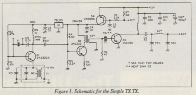
1. The first of course was back in February 2023 with W4AMV. On this one I was using a simple "10 Minute Transmitter" that I threw together thinking that I would use it to demonstrate the receiver to our high school students. "Wait a minute," I thought. I called CQ and W4AMV answered. I was running about 100 mW. He too was using homebrew gear. https://soldersmoke.blogspot.com/2023/02/first-qso-with-high-school-receiver-100.html
2, 3, 4. On June 4, 2025 I again fired up the 10 minute transmitter. My T/R scheme was VERY simple: I have an MFJ coax switch that I use to select the rigs that will connect to my various antennas. On the antenna switch I selected my 40 meter dipole. I ran two pieces of coax from two different positions on the MFJ switch. One I marked RX, the other TX. The transmitter and the receiver were working off 9 volt batteries. I quickly worked N2WJW. Gil in New Jersey. But I noticed that the 10 Minute rig was drifting. So I pulled out my trusty old Tuna Tin 2 transmitter and used it to heartlessly replace the 10 Minute Transmitter. Now with SEVERAL HUNDRED milliwatts, I worked W2XS, John in New York on June 5, 2025. Later that same day I worked N9FGC in Indiana.

K1OA's Rig
5. My most amazing contact came on June 7, 2025. Here is my log entry: 40CW K1OA First 2 way contact with station also using a SolderSmoke DC Receiver!At around 0630 EDT on June 7, 2025 I heard K1OA calling CQ on 7030 kHz CW. This was exactly where I had a crystal. I called him, but he didn't hear me. I sent him an e-mail. We tried again -- he heard me calling him and I heard him responding by calling me, but I don't think we succeeded in exchanging signal reports. It was close, but no cigar. I had to walk the dog. Scott and I agreed to meet on 7030 kHz at 0730 EDT. Arggh. There was a QSO there. I thought we might have to try to change frequency, but this would have been tough because both of us were crystal controlled on transmit. Fortunately, the contact on 7030 kHz wrapped up. Scott called me, I responded, and we were able to exchange signal reports. I was so excited that I almost forgot to hit the record button on my phone. But I caught the last minute or so.This was really something. This really goes to prove what Dean and I have been saying all along: this receiver is not a toy! It can be used for real ham radio contacts. And now we have had these receivers on both ends of a contact. For transmit, Scott was using a KA4KXX transmitter with about 3 watts output. I was on my Tuna Tin 2 at about half a watt output.

Jim W1PID
6, 7, 8. Later on June 7, 2025 I worked an old friend, Jim W1PID. Jim is a friend of Homebrew Hero Mike AA1TJ, and was involved in Mike's effort to cross the Atlantic with a voice-powered rig. Jim also was one of my contacts with the ET-2 QRPppp rig. I also worked WZ2J Vin in NJ. I also worked John W2XS again.

Mike WB8VGE
9. June 11, 2025 (Really evening of 10 June 2025) Famous homebrewer, Anchorologist, Heatkit authority and fellow member of the QRP Hall of Fame Mike Bryce called me! 40CW 0034 WB8VGE Mike Bryce came back to my CQ! Mike wrote: Nothing like quartz locked frequency control!You know it sounded pretty damn good at 500mW. You were holding your own until QSB would take you out in a deep fade. But all in all, one hell of great QRP QSO.I was running my Ten Tec Scout that I had just put back together a couple of days ago. Got around to putting the case back on it tonight, and had it cooking in the back ground just listening to the stations come and go. I had worked a few POTA stations near by and found a quite spot. I was working on a project when I heard your CQ through the din of the 40M band. Glad I took a break and worked your QRPp signalbest 73 QRP # 4816 You get a QSL for that QSO!
Here's my post about Mike, WB8VGE: https://soldersmoke.blogspot.com/2018/09/wb8vge-on-qso-today-qrp-hb-boatanchors.html
10. Around June 11, 2025 I worked W4MY in a contest.
11. On June 12, 2925 I worked some DX with the rig. It was VA3ICC, Ian in Ontario.
Ian VA3ICC
All of this reinforces something that Dean KK4DAS and I have been saying all through this build process: this little DC receiver is not a toy. It can be used as a serious ham radio receiver and it can -- even when paired up with a very low-power crystal-controlled transmitter and a simple antenna -- make some great ham radio contacts.
Saturday, June 7, 2025
A FIRST! K1OA Contact with N2CQR -- All Homebrew with SolderSmoke Direct Conversion Receivers on Both Ends
At around 0630 EDT on June 7, 2025 I heard K1OA calling CQ on 7030 kHz CW. This was exactly where I had a crystal. I called him, but he didn't hear me. I sent him an e-mail. We tried again -- he heard me calling him and I heard him responding by calling me, but I don't think we succeeded in exchanging signal reports. It was close, but no cigar.
I had to walk the dog. Scott and I agreed to meet on 7030 kHz at 0730 EDT. Arggh. There was a QSO there. I thought we might have to try to change frequency, but this would have been tough because both of us were crystal controlled on transmit. Fortunately, the contact on 7030 kHz wrapped up. Scott called me, I responded, and we were able to exchange signal reports. I was so excited that I almost forgot to hit the record button on my phone. But I caught the last minute or so. See above.
This was really something. This really goes to prove what Dean and I have been saying all along: this receiver is not a toy! It can be used for real ham radio contacts. And now we have had these receivers on both ends of a contact. For transmit, Scott was using a KA4KXX transmitter with about 3 watts output. I was on my Tuna Tin 2 at about half a watt output.
Thanks Scott! And thank you Walter!
Friday, June 6, 2025
A Tale of "Ten Minute Transmitters" and "Tuna Tin Twos": N2CQR Goes Back to CW QRP!

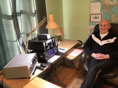
Inspired by K1OA and KA4KXX, I put the SolderSmoke DC receiver to work on the CW portion of 40 meters. At first I used a very (perhaps overly) simple "Ten Minute" transmitter. On June 4, 2025 I worked N2WJW in New Jersey. But the transmitter drifted as it got hot. So I switched to the more robust Tuna Tin 2 (TWO transistors!) and worked W2XS in NY and N9FGC in Indiana on June 5. With both transmitters I was "rock bound" -- crystal controlled. Power out was always less than 200 milliwatts. Antenna was a low to the ground dipole. The receiver was powered by our beloved 9V battery. The transmitter had a second 9V battery. Some observations: First, even if you CAN hear other signals, the different tones allow your brain to seperate them out (this has long been known to CW operators, but might not be readily apparent to newcomers). So even if the DC receiver is broad in frequency response and even though it IS also receiving the other side of zero beat, you can make CW contacts (unless, of course, another station is on a frequency that produces exactly the same tone as the one you are trying to work), even at very low power . Second, you don't always really have to be right on the other station's frequency. Here's why: If he is looking he can see you in his waterfall! So that SDR waterfall is now a friend to crystal-controlled HDR operators. Who would have thought? Above is a picture of the my station with the Ten Minute transmitter. See the notes I wrote on the QSO with N2WJW.
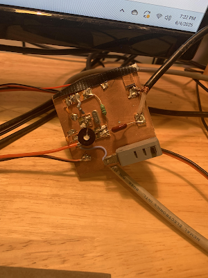
Ten Minute Transmitter (the gray thing is a CW key)

Direct Conversion Receiver

Tuna Tin 2 that replaced the Ten Minute Transmitter
Note battery and crystal
Tuesday, February 25, 2025
Calvin KE8ICE's SolderSmoke Direct Conversion Receiver

Calvin KE8ICE said that building this receiver marks his transition from a kit assembler to a homebrewer. FB!
Check out this short video of Calvin's receiver in action:
https://www.youtube.com/shorts/BbcBVmmKygw
Thanks Calvin!For more details on this project, and info on how you could build this receiver see:
Join the discussion - SolderSmoke Discord Server:
Documentation on Hackaday:
https://hackaday.io/project/
SolderSmoke YouTube channel:
Tuesday, February 4, 2025
Mr. Carlson Restores a BC-348 -- But 40 Meters Sounds Very Weak. Why?
Mr. Carlson mentions that he is a ham radio AMer. He is also on SSB, but AM is, he says, his preferred mode. FB.
I got a real chuckle about the MVC switch position on the front panel. "Manual Volume Control" like "Manual Gain Control." I thought I had invented this term. You know, "real hams control their gain manually." This is why Farhan never put AGC in the BITX20. But it seems the Army Air Corps was way ahead of me with the BC-348.
Mr. Carlson makes it sound (!) like the Dynamotors are a thing of the past. Not true. Every Saturday morning I listen to the Old Miltary Radio Net and hear a number of Dynamoters spinning in the background. One belongs to Buzz W3EMB who uses a BC-348. Buzz has an SDR attached to the IF of his BC-348, which I think is an admirable mix of the old and the new. Those BC-348s are, after all, quite old. WWII old -- like 85 years old. And still working.
Paul has a good discussion of the importance of short lead length, and of mounting shielded capacitors properly, and of the usefullness of a good groundplane under the capacitor. Go Manhattan boards! Paul's presentation on how to identify the outside foil of a capacitor was very good, but I was wondering if you could also find out by using a file to remove some of the yellow insulation, then test with a DMM to see which terminal is connected to the foil.
"Lots of times you have to add solder to remove solder." Indeed.
The importance of testing for BOTH capacitance and leakage. Yes.
But why bother with "period correct" internal wiring harnesses, when you have already put a bunch of modern caps in there? I mean, I'm in favor of the re-capping, but this seems inconsistent with the need for "period correct" internal wiring harnesses.
When Paul first fired up the receiver, I was hoping he would disconnect the antenna to see how much band noise was getting through.
When Paul got to the IF alignment, he spoke of the dangers of working on energized high-voltage gear. I had been thinking about getting a BC-348 myelf, but Paul's comments reminded me of why this is probably not a good idea for me. Paul's comments about "knowing where your hands are" is on target. "One hand behind the back, " is a good rule for this kind of energized testing -- this will help prevent current from a mishap from flowing through your chest.
I may have more comments later. Off to the beach now.
Back from the beach:
"Contrary to popular belief, the simpler the receiver, the better they hear." Amen Mr. C.
Paul's heroic cleaning of the 915 kc crystal made me feel like a wimp for not having tried to do this with some "bad" 455 kc rocks I was given while trying to build the Mate for the Mighty Midget receiver. I may go back to those crystals and try to clean them as Mr. C did.
The grand finale of this 2.5 hour video was, as expected, a demonstration of how good it sounds. But unfortunately it did not sound good. Paul tuned through the 40 meter band and I heard NO CW signals. I didn't even hear FT8. There were a few anemic SSB signals and, as he reached the upper portion of the band some very weak AM broadcast signals. I didn't even hear CHU Canada's time signal. Huh? Why? Our very simple homebrew Direct Conversion receiver sounds a LOT better than that. I mean look at the sweep of 40 meters that I did using only a simple dipole: https://soldersmoke.blogspot.com/2024/12/an-evening-bandscan-on-40-meters-using.html Why is there such a big difference in performance?
Could it be the antenna that Paul was using? He was on what he calls the 369 antenna. Could there be a problem in the receiver? Could it be band conditions?
Saturday, January 4, 2025
Donnie WA9TGT's Direct Conversion Receivers

Donnie WA9TGT writes:
I recently built my first basic 40 meter (DC receiver) from http://www.qrpkits.com/ that uses the common SA602 & LM386 chip combo with Varactor diode tuning. I didn’t want to scratch build a DC Rx simply because I first wanted to build up this simple kit with its included PCB and at least play with it a little just to see if it was something I mite wanted to further pursue. I’ve since decided yes I want to, even with all a DC receivers short comings. It’s was nearly as rewarding hearing my call being sent back to me for the very first time coming through this little DC Rx after calling CQ as it was back in 1966 during my very first Novice contact.

Saturday, December 21, 2024
KE5HPY's Altoids Direct-Conversion Receiver for 40 Meters

Click on the image for a much clearer view.
It is a thing of beauty. You can see all four stages in there. There is the Bandpass Filter in the upper left. Below that is the VFO. In the center you can see the SBL-1 mixer. Off to the right is the audio amplifier. FB Chuck!
Chuck KE5HPY writes:
Allow me to add an endorsement of the joy and practicality of the DC receiver. Whether XTO, VFO or DDS, ring diode mixer, or Polykov, the DC IF concept is a real winner. They really deliver wonderful audio and clarity that is very satisfying for homebrew builder.
Thought you might enjoy these photos of a 40 m receiver and built 10 or so years ago. The design is straight out of EMRFD. At that time, the Altoid tin craze was in full swing and this is one of several projects I stuffed in a tin. This compact receiver has traveled on lots of camping and kayak trips where it delivered good DX reception using only a 30 foot piece of wire for antenna running back to the tent. It’s fun to hear intercontinental QSOs when you’re in the middle of nowhere. With my 40 m dipole attached at home, I think this little rig can hear anything my Icom hears.
It’s great that you’re promoting this practical technology. Keep up the good work.

Wednesday, December 11, 2024
An Evening Bandscan on 40 Meters using the High-School Direct-Conversion Receiver
This video shows how useful this receiver really is. Build one of these!
Monday, December 9, 2024
Listening to 40 meters on the DC Receiver -- And I Heard a Distinguished Homebrewer!
I made the video above to show postential builders how useful our Direct Conversion receiver really is. Late in the video (starting at 11:17), I heard a station calling CQ. It was N4QR. A check of QRZ.com shows it was Bob Null. Here is picture from Bob's QRZ page:

Check out the old general coverage receiver and -- wait for it -- the homebrew thermatron transmitter. TRGHS.
Google led me to this amazing video by Stever N4LQ that describes a book that N4QR put together on how to build thermatron transmitters from Junkbox/Hamfest parts:
Steve N4LQ is in contact with Bob N4QR and asked him which transmitter he was using when I heard him. Bob said he thinks it was his 30 watt 807 final transmitter.
Thanks Bob. and thanks Steve!
Saturday, December 7, 2024
My Receiver Doesn't Work Right! What Should I Do?

An early version of our DC receiver. Note the tuning guide under the grey tuning knob.
We prepared this for use by the high school students who were building direct conversion receivers. Unfortunately none of them got to the point where they would use this little article, but given the fact that a number of people are now engaged in direct conversion receiver projects, I thought it would be a good idea to post this here. Also, much of this applies more generally to receiver problems.
My receiver doesn’t work right!
What should I do?
First,
relax. You will be able to get it to
work. The design is good, people around
the world have built this receiver, and you will be able to get it to work. But homebrew radio is not plug-and-play
radio. Sometimes a new receiver needs
some tweaking, peaking, and coaxing.
Realize that the 40 meter band has its ups and downs. The downs usually come at mid-day. The sun’s position high in the sky causes a build up of the D layer of the ionosphere. This tends to absorb radio waves. So signals are often weak at mid-day. Signals will be much stronger in the morning, and in the evening.
Can you hear the “band noise” when you connect your antenna? This sounds like hiss or static. Some of this is the result of thunderstorms in Brazil. Some of it is from events far away in the cosmos. Some of it comes from the weed whacker down the block! But if you can hear this noise, that is a very good sign that your receiver is working. The signals you are looking for will be stronger than this band noise.
Where are you tuning? Your receiver tunes from about 6.8 MHz (with the screw all the way our) to about 7.8 MHz (screw all the way in). But we are only really interested in the ham frequency band between 7.0 MHz and 7.3 MHz. Try to tune your receiver near the middle of the tuning range (with the screw about half-way in). You should hear morse code from about 7.0 to 7.06 MHz. Then you should hear strong digital signals at 7.074 MHz. Tuning further up (screw going in) you should start to hear hams speaking to each other using Single Sideband. At first they will sound like Donald Duck.
Sometimes you will only hear one side of the conversation. That is normal. The other station may be either too far away from you, or too close to you. You may be outside his or her skip zone.
One very
obvious thing to check: How is your
battery? Is it drained, or is it still
at about 9 volts? You may need to
change it.
How is your
antenna? It doesn’t have to be fancy or
elaborate. 33 feet of wire will
do. But it does need to be up in the air
a bit. And you need to have the 33 foot
counterpoise wire connected to the ground (on the PC board). With many pieces of consumer electronics
antennas are kind of optional – the devices will often work without them. Not so with ham gear. Antennas are important. If you are not receiving signals, it may be because of your antenna.
Wednesday, December 4, 2024
Challenge Accepted! Why we Designed the High-School Direct-Conversion Receiver the Way we Did

Dean KK4DAS's Beautiful DC Receiver
The folks over at Ham Radio Workbench have graciously accepted the challenge issued in our last podcast: that they scratch-build homebrew the 40 meter Direct Conversion receiver that Dean KK4DAS and I designed for local high school students. We want to help our brothers over at HRWB. For example, we may be able to supply a few of the 3D printed PTO coil forms. Here is some background information on the project.
Details on the project can be found here:
----------------------
Design Decisions in the Direct
Conversion Receiver
Why did we do it this way?
In thinking about how to design this receiver, we had to
make early design decisions on almost every stage. Here are some of our key considerations.
VARIABLE FREQUENCY OSCILLATOR:
Normally we might have used a variable capacitor to change
the frequency of this oscillator. But
variable capacitors are now expensive and hard-to-source. Our friend Farhan in Hyderabad used a simple
variable inductor for this purpose in his “Daylight Again” transceiver. The
coil form for this part could be 3D printed.
A metallic screw would vary the inductance as it is screwed in and out
of the coil.
We also decided to use the same simple Colpitts oscillator
circuit used by Farhan in his own high school direct conversion receiver. This circuit is unusual in that the feedback
capacitors are also the frequency determining elements (along with the variable
inductor). This simplified the circuit
and reduced the parts count, and proved to be remarkably stable.
For the VFO buffer we used the simple JFET buffer from
Farhan’s Daylight Again design.
Based on suggestions from other radio amateurs, we developed a simple frequency readout based on the position of the end of the tuning screw (how far in or out?).
We selected the 40 Meter band for this receiver because we
thought it would be easier to get the VFO stable on this frequency, and because
Farhan had built his receiver for 40 meters.
MIXER:
At first we hoped to use a simple singly-balanced mixer
using two diodes and a single trifilar transformer. But we found unacceptably high levels of AM
breakthrough (mostly from Radio Marti on 7335 kHz) when using this
circuit. So we switched to a diode
ring. This required two more diodes and
an additional trifilar transformer. We
believed the students would have great difficulty building and installing two
trifilar transformers so early in their building experience. So we used transformers that had been wound
in Hyderabad by a women’s collective employed by Farhan, and developed
a scheme for fool-proof installation of these transformers.
We also found that the mixer needed a diplexer at its output
– this would provide a 50 ohm termination at all frequencies and would result
in much cleaner action by the mixer and greatly reduced AM breakthrough from
Radio Marti. We used the same circuit
used by Roy Lewellen W7EL in his Optimized Transceiver circuit.
BANDPASS FILTER:
This was the simplest board in the project but it required
the students to wind two coils on toroidal cores. A simple dual-tuned circuit design would be
sufficient. We used component values
from the QRP Labs website. We showed
them how to wind the coils, and made a video about the technique. Students used a simple Vector Network
Analyzer (Nano VNA) to tune the filter.
AUDIO AMPLIFIER:
We had to make several design decisions here. First, we rejected the idea of using an IC
amplifier like the ubiquitous LM-386. We wanted this to be a completely analog
and discrete component experience. Then we rejected the idea of using a
push-pull output circuit. While this
would have eliminated the need for an audio output transformer, it would have
resulted in a more complicated circuit. In the end we opted for three simple
RC-coupled common-emitter amplifiers with an audio output transformer. There was no feedback in these circuits. We found there is a lot of gain (hFe)
variation in the 2N3904 transistors that we used. Care needs to be exercised in making sure
that transistors of moderate (but not too high) gain are used.
This AF amplifier chain probably presented a 1500 ohm
impedance to the mixer (instead of the desired 50 ohms), but we think this
problem may have largely been taken care of by the diplexer.
We found some very small (one square inch) speakers that
could be easily used in this circuit.
ANTENNA:
While the students could use a wide variety of antennas, we
recommended a simple ¼ wave antenna with a ¼ wave counterpoise. We thought that this antenna – of only 33
feet in length would provide good performance with low complexity, and would be
well suited to the “upper floor bedrooms” from which many of the students would be listening. Also, this antenna would not require the use
of coaxial cable or an impedance matching transformer. We made a video on how
to build and use this antenna.
POWER SUPPLY:
We opted for the use of 9 volt batteries. This proved to be a safer and wiser choice that
limited the kind of mayhem that could occur should a variable voltage supply be
used.
Details on the receiver can be found here:
https://hackaday.io/project/190327-high-schoolers-build-a-radio-receiver
May 29, 2023
Tuesday, December 3, 2024
Pil Joo's Homebrew Superheterodyne Ham-Radio Receiver

It is just very cool to see someone build a superhet and get it to work. For so many years amateurs were told that "homebrew receivers are too hard." Even simple regens or direct conversion rigs were sometimes seen as beyond the abilities of amateurs. But here we see another reminder of this not being true. Even a superhet -- which is a lot more difficult than a direct conversion receiver -- can be homebrewed by an amateur builder. Three cheers for Pil Joo!
He wrote on the SolderSmoke Facebook page:
I finished my first super het receiver. It's for the 40m band. It consists of: bandpass filter, tuned amp, diode ring mixer, wide band amp, crystal ladder filter, wide band amp, then SA602 + LM386 combo. I learned tons as i put all the components. First two amps are my design. The third amp is bga2866. The bandpass filter is what i posted a few days ago. I planned to make another one but with 2.5db insertion loss i thought it was good enough.
The result is actually quite good. I can hear everything a local kiwisdr can hear. Now, I have lots of ideas about how i can improve, but that will be another radio.

Pil Joo
Monday, November 25, 2024
Pete N6QW Has Hybrid Rig On-The-Air

Wednesday, May 29, 2024
2014 "Off the Shelf" Regen Comes Off the Shelf (Two Videos)
Walter KA4KXX spotted an error in the schematic of my 2014 "Off the Shelf" regen receiver: The source resistor on the MPF-102 should be 2200 ohms, not 2.7 ohms. See:
https://soldersmoke.blogspot.com/2014/09/schematic-for-off-shelf-regen.html
Walter's e-mail caused me to take this old receiver off the shelf. In this video you can listen to it in action on the shortwave broadcast bands. In a second video I put it on the 40 meter ham band and listen to some SSB.
Tuesday, April 16, 2024
The Rad Receiver from N6GWB

Geoff N6GWB and his eldest have produced a really wonderful receiver, and have joined the elite ranks of those who have built their own receivers. Congratulations to both! ( Be sure to watch the video below.)
Geoff writes:
Though I built it, my eldest has retained naming rights. Behold the Rad Radio Receiver, an Soldersmoke inspired build. It’s a 40m DC reciever. I had planned on making this a truly 50-50 N6QW N2CQR build, but I needed to get it done for a show and tell this Wednesday. I have N6QW dual JFET RF amp and mixer modules. I have the N2CQR ceramic ocillator circuit from the 2017 DC receiver project. I had planned on including the all analog audio amp from the more recent N2CQR DC project, but alas, time got the best of me. I was hoping to make the whole thing all-analog. (I thought the all analog would get me more “hard work” kudos at the show and tell.) I ended up including a LM386 audio amp making this a bit of a cyborg.
I have included pictures of the receiver open and closed. The closed pic includes bespoke decals. I have also include a brief movie demonstrating the audio.
Many, many thanks for the inspiration and knowledge!
Geoff
N6GWB

Sunday, April 7, 2024
Another CW Contact with the SupeRX/TX 40 (Video)
I changed the crystal in the transmitter. I got a different rock from Mouser and am now on 7030.
Wednesday April 3, 2024. On 40 meters in the afternoon with Mike KM4KY in North Carolina.
Thursday, April 4, 2024
MXM SupeRX/TX 40 Rig Info

My SupeRX/TX 40 -- now on 7030 kHz

Click on schematics for a better view
Details on the receiver: https://archive.org/details/73-magazine-1991-04
Details on the transmiiter: https://archive.org/details/73-magazine-1991-12/page/10/mode/2up
Article on MXM Industries of Smithville,Texas:


Click on images for a better view

Click on images for a better view

Friday, March 29, 2024
A QRP CW Contact (Video) with the Winterfest MXM SupeRX/TX 40 (1 Watt, Crystal Controlled Transmitter)
I picked this transceiver up at Winterfest for one dollar. 40 meters. Superhet receiver with 455 kc ceramic filter and 2 NE602s. Crystal controlled one watt transmitter on 7039.5 kc. I emailed Jeff KA2BKG and asked him to slide up a bit to my freq. I am glad he did. Thanks Jeff.
Subscribe to:
Posts (Atom)