We were already very proud to put Alan Wolke W2AEW in our Hall of Fame. But Alan put icing on the cake this morning by making his own video about his build, along with some pre-CME video of the machine inhaling CW and SSB (see above). The SSB is DX, from France. FB Alan, thanks.
My only comment to Alan was on the frequency readout. I noted that many builders had resorted to San Jian PLJ frequency counters. A few others had done what he did and used the frequency readout feature of their Tiny Spectrum Analyzers. I told him that at first I had gone very low tech. It was in fact, quite barbaric. Check it out:
I think it is kind of low-tech cool. I am a bit disappointed that none of the builders have done anything similar. Mark KI5SRY came the closest, but his solution was relatively spophisticated. Look, it is not to late. Get out those index cards and calibrate those screws! Send in pictures or videos.
Peter's detective work on the mystery box starts at around 13 minutes into this video. He quickly found a balanced modulator and did not find a crystal filter. This led him to correctly suspect a double sideband transceiver. A look at the LP filter and the VFO led him to suspect a 160 meter rig. Nice work Peter. That's what it is: a 160 meter DSB transceiver.
I had a similar experience with a direct conversion receiver, but never with a full double sideband transciever. Nice find. Peter should try to bring that rig back to life, and he should try to find out who built it.
The Solid State Basics book by DeMaw and Rusgrove looks good. I hadn't seen that one, but I will get one.
I thought you guys would like Peter Parker's latest video. And in it, Dean KK4DAS might see a clue or two for his Halli restoration/repair project.
What really struck me was the dial markings on the Australian radios. They seem to be mostly oriented toward the reception of Australian AM or LW broadcasters -- not many exotic DX locations are marked. Australia is big!
Looks like a lot of crystal detectors in glass tubes. At first I thought they might have been coherers, but I think they are crystal detectors.
Many variometers visible.
I saw one Geloso-Milano Communications 8 receiver. Va bene!
I also saw one "Tasma 780" Superhet. Cool name!
What is up with the "Green Theme"?
I have some of the headphones they showed.
Please note in the Comments section anything special that you noted in watching Peter's FB video.
Here we have a Michigan Mighty Mite being modified for AM in Romania, with input from Hungary, and inspiration from Melbourne, Australia (Peter Parker VK3YE). With a very nice shout-out to SolderSmoke.
I really like Ciprian's emphasis on having fun with the electronics.
Dxers Unlimited's mid week edition for 23-24 October 2007
By Arnie Coro
Radio Amateur CO2KK
...
My own personal experience with the original JAGUEY direct conversion
transceiver, designed way back in 1982, is that when used with a well
designed front end input circuit, those receivers provide amazing
sensitivity, with signals as low as 1 microvolt easily detected but,
they do have one drawback, their selectivity or ability to separated
between stations is very poor. The direct conversion radio receivers are
used for picking up CW Morse Code Signals , Digital Modes and Single
Side Band, but they are not good for receiving AM signals, and can't
pick up FM modulated signals at all...
The original JAGUEY 82 Cuban designed single band amateur transceiver, was tested against a sophisticated and really expensive factory built
transceiver. The tests showed that our design was at least as sensitive
as the very expensive professional equipment, registering a measured
sensitivity of less than one microvolt per meter, producing perfect CW
Morse Code copy of such a signal. Adding well engineered audio filtering
to a direct conversion receiver can turn it into a really wonderful
radio by all standards amigos.
Radio is a fun hobby, and believe me amigos, there is nothing more
magical than listening to a radio receiver you have just finished
building !!!
-----
Peter Parker VK3YE Found a nice description of the Jaguey by Cuban radio Amateur Jose Angel Amador from the BITX40 Facebook Group:
A translation. This was apparently in response to someone who thought they'd found a Jaguey schematic:
"That's not an original Jaguey, that was a simple, single band, unswitched, 5 watt, DSB, kit for beginners with no gear and needing something to put on the license.
Carbon microphone direct to balanced modulator, two stages with 20 dB gain, W1FB/W1CER style feedback, and final with 2 x 2N2102 class B.
The receiver was more like that of the schematic, with a TAA263, easy to get from the FRC in 1978, and headphones. No need for an RF stage: the mixer was overloaded at night with European broadcasts above 7150.
The VFO is also inspired by Solid State Design for the Amateur Radio, a Colpitts with 2SC372 and a low gain feedback buffer with two 2SC372s.
Binocular ferrites were taken from Soviet TV baluns. The conditions of Cuba 1978.
Today I would make an SSB rig with polyphase networks, mixer with 4066,  and VFO Si5351.
The big complication of BitX is the crystal filter, they either get it made, or stick to a recipe, but few have what is needed to measure and tinker with crystal filters.
I've said this before: I just seems so unfair. We just should be able to listen to DSB signals with our beautifully simple homebrew Direct Conversion receivers. I mean, building a DSB transmitter is a natural follow-on to DC receiver construction. And we are using AM shortwave broadcast stations (Radio Marti --I'm looking at you) to test our DC receivers for AM breakthrough. But when we tune these stations in, they sound, well, awful. So unfair! Why? Unfortunately it has to do with laws. Laws of physics and mathematics. Blame Fourier, not me.
Over the years there has been a lot of handwaving about this problem. From Doug DeMaw, for example:
In his "W1FB's Design Notebook," Doug wrote (p 171): "It is important to be aware that two DSSC (DSB) transmitters and two DC receivers in a single communication channel are unsatisfactory. Either one is suitable, however, when used with a station that is equipped for SSB transmissions or reception. The lack of compatibility between two DSSC (DSB) transmitters and two DC receivers results from the transmitter producing both USB and LSB energy while the DC receiver responds to or copies both sidebands at the same time."
That's correct, but for me, that explanation didn't really explain the situation. I mean we listen to AM signals all the time. They produce two sidebands, and our receivers respond to both sidebands, and the results are entirely satisfactory, right? Why can't we do this with our Direct Conversion receivers? I struggled with this question before: https://soldersmoke.blogspot.com/2015/07/peter-parker-reviews-dsb-kit-and.html You can see in that post that I was not quite sure I had the answer completely correct.
It took some discussion with a fellow Vienna Wireless Society member, and some Googling and Noodling for me to figure it out. But I think I've got it:
Imagine a station transmitting a DSB signal at 7100 kHz with a 1 kHz tone at the AF input. There will be signals at 7101 kHz and at 7099 kHz. Assume the carrier is completely suppressed.
We come along with our DC RX and try to tune in the signal.
Remember that they heart of the DC RX is a product detector, a mixer with the VFO (or PTO) running as close as we can get it to the suppressed carrier frequency (which we can't hear).
Lets assume that we can somehow get our VFO or PTO exactly on 7100 kHz. The incoming signals will mix with the VFO/PTO signal. We are looking for audio, so we will focus on the difference results and ignore the sum results of the mixing.
The difference between 7101 and 7000 is 1 kHz. Great! And the difference between 7099 and 7000 is 1 kHz also. Great again, right? We are getting the desired 1 kHz signal out of our product detector, right? So what's the problem?
Here it is: SIDEBAND INVERSION. Factoring in this part of the problem helps us see the cause of the distortion that plagues DSB-DC communication more clearly.
Remember the Hallas Rule: Whenever you subtract the modulated signal FROM the unmodulated signal, the sidebands invert. So, in this case, we are subtracting that 7099 "lower sideband" signal FROM the 7100 VFO/PTO signal. So it will invert. It will become an upper sideband signal at 1 kHz. We will have two identical 1 kHz signals at the output. Perfect right? Not so fast. Not so PERFECT really.
The perfect outcome described above assumes that our VFO/PTO signal is EXACTLY on 7100 kHz. And exactly in phase with the suppressed carrier of the transmitter. But if it is even SLIGHTLY off, you will end up with two different output frequencies, signals that will move in and out of alignment, causing a wobbling kind of rapid fade-in, fade-out distortion. You can HEAR this happening in this video by Peter Parker VK3YE, starting at 6:28:
And you can see it in this LTSpice simulation.
This LTSpice model just shows two diode ring mixers. The transmitter is on the top, the receiver is on the bottom. The transmitter has RF at 7100 kHz at L1 and audio at 1 kHz at R1. The receiver has the VFO at 7100.001 L7, DSB from the transmitter at L12 with audio appearing at R4. It is instructive to watch the output as you move the VFO frequency. If you move the VFO freq away from the transmit carrier osc frequency you will see the distortion. Here is the netlist for the LTSpice simulation:
On paper, using simple mixer arithmetic, you can tell that it will be there. With the VFO/PTO just 1 Hz (that's ONE cycle per second) off, you will end up with outputs at 1.001 kHz and at .999 kHz. Yuck. That won't sound good. These two different frequencies will be moving in and out of alignment -- you will hear them kind of thumping against each other. And that is with a mere deviation of 1 Hz in the VFO/PTO frequency! We are scornful when the SDR guys claim to be able to detect us being "40 Hz off." And before you start wondering if it would be possible to get EXACTLY on frequency and in phase, take a look at the frequency readout on my PTO.
Now consider what would happen if the incoming signal were SSB, lets say just a tone at 7101 kHz. We'd put our VFO at around 7100 kHz and we'd hear the signal just fine. If we were off a bit we'd hear it a bit higher or lower in tone but there would be no second audio frequency coming in to cause distortion. You can hear this in the VK3YE video: When Peter switches to SINGLE Sideband receiver, the DSB signals sound fine. Because he is receiving only one of the sidebands.
The same thing happens when we try to tune in an AM station using a Direct Conversion receiver: Radio Marti sounds awful on my DC RX, but SSB stations sound great.
My Drake 2-B allows another opportunity to explore the problem. I can set the bandwidth at 3.6 kHz on the 2-B, and set the passband so that I will be getting BOTH the upper and the lower sidebands of an AM signal. With the Product Detector and the BFO on, even with the carrier at zero beat AM sounds terrible. It sounds distorted. But -- with the Product Detector and BFO still on -- if I set the 2-B's passband to only allow ONE of the sidebands through, I can zero beat the carrier by ear, and the audio sounds fine.
There are solutions to this problem: If you REALLY want to listen to DSB with a DC receiver, build yourself a synchronous detector that gets the your receivers VFO EXACTLY on frequency and in phase with the transmitter's oscillator. But the synchronizing circuitry will be far more complex than the rest of the DC receiver.
For AM, you could just use a different kind of detector. That will be the subject of an upcoming blog post.
Please let me know if you think I've gotten any of this wrong. I'm not an expert -- I'm just a ham trying to understand the circuitry.
November 4, 2013 Special hour-long interview with Peter Parker, VK3YE -- Early experiences with radio -- CW -- DSB Gear -- Simple gear, and gear that is TOO simple -- VXOs, Super VXOs and Ceramic Resonators -- Building receivers -- Chips vs. Discrete -- Making the leap to SSB -- The Knob-less wonder and the BITX -- No need for a sophisticated workshop -- Advice for new phone QRPers
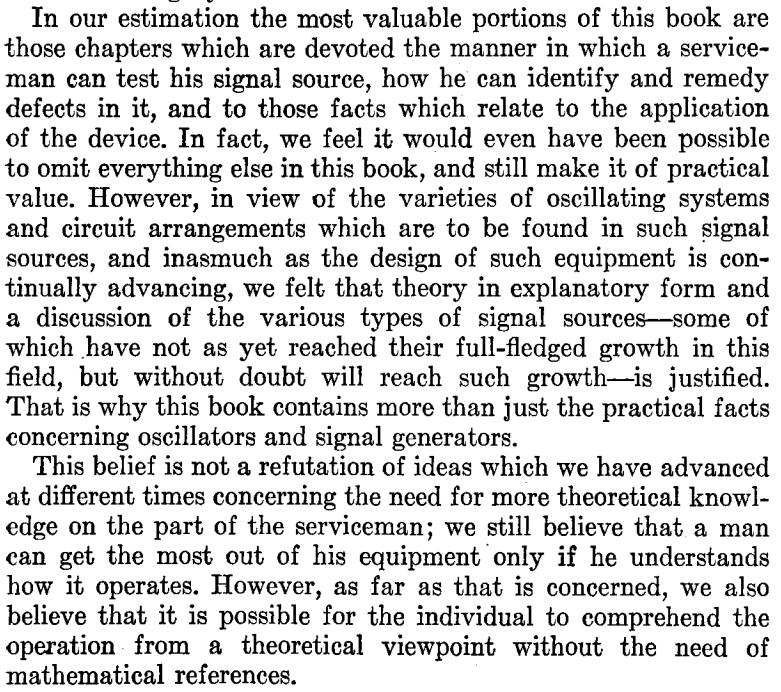
Thanks to Peter Parker VK3YE for alerting us to this wonderful 1940 book. John F. Rider -- a real hero of electronic literature -- does a great job in discussing the practical aspects of oscillator circuits.
This excerpt from Rider's foreword gives a sense of the approach taken in this book:
The book covers a lot of material. In addition to the standard oscillator circuits, he discussed multivibrators, relaxation oscillators and much more. There is a chapter on magnetostriction in which he shows that this property is the basis for crystal oscillators AND the mechanical filters that we are familiar with. In fact he seems to take what we would consider a mechanical filter and put it in the grid circuit of a tube to make an oscillator.
First, thanks to all who sent in suggestions. They came in literally from around the world, and this is a demonstration of the IBEW in action. I used or at least tried all of them. They were all good ideas.
Following Vasily Ivananeko's pseudonymous suggestion I rebuilt the carrier oscillator (apologies to G3YCC). I used the carrier oscillator/buffer circuit from Farhan's BITX20.
Henk PA0EME said I should look at the signal level at the input ports of the NE602 mixer. Henk was right --- the VXO input was far too high. I lowered it, but the problem persisted.
At first, I thought that the spur in question was so small that it would not show up on the air. I could not see it in the TX output using my TinySA spectrum analyzer. That was good news and bad news: Good that it was not showing up on the air, bad that I could not see it in the TinySA and use that image in the exorcism.
At first I thought that the spur was being caused by the 10th harmonic of the carrier oscillator and the third harmonic of the VXO. This seemed to fit. So, following VK3YE's sage advice, I built a little 69 MHz series LC trap (using a coil sent by AA1TJ, on a board CNC'd by Pete N6QW). That trap succeeded spectacularly in crushing the 10 harmonic. Look at these before and after shots on the TinySA:
Before Trap
After Trap
Spectacular right? But guess what? The problem was still there.
I scrutinized the situation once more. I realized that the spur would be more visible if I put the TinySA on the input of the transmitter's PA (a JBOT amp designed by Farhan) as opposed to putting it on the output. Watching the spur and the needed signal move in the TinySA as I tuned the VXO, I realized that they were moving in opposite directions. This indicated that the spur was the result of a carrier oscillator harmonic MINUS a VXO-generated frequency (as the VXO frequency increased, the spur frequency decreased). Looking at my EXCEL spread sheet, I could see it: 8th harmonic of the carrier oscillator MINUS the main output of the VXO.
To confirm this, I plugged the values into W7ZOI's Spurtune program. Yes, the spur popped up and moved as predicted.
For further confirmation I shut down the carrier oscillator by pulling the crystal from the socket, and then just clipped in a 5.176 MHz signal from my HP-8640B signal generator (thanks KB3SII and W2DAB). Boom! On the TinySA, the spur disappeared. Now I at least knew what the problem was: a harmonic from the carrier oscillator.
Following good troubleshooting practice, I turned off the gear and went to bed. When I woke up, an idea came to me: Before launching into a lot of filtering and shielding, just try running the carrier oscillator at a lower voltage, seeing if doing so might reduce the harmonic output. I disconnected the carrier oscillator board from the main supply and clipped in a variable voltage bench supply. Watching the signal on my TinySA, I watched as the spur completely disappeared as I reduced the voltage from around 13V to 10V (see video above). The main signal frequency level did not change much. I tested this by listening for the hated extra tones. They were gone. Exorcised.
Key lessons:
-- Spur problems are difficult to troubleshoot. Armstrong's superhet architecture is, of course, great, but this is definitely one of the pitfalls. Single conversion makes life easier. IF selection is very important. Choose wisely!
-- When looking at the TinySA as you tune the rig, pay attention to which way the spur is moving. This provides an important clue regarding the combination of harmonic you are dealing with.
-- The TinySA is a very useful tool. It seems like it is easier to use than the NanoVNA (which is also a fantastic tool).
-- It can be fun and rewarding to re-visit old projects. In the years between original construction and the re-look, new test gear has become available, and the skill and experience of the builder has improved. So problems that once seemed insurmountable become fix-able.
-- Thinking through a problem and thinking about possible solutions is very important. It pays to step away from the bench to think and rest. Rome wasn't built in a day. Here's a rough block diagram that I drew up (noodled!) while trying to figure out this problem:
Wow, I was really pleased to learn that Peter Parker VK3YE was a 2021 inductee into the QRP Hall of Fame.
This is a richly deserved honor. Peter Parker has been making extraordinary contributions to QRP and homebrewing for many years. I remember reaching out to him when I was just getting started with homebrew phone gear. I considered him a guru of DSB. He helped me a lot. Peter Parker was interviewed on the SolderSmoke podcast in 2013:
Peter has published many books and has produced many YouTube videos. He hosts an annual QRP gathering in his beloved home-town of Melbourne Australia that gets attention from solder-melters around the world.
Really simple, really nice. I like the innovative way they achieved the RF quadrature: they did it by splitting and phase-shifting the RF signal, not the VFO signal. I also like Peter's use of the AM broadcast signal to demonstrate the sideband suppression. Then, SSTV for icing on the cake.
You have long been one of the leading gurus on DSB. I remember absorbing all the info I could from your website when I was getting started in DSB back in 2001.
It's great that you found the article about DSB with inverted audio. It would be very cool to build a transmitter with the inverted audio, then confirm that it could be received with a direct conversion receiver without distortion.
The incompatibility of DSB TXs and DC RXs seems like a very cruel trick of nature. There are only a few people in the world who think about this, and most of them are in the comments section of your YouTube video! An elite group indeed.
Back in 2015 your review of a DSB rig got me thinking about this incompatibility: https://soldersmoke.blogspot.com/2015/07/peter-parker-reviews-dsb-kit-and.html
It is easy to see how a slight frequency difference between TX VFO and RX VFO would cause a lot of distortion, but similar distortion would be caused by a phase difference between the two VFOs. AM SW Broadcast receivers try to minimize the effects of fading by using an internal oscillator to replace the wavering carrier -- but they have to have it exactly on frequency and locked in phase with the distant station's carrier. I have a little Sony portable that has this "synchronous detection" circuitry. It is a complicated task and I don't think you could do it with the highly suppressed carriers of our rigs. Inverted sidebands to the rescue!
Thanks for the great video and all the tribal knowledge.
I think we should start calling these "Quarantine Rigs." Many of us are pulling off the shelves rigs that we started a while back but then put aside. Now, with the pandemic, we have the time (and the need!) to work on them. I like Peter's BITX receiver video, especially the part in the beginning where he wipes the grime and oxidation off the long-neglected copper-clad board. Follow Peter's lead: Pull those old projects off the shelf. Get them going. Now is the time. SITS! Melt solder and flatten the curve. Thanks Peter.
Each November, Peter Parker VK3YE and his ham colleagues from Melbourne share with us reports on Peter's annual "QRP by the Bay" event. I think VK3HN should seek a trademark for that hat. As soon as I saw it on the table in the video above, I knew these were Paul Taylor's rigs. FB Paul. Here is Paul's report: https://vk3hn.wordpress.com/2019/11/02/qrp-by-the-bay-chelsea-beach-melbourne-2nd-nov-2019/
9 December 2017 Santa Juliano Forest fires, snow storms, and an earthquake. Santa arrives from Hyderabad -- uBITX in the house. Radio history. First transtalantic amateur contacts. Bill's International Brotherhood Ceramic Discrete Direct Conversion Receiver Project. -- Goals -- Build your own receiver. Really. From scratch. No cheating. -- How to get started. Get parts and tools. -- Stage by stage. -- VFO first -- maybe build two. Bill built two already -- Nephew is testing the first one. -- Polyvaricon limitations. -- Varactor limitations -- Variable cap limitation. MEETING THE JULIANO STABILITY CRITERIA Understanding the F5LVG mixer Pete goes to the dark side with an SDR receiver. Pete's 800 Watt Amplifier gives him trouble. TRGHS. People in the News Cliff Stoll -- Still Passionate about Electronics Peter Parker -- VHF/UHF By the Bay Yardley Beers -- Early SSB with "The Black Rose" John Kraus -- Moonbounce without the Moon. MAILBAG
Be sure to read about Peter's ankle manacles -- he apparently uses them to get a good ground (sea) plane while running pedestrian mobile on the sea shore. Peter is DEDICATED!
I started off the build and both Bryan and Pete supported me along the way, thank you!
So here we have it:
The design slowly deviated further and further from the original, but I think I learned quite a lot by starting to make it “my own”.
The Arduino was changed to an UNO, yeah they are clunky and big, but I was not shooting for a pocket-size anyway… and they do have a proper USB port.
The RF-path is now switched by a relay straight after the filter, when the relay is relaxed the antenna is connected to the mixer, when I touch a paddle it connects to the TX circuit.
I have a short hang time from the last key input and it goes back to RX, VOX Delay I guess.
I completed the 700Hz bandpass filter, boy! this makes it a much nicer rig to work CW, I originally I skipped this filter for no good reason? That is the board standing up in the picture.
The TX circuit is a two stage, the first stage is a replica of VK3YE beach40 amplifier circuit, that also uses DB139. The second stage is a spin of the EMRFD Page 2.38 IRF511 Amp.
I have cranked it up to 17w, but it gets too hot too fast, as you can see I don’t have any proper cooling yet, I need to redo this board and plan for the heatsink a bit better.. it is now set around 10w, still getting hot, "599 TU 73”.
To be honest my CW does not go much further anyway, but I guess with this radio now completed I have one more reason to get my speed up.
I use for convenience both CLK0 and CLK1, when I go into TX I switch off CLK0 and do the keying on CLK1, both transmitter stages are powered up the whole time (until I stop keying as described above)
As the 700Hz filter worked so superb, I decided that I wanted to introduce “modes” to the rig, I can now switch the audio either thru the filters (CW) or straight to the AF amp (AM).
I do enjoy listening around, and we have a lot of AM stations on offer in my region.
I kept the smart RX mute transistor circuit and when I ask the Arduino to change mode, it will mute the receiver quickly, pull the relay and then un-mute again, no ear pain from the loud relay click. (I am happy with that detail).
The 2 line display became a four line, and I can change Tuning Rate, RIT, Key Speed and Mode by using only the encoder and the one button built into the encoder.
The front panel sports, on off, Headphones, Paddle and volume, the display and the big knob.
Power connector and USB Port on the side. I did complete the CAT control changes while working on this radio, it now uses the classic Kenwood interface e.g. TS480. (A lot fewer questions from the PC to answer.)
The CAT control works very nice while using N1MM, it works a lot less nice using CQRLog, I guess it has to do with the number of times the software in the PC is asking about things from the radio.
I will look into logic to only worry about incoming serial requests if I have not answered for some time, and never answer while in TX…
By pressing the VFO button a small arrow appears next to TR, if I push again it moves the arrow down to RIT and so on.
if I turn the knob with the arrow standing in front of e.g. KEY it will increase or decrease the KEY speed, when I press again, it will return to frequency control.
Oh, another detail (that I am happy with) while the arrow is in front of the KEY, you can fiddle with the paddle with out transmitting.. practical for testing the speed.
So this is a K4GC transceiver with bits and pieces from VK3YE and bits from the A65DC laboratory in Dubai, truly international.
To trim things in I scheduled a QSO with a local ham here, and things worked very nice, later the same night I made my first “DX” contact with RM2D!!! Moscow!!
What are the odds that a Swedish guy living in the UAE makes the first contact to another Swedish ham who lives in Russia!
Homebrew Hero Peter Parker has a new book on the market. I was really taken by his description of the joys of restoring older gear. Peter really nails it. Here is an excerpt:
Vintage Equipment
The collection, restoration and use of historical
equipment is another movement in amateur radio. The musty smell of
warming dust, the heavy clunk of rotary switches and the velvet smoothness of
precision tuning drives are joys of every use. Such sensuality is absent from modern
plastic-fronted, wobbly-knobbed transceivers. Old rig cabinets felt they
had something in them. A kick would hurt you more than them. And
etched panel markings confirmed they were built to last. Unlike today’s dainty push buttons with stunted
travel and disembodied beep, toggle switches showed you where they stood.
Weight, life and play made adjusting controls for nulls and peaks (as often
required) both a pleasure and occasional frustration. Even if only as
mechanical backlash on a bad tuning dial, it was as if the equipment was
telling you something, like a ridden horse does through its reins. Not
like newer gear’s lack of tactility which is like a ‘dead fish’ handshake, all
take and no give. There are psychic as well as physical joys.
The thrill of bringing neglected or dead equipment to life drives many.
It’s an underestimated skill. You start with nothing and almost anything
done represents progress when building from scratch. Whereas with a repair
it is very easy to render something that’s 80% good completely useless with a
careless drop or slip. More about ‘Getting back into Amateur Radio’ is at http://home.alphalink.com.au/~parkerp/gettingback.htm & the video at https://www.youtube.com/watch?v=g4ktP5K4x-I
Last weekend Homebrew Hero Peter Parker VK3YE hosted another of his amazing twice-yearly QRP events. It was at a park near the iconic Chelsea Pier in Melbourne. Peter Marks VK2TPM sent a very nice write-up with pictures: http://blog.marxy.org/2017/02/qrp-by-bay.html And a nice audio report: http://s3.marxy.org.s3.amazonaws.com/audio/QRP_By_the_Bay_2017.wav Peter Marks reports that most of the on-the-air activity was on the 120 foot ham band (40 meters for you modernists).Many BITX40's were on display.
Report from Pete on BITX 40 Session with California radio club.
Update on the BITX40 Module Revolution -- Check out the BITXHACKS page. Send in contributions. -- BITX20 mailing list very active. -- Raduino! -- Interview with Farhan with W5KUB -- Eliminating the commercial gear. -- BITX 40s on the beach in Australia. FB
Bench Reports:
Pete: -- Color Displays! -- KWM-4 -- OLED MADNESS!
Bill: -- Fixing up the old HT-37 HT37 to HT37 QSO with W1ZB -- Dabbling in VHF with Ramsey Aircraft band receiver. NOT FUN. -- Going all IC with Si5351 OLED NE602 rig. -- BANDSWEEP -- OLED Noise and the Active Decoupling solution.
Using LTSPICE as a diagnostic or understanding tool.
Of Waterfalls, Homebrew Rigs and Casual Critics on 40 meters. Words of Wisdom from W8JI.
LEXICON: HAYWIRE TOMBSTONE BIKESHEDDING from Todd K7TFC
Some great recent interviews by Eric 4Z1UG: Ian G3ROO Origins of ROO Regen at age 8 Hans Summers G0UPL Balloons! NO COMMECIAL GEAR David White WN5Y ELECTROLUMINESCENT RECEIVER EXPLAINED Rob Sherwood NC0B
MAILBAG:
Chris KD4PBJ's BITX 40 with improved stability Jerry W0PWE built a DIGITIA! Very nice. Worked Keith N6ORS and heard me! TRGHS Mike AB1YK's Al Fresco Scratch built BITX. But give that LC VFO another chance Mike! Steve N8NM 30 meter rig with salvaged CB LC VFO. FB Keith N6ORS Franken SDR rig with parts from the 1980s. FB SKN Bandscan from Mike WA6ARA I worked W1PID Jim! What is Mikele up to? Rocking Johannesburg and Kirghizstan via local repeaters: