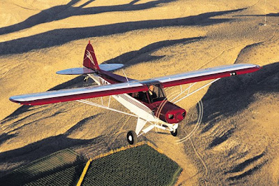
Podcasting since 2005! Listen to Latest SolderSmoke
Friday, March 13, 2009
G3ZJO: QRSS WIZARD!
Eddie has a lot of other tricks up his sleeve, including the use of a Voltage Controlled Variable Oscillator driven by a PIC chip for a very simple WSPR transmitter.
These and other inventions can be seen on Eddie's YouTube page:
http://www.youtube.com/user/g3zjo (most seem to be done without audio).
Also check out his QRSS Beacon web page:
http://www.g3zjo.talktalk.net/qrss.htm
Thanks Eddie
Wednesday, March 11, 2009
Heavens Above
On Monday, I'd noticed (via Blackberry) that my signal had disappeared from ON5EX's grabber. I could see a signal close to where I usually am, but it looked a bit different. On closer inspection I saw that EA6FNF had fired up a very nice 50 mw DFCW beacon on around 10140060 Hz. My signal was gone. When I got home I discovered a broken antenna wire. Once again, ON5EX and the internet had, in effect, relayed telemetry about the status of my QRSS system.
Fortunately I could fix this from the window -- no roof work was required. Skies were fairly clear on Wednesday morning, and as I looked up across the Janiculum Hill at Rome's pre-dawn sky, I saw a satellite going over from North to South. Of course, I wanted to know what I was looking at, so I turned to Chris Peat's very useful web site, Heavens Above. Very quickly, I was able to find out that it was either the Russian Okean O Rocket, or something called RADCAT.
Check out Heavens Above. Lots of great info on astronomy, satellites, and ham radio spacecraft:
http://www.heavens-above.com/
The antenna was quickly fixed. I should be back on the Belgian grabber now. It was a good ham radio morning in Rome. Thanks Jerry. Thanks Chris Peat.
Monday, March 9, 2009
KO7M's Two Cubs (Piper and MFJ)
KO7M has built his first QRP rig!
Well... I have been systematically listening to every soldersmoke episode from the beginning... Not a small task... :) I am currently up to episode 80, so I am closing in on the prize of being current.
BUT!! You have completely afflicted me with the need to build something... Most of my ham life however I have been mostly an appliance operator it seems though I built a lot of tube equipment in my younger years, burned a lot of fingers and once launched myself across the shack when I took hold of a 750 volt plate circuit.
Therefore, I am not up to the task of designing something from scratch, but ya know... I just HAD to build something and NOW, so I went with a kit. So, not exactly knack-ish but ya gotta start somewhere, eh?
I went with the little QRP transceiver from MFJ called the "MFJ Cub". I picked up a 40 metre version of this little gem, plugged in my MP3 player with my current episode of soldersmoke and started GENERATING solder smoke! This little kit went together very easily during moments when I had a few minutes to work on it.
Well, this evening (it is now 01:00 PST) I finished up with my last little bit of solder smoke generation and the little rig is done. Now for the REAL smoke test...
Since I don't have a current limiting power supply, I went with a little nine-volt battery for the smoke test. The little power LED lit up and I heard a pop in the headset, nothing was getting warm, so things looked good. We went to the full 12 volt supply and I went through the alignment process by first setting the product detector's operating frequency to fall within the CW filter passband. I then used my Icom receiver to set the VFO operating range since I don't have a frequency counter. I then peaked the receiver bandpass filter for best sensitivity and lastly set the BFO to the correct sideband.
For the transmitter, I first set the carrier offset to about 600 hz from the received signal and peaked the transmitter bandpass filter for maximum RF output. I only have a simple SWR bridge for indicating a relative output level forward and reverse. Lastly, I set the power output level to about what I estimate should be about one watt.
Whoo hoo! Pulled off the dummy load and plugged in the G5RV and antenna tuner and started tuning around the low end of 40 metres and there were signals everywhere. Nice receiver in this rig. The tuning is a little fast, but managable. Seems to be very sensitive. I happened to catch the end of a CQ call as I was scanning around the band and when he signed I gave him a call.
To my complete surprise, he came back to me and gave me a 459 report... From Japan! I bagged a JA1 on my first QSO on a rig I built myself (or at least assembled). There is nothing better, I tell ya! I attached a screen shot of the Solar Flux level for my first QSO.
So... I am afraid to say you have reinstilled the need to melt solder in me after an absence of over 30 years. It is a disease I tell ya! I have located copies of both Solid State Design and Experimental Methods, which are both on the way and I am eagerly looking forward to figuring out what the next project will be.
The knack is returning...
Kind regards,
Jeff Whitlatch - ko7m
The Kettering Group: Satellite Pioneers
More info here: http://www.svengrahn.pp.se/trackind/trackin1.htm#KEttrack
Sunday, March 8, 2009
Clockwork CW: The Path to Minimalist QRSS?
Well, maybe not using that one. But something like it. The idea -- mentioned recently on the podcast -- is to use a mechanical clock mechanism to generate the CW for a QRSS beacon. This would allow us to get the transistor count for our beacon down to one. For some odd reason, some of us find this appealing, especially when you consider that the transistor count on the receive side is in the tens or hundreds of millions. One is the magic number. You can see how this project brings together two of the biggest littlest recent trends in the QRP radio: QRSS and minimalist radio.
It's kind of scary when you Google something and are referred back to your own blog. That's what happened to me on this subject. Back on May 28, 2008, this was posted (by me!) as a comment to one of the beacon-related posts:
Hello Bill and Others:
A few years ago, a buddy had made a neat keying operation made by taking a
one RPM clock motor and had it rotate a printed circuit board disk that had
the callsign etched on it several times sequentially. Clock motors are
made to run continuously for years, and it stood up with just an
occaisional cleaning of the wiper arm with spray cleaner.
All the best to all!
73 de Lee Smith VE4ANC
This message from Lee was a response to a January 1999 question from me. So we are sort of re-inventing the wheel here.
Of course, there are some QRSS beacon circuits out there with VERY low transistor counts. Hans Summers has one on his site that used a bi-stable multivibrator to generate a pattern for QRSS. That would yield a total transistor count of 2 or 3. But we are going for one single transistor. And I kind think we should look for something that will allow for the transmission of callsigns.
Here's an e-mail exchange from the Knights of QRSS mailing list that may generate some ideas:
Re: [Knightsqrss] Junkbox + soldersmoke = pattern generator
Very nice idea Bill. After tiny solar mepts this could been our next QRPP/ET challenge .
73 de Paolo IZ1KXQ
--------- Initial Header -----------
From : knightsqrss-bounces@cnts.be
To : knightsqrss@cnts.be,"Soeren Straarup" xride@x12.dk
Date : Fri, 6 Mar 2009 21:48:55 -0800 (PST)
Subject : Re: [Knightsqrss] Junkbox + soldersmoke = pattern generator
It would be fun if the clock were a "wind up" type. And for extra credit: Power the transmitter with the energy from the same spring mechanism (or other wind-up device) that powers the clock!
ET PHONE HOME!
--- On Fri, 3/6/09, Soeren Straarup <xride@x12.dk> wrote:
From: Soeren Straarup <xride@x12.dk>
Subject: [Knightsqrss] Junkbox + soldersmoke = pattern generator
To: knightsqrss@cnts.be
Date: Friday, March 6, 2009, 3:30 PM
Hi list,
Hans Summers has made an astable multivibrator as pattern
generator.
Bill Meara has thought about making a analog clock.
Alan Yates loves my idea of an exercise bike pattern
generator.
Though i'm open for suggestions. No pics, pc or
any other programmable
devices.
Rules of design:
1) KISS
2) Should be in most junk boxes
3) Pattern should be easily changed (diversity, more
homebrewers)
4) KISS
This is for a simple Pixie2 TX modified to be a QRSs TX.
Stability? SSShhh.
Vy 73 de OZ2DAK
Soeren Straarup | aka OZ2DAK aka Xride
Friday, March 6, 2009
Lots of Great Old Radio Books FREE!
http://tinyurl.com/cvc4qd
That link led me to Project Gutenberg where I plugged in the word "radio" and was instantly given a list of really nice old books, including the Radio Amateur's Handbook by A. Frederick Collins of Congers N.Y. (my home town). Here it is:
http://www.archive.org/details/theradioamateurs06935gut
Thanks Greg!
Wednesday, March 4, 2009
Italians at the Forefront of QRSS
Born in 1944, in Lucca, Tuscany, Italy. Got a Doctorate Degree in Physics at the University of Pisa. Since then worked for IBM, with various responsibilities. Radioamateur since 1966, active on most bands, from 160m to 23cm. Lately experimenting with 137 kHz, recently allowed in Italy with 1W ERP.
Studying and applying DSP and digital techniques in general. Author of Winrad, SDRadio, Spectran, Jason, Argo and Hamview, widely diffused programs for SDR (Software Defined Radio), spectral analysis and real time filtering of audio signals, received with a radio and routed to a PC equipped with a soundcard.
Despite the age, open to learn new techniques and theories. *Not* a tube (or valve, depending on the side of pond you are reading this) nostalgic.
73 Alberto, I2PHD
Home page http://www.weaksignals.com