Podcasting since 2005! Listen to Latest SolderSmoke

Thursday, February 9, 2017

VK2EMU's Biscuit-Tin Direct Conversion Receiver


Bill and Pete:
First Sound

The enclosure came first, then the radio. The Homebrew challenge - build something in a Christmas Biscuit tin - only one rule, no mains power.

Step one - eat the contents.

VK2WI is an Australian version of W1AW and transmits weekly new bulletins on a number of bands from 160m to 23cm. On 80m the frequency is 3595kHz, so let's build a DC receiver for that.

I used a 7190kHz crystal, divided by 2 with a 74HC74 to get 3595kHz. The rest of the radio is pretty standard - double tuned front end, NE612 mixer, followed by a TL071 and a LM386. The reduction drive on the tuning cap gives a band spread of about +/- 300Hz.


The boards are all 2 inch x 2 inch and made on a PCB mill that I was given a few years ago. 

There should be enough room in the bottom of the tin a pack of 8 C cells to make the radio truly portable. Next step is to fit an audio low pass filter.

It is a pleasure to sit on the rear porch and listen to the Sunday night broadcast on a home brewed radio, while eating the contents of another identical tin - I wonder what I will do with that one?

73  Peter VK2EMU


Wednesday, February 8, 2017

VK3YE's GREAT "QRP by the Bay" Event

Last weekend Homebrew Hero Peter Parker VK3YE hosted another of his amazing twice-yearly QRP events.  It was at a park near the iconic Chelsea Pier in Melbourne.   Peter Marks VK2TPM sent a very nice write-up with pictures:

http://blog.marxy.org/2017/02/qrp-by-bay.html

And a nice audio report:

http://s3.marxy.org.s3.amazonaws.com/audio/QRP_By_the_Bay_2017.wav

Peter Marks reports that most of the on-the-air activity was on the 120 foot ham band (40 meters for you modernists).  Many BITX40's were on display.


Tuesday, February 7, 2017

ZL1UEM'S Tiny OLED Si5351 Arduino VFO


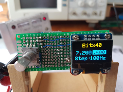
Hugh ZL1UEM has come up with a very creative way to take maximum advantage of the small size of the Si5351 board, the Arduino, and the OLED display.  He even has the rotary encoder in there.  Look carefully -- he uses both sides of the board.  Very nice. Thanks Hugh!

Hi Bill,

First let me say that I have been an avid follower of the SS blog and podcasts since the days of your podcasts involving Mike KL7R.

Like many others I was tempted to purchase the $49 surface mount module from HF Signals.  As a keen home brewer I felt guilty about employing a prebuilt board but excused my decision on the grounds that I would build a DDS and other accessories myself.

In addition to follow the SS blog I also check Pete's blog regularly and was excited by his OLED VFO for the Bitx40.

I constructed it on a small double sided matrix board with plated through holes.  A bit of noodling led to the layout shown in the photos.  There is only one board with components mounted on both sides.  The board came to life on the first power up but the text spilled off the bottom of the display.

I assumed that the sketch that I had downloaded from Pete's blog was for a different OLED module.  I knew that he had also used a yellow/blue OLED, the same as mine, previously so emailed him requesting a sketch for this OLED.

I was taken aback when he informed me that the sketch I had was the same for both the dual colour OLED and the black and white one too.  Pete suggested that I swot up on the use of OLEDs generally and that perhaps I should first experiment with the text size to begin with.  He also offered some advice about the mapping of the screen.

I soon discovered that the text size was not the cause of my grief and that I needed to look elsewhere.

I first tried running the ssd1306_128x64_I2c sketch from the sample sketch folder and was rewarded with the message "Height incorrect, please fix Adafruit _SSD1306.h".  A search of the Internet revealed that I needed to edit the .h file and find "#define SSD1306_128_64" which was commented out and uncomment it and make sure that the other two options, _32 and _16, were commented out.

My next problem was how to edit the specified .h file.  I tried notepad but the text all ran together.  Another internet search revealed that Notepad++ was a suitable choice and it did indeed cut the mustard.

A reload of the sketch completely restored the display to full functionality.

All this may be obvious to many but it was all new to me and if I had not been prompted by Pete l would not have had learnt so much and would not have had the same sense of achievement when it all came together.

Many thanks to you and Pete for providing a focus for my hobby.

73's
Hugh ZL1UEM

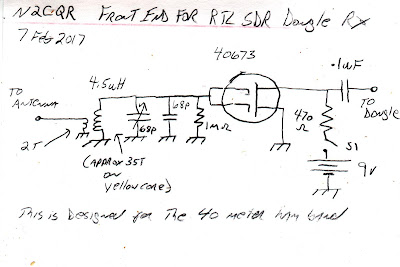
Schematic for the RTL SDR Dongle Front End

Here it is.  Very simple.   I used an obsolete 40673 dual gate MOSFET.  I didn't need both gates so I just soldered them together. You could probably substitute an easily obtained MPF-102  JFET.  The capacitors and the coil in in the gate circuit form a parallel LC filter circuit that resonates in the 40 meter ham band.   The 1 Megohm resistor maintains a very high impedance for the LC circuit, helping to maintain circuit Q (sharp response).  It also drains off any charge that builds up on the gates.  For the antenna input I just put 2 turns on the 4.5uH coil -- this too helps maintain LC filter response.  The 470 ohm resistor serves as the load and limits quiescent current through the MOSFET.  It should pull about 19 milliamps -- with a 9V battery that should give you around 26 hours of listening time between battery changes.  That's fine with me -- I don't use this thing that much. 

Realize that I'm using this with an RTL-SDR dongle that has been given the familiar modification that allows it to use direct sampling in the HF bands.   Some ideas here:
and here
and here


Monday, February 6, 2017

Adding a Homebrew Front End to an RTL-SDR HDSDR Receiver

I started playing with the RTL SDR dongles again.  I wanted to use them to confirm that my BITX signal is NOT 9 kc wide (it is not).  I also wanted to try to confirm the aircraft band frequencies in use in this area.

So I got the HDSDR software running and plugged in the dongle that I had modified for HF use.  It worked great, but I could see (literally SEE) that it needed some bandpass filtering and perhaps a bit of RF gain.  So today I threw together this device.  Dual gate MOSFET (gates tied together) with an LC filter on the gate.  Power from Malaysia via the 9V battery.

It works great. It was fun to add a bit of homebrew to an otherwise soul-less commercial receiver.   But beware: that waterfall is addictive, even for a hardcore Hardware Defined Radio guy like me.
Designer: Douglas Bowman | Dimodifikasi oleh Abdul Munir Original Posting Rounders 3 Column