Podcasting since 2005! Listen to Latest SolderSmoke

Monday, July 15, 2019

The "Fish Soup 10" Homebrew QRP CW Transceiver


The box with the two grey knobs on the left is the Herring Aid 5, the receiver that took me 38 years to complete. The box on the right is a VFO I originally built for my first BITX40Module -- it started out around 4 Mhz but I pulled turns off the coil until it was in the 40M CW band.  The Altoids in near center has the buffers -- a 40673 MOSFET and a 2n3904 BJT. The box in the back holds the Tuna Tin 2.  There the oscillator has been reconfigured as an amp.  A relay switches the output from the buffers between the receiver and the transmitter.  That big switch in the center switches the antenna and the 12 V for T/R.  The circular black thing is piezo buzzer used for CW sidetone -- I have it glued to the board upside down to keep the volume down. 

The whole thing is mounted on a kitchen cutting board.  A breadboard! 

The most difficult part of all this was getting the needed 800 Hz drop in TX freq on transmit.  You need to do this with a rig like this or else you won't be in the other fellow's passband.  I did a lot of cut and try -- in the end I put a 5 pf cap across the coupling cap from VFO to buffer.  This 5 pf cap switches in on transmit via a small relay.   It works.  I just spoke to N8AFT out in Columbus, Ohio and I was in his passband.  

So five transistors in the receiver, two in the transmitter and three in the VFO/Buffer. So it is the  Fish Soup 10.  

It puts out about half a watt.  On CW.   I am feeling virtuous and vaguely superior. I've made several more contacts.  It all works very well and is a lot of fun. 


Sunday, July 14, 2019

Feedback on QSOs -- Listeners are Listening

On opposite coasts and with rigs at opposite ends of the technology spectrum, Pete and I have been putting new homebrew rigs on the air.  I'm working on a QRPp transceiver using 10 transistors.  Pete is working on an SDR rig that must use, what?,  thousands or millions of transistors.  

We've both been getting nice feedback, often from SolderSmoke podcast listeners.  Above you can see my 8 July notes on a contact with K3QP.   I was running about 1/2 watt, crystal control, from the Fish Soup 7 combo rig. 

---------------------------------
In an earlier post I mentioned Pete's success in working coast-to-coast on 40 SSB with his homebrew SDR RADIG.  Turns out that someone in St. Louis heard the contact: 

From: Steve 
Sent: Saturday, July 13, 2019 6:16 PM
To: Pete
Subject: Friday QSO

Hi Pete

Heard your QSO to Virginia last evening. Conditions were rough but could hear good enough. I’m located west of St Louis and was outside portable with KX2 and wires tossed in a couple trees. Tried to tail end but of course my signal was not good for you in California.

I really am amazed at the work you put into your projects, websites, and podcast. Can’t thank you enough. Please keep it up.

I worked at McAir in St Louis and spent many hours in the MDEC building St Charles. That was in the late 80s.

Steve
K0SAM
----------------------------------

Finally, earlier in July I had a contact with K1PUG.   Someone north of the border heard us: 

On Sunday, July 7, 2019, 01:17:47 PM EDT, Dave  wrote:

I heard your QSO with Hank K1PUG at my cottage in Canada (FN15ac) this morning. I wondered why you were so faint (since I had been getting good reports with 5W into your area) but when I read this morning’s entry in SolderSmoke, and saw you were 750mW, all became clear.

73,
Dave KM6CPF / VA3NIA

Saturday, July 13, 2019

N6QW goes Coast-to-Coast with HB SDR RADIG


From: Frank
Sent: Saturday, July 13, 2019 6:55 AM
To: Pete Juliano
Subject: Re: 40M QSO with N6QW

GM Pete 

Yes fun QSO last night. You did have a great signal and excellent audio from your HB SDR .

Lots of great info on your website. 

I am enjoying my wire beams.  I have two five element wire beams mounted end to end beaming Europe that I get on that direction a lot. I'm planning to get an Array Solutions StackMatch soon that will help my signal even more.

Keep up the good work with the SDR rigs Pete.
I look forward to our next QSO. 

73

Frank WA3RSL 

On Jul 13, 2019 9:42 AM, "Pete Juliano" wrote: 
Hi Frank,

Last night was the first coast to coast QSO with my homebrew SDR Transceiver. Thanks for the signal report and the comments on the signal.

This has been a fun project and my main band of operation these days is 40M. I have the capability to put the SDR on 75 as well as 20M. The second prototype (now in work) will use plug in coils for those two bands. It is simply amazing what can be done with a $35  computer.

I have several websites but one has been dedicated to SDR and there is more documentation about the SDR project.


Thanks again and at times you hit 15/9. Nice radio and nice antennas.

73’s
Pete N6QW

Monday, July 8, 2019

Chinese Micro-Satellite Photographs Eclipse -- FROM THE MOON


Back in October 2018 I posted about this Chinese satellite: 
According to report by Xinhua, a microsatellite developed by the Harbin Institute of Technology in northeast China's Heilongjiang Province, which is now orbiting the moon, captured mesmerizing photos of Earth during the solar eclipse in the early hours of Wednesday (Beijing time).
It is to be noted that the microsatellite, weighing 47 kg and named Longjiang-2, was sent into space on May 21 last year, along with the Chang'e-4 lunar probe's relay satellite dubbed as "Queqiao" and entered lunar orbit four days later.
According to the research team from the Harbin Institute of Technology, the microsatellite carries a mini CMOS camera that only weighs 20 grams, which makes it easy to operate, and it can take pictures at short intervals.
“Since the camera uses an automatic exposure mode, the camera's field of vision must contain a certain area of the moon to realize correct exposure. When the recent total solar eclipse occurred, the orbiter was flying over the far side of the moon. In the few minutes before and after the moon blocked the earth, all the conditions were right to take the pictures,” Xinhua further quoted the team as saying.
According to the team, to avoid becoming space rubbish, the microsatellite will be controlled to crash into the moon after it stops operation at the end of July.
As per Xinhua, the team cooperated with amateur radio operators in Spain and Germany in taking and receiving the photos. Nearly two pictures taken by the microsatellite during the solar eclipse were sent back to Earth on Wednesday. 


Sunday, July 7, 2019

The Fish Soup 7 QRP Rig -- On the Air on 40 Meters (video)


I don't know why, but this weekend I got the urge to get on the air with a very low power homebrew QRP rig.   I reached for my Tuna Tin 2 -- Herring Aid 5 combo.  I call it the Fish Soup 7 (seven transistors in total). 

I first tried to turn this rig into a transceiver by taking the VFO signal from the receiver (it is direct conversion) and using it to excite the Tuna Tin 2, but it just didn't work out.  The oscillator in the Herring Air 5 is very bare bones -- no buffering and an LC circuit that is mostly L (10 uH).  It became very difficult to get a stable amount of CW offset.  So I went back to crystal control for the transmitter.  I did replace the 5K tuning pot in the RX with a 10k 10 turn pot (thanks to W8NSA).  Tuning is now very smooth.  I used my old UK freq counter to monitor my receive freq. (Thanks to Tony Fishpool G4WIF-- back in 2009 he sent me the CMOS chip that brought this counter back to life.) 

I was putting out about 750 milliwatts.  

I had a very quick contest-like contact with K2D -- one of the "13 Colony" stations.  Then a longer chat with Hank K1PUG (see video above).  

I had lost my 7050 crystal, but this morning it re-appeared.  TRGHS. 

As you can see in the video I am using the beautiful VU3XVR  key that Farhan brought me from India. 

This was fun.   I may try to put a VFO of some sort into the TT2, just to get more agility.  But I want to keep things simple.  

Look for me on 7050.  

Wednesday, July 3, 2019

Building Spark-Gap Transmitters -- And a Very Cool Coherer (video)


The creators of "Plasma" and "Blueprint" YouTube channels have collaborated on this very interesting video about spark-gap radio transmitters and receivers. Really nice work.  Especially impressive was the coherer build by Blueprint.  I detect the spirit of Nikola Tesla in his lab!  

Tuesday, July 2, 2019

LightSail 2 -- Solar Sailing Cubesat with a Beacon on the 70cm Band


Once deployed, LightSail 2 will automatically transmit a beacon packet every few seconds, which can be decoded into 238 lines of text telemetry describing the spacecraft's health and status, including everything from battery status to solar sail deployment motor state. Every 45 seconds, the spacecraft will transmit "LS2" on the spacecraft's frequency of 437.025 MHz, within the Amateur Radio 70-centimeter band.
Further details can be found online at,
http://www.planetary.org/explore/projects/lightsail-solar-sailing/ 


Saturday, June 29, 2019

Caption (or meme) Contest!


Please supply a caption for this picture.  Or turn it into a meme.  

Place submissions in the comments section below (or e-mail them in) 

Feel free to use the hosts of the SolderSmoke podcast. 

Antuino's Cubesat Origins, and How it Works (with video)


In a series of e-mails to the BITX20.io group, Ashhar Farhan VU2ESE provided background information on the origins of his new "RF Lab in a Box' -- the Antuino. He also explained how the device performs the SWR meter, Power Meter and  Scalar Network Analyzer functions.  

Farhan's Antuino Page: http://www.hfsignals.com/index.php/antuino/

Dec 27, 2018 to BITX.io

peeps,


while trying to measure the swr on the cubesats, i figured i couldnt use any of the analyzers i had access to. they were simply too big to be stuffed inside a 10 cm cube. my simple resistive bridge was too insensitive for any reasonable work. so, i sat down and made an antenna analyzer from a spare raduino. 

the code is wobbly and just about enough to get my work done. it works on a superhet principle. this is not my clever idea, rahul had mentioned this approach taken by a russian builder. i havent seen the original design. it would be interesting if rahul or someone can point me in the right direction.

the code and a pdf of the circuit is on https://github.com/afarhan/antuino. i am attaching the circuit for the lazy bones.

have a great holiday and get some dx !!

- f

Dec 28 2018

Jerry,

first, thanks. there is substantially your code in there.

second, onto the circuit. it uses two clocks. not three. the third is a spare output. more on that later.

the circuit here uses a resistive return loss bridge. the clock 1 drives the bridge through the R22 to a low level of -10dbm. If the bridge is perfectly balanced (that is, the antenna, R21, R29, R16, all the four are the same ohms), then, there will be no RF developed across pins 3 and 4 of the ADE mixer. Under ideal match conditions, there is no RF across the R26. As the mismatch increases, so does the RF across R26. 

We could directly detect the voltage across the R26 with a diode detector. This is quite a popular configuration with most of the simple resistive kind of SWR bridges (like the one designed by Dan Tayloe). This simplicity comes at a cost. The problem is that the detector responds to all the RF between the arms. For instance, if another ham down the block starts to transmit, that energy will show up across the R26 and you will get crazy SWR. I had that problem with broadcast FM showing up on my 7 MHz dipole! Even if there was no RFI from elsewhere, harmonics and spurs from your own transmission can show false readings. 

Here is an example: a 7 MHz transmitter with a 14 Mhz harmonic that is 20 db down is connected to a 7 MHz dipole. The dipole is perfectly tuned to show 1:1 SWR, hence, it should show no RF across R26. However, as the antenna is reflecting back the 14 MHz energy, the 14 MHz shows up across the R26.

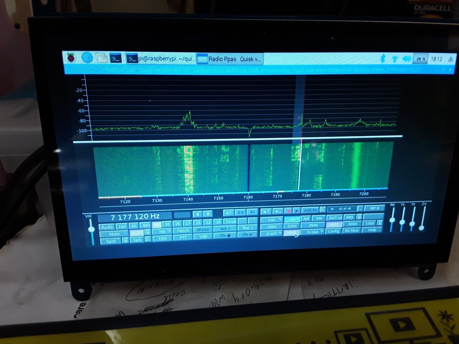
What's the solution to get a clean dip?The solution is to substitute a simple detector like a diode detector with a simple receiver that is tuned exactly to the frequency that you want to measure the antenna at.

So, the ADE-1 mixer, Q2, Q1 together form a very simple superhet receiver with 25 MHz IF andCLK2 as the local oscillator. The RF at the IF is directly detected and converted to db range with the AD8307. This simple configuration makes this a very powerful instrument.

Here are things you can do with it:

1. Switch off the CLK1, now you have a receiver that can very accurately measure RF levels at any specific frequency in db range. For instance, you connected your transmitter with a suitable RF attenuator to P3, you can tune to various harmonics and measure them very accurately. If you inject a two tone signal into an amplifier, you could easily measure the IMD and IIP3. 
2. With the CLK1 on, the instrument now measures the return loss. you can measure the SWR of an antenna, S11 parameters of an amplifier, filter, etc.
3. With CLK1 off, CLK 2 on, the CLK2 can now tune to the frequency tuned in by the receiver's LO (CLK0). By connecting a device/filter between P3 and P4, you can sweep it to measure the gain, frequency reponse.
4. As the diode mixer (ADE-1) has harmonic response, a local oscillator at 135 MHz, will also convert a 430 MHz signal into 25 MHz IF (430 - (135 x 3)). This is possible because we are driving the diode mixer with a square wave from the Si5351 and the local oscillator at 135 MHz also has a 405 Mhz harmonic in it. Hence, the range of this instrument extends to UHF.

The ADE-1 mixer is quite similar to the ubitx mixers. You could even use ubitx kind of discrete version of a diode mixer, it doesn't work too well beyond 50 MHz. The pins 4 and 3 of the ADE-1 are the primary winding of the RF-input side transformer. The documentation recommends that we must ground 4, but that is not essential. We need a differential drive between those two pins, that is what the bridge provides anyway. 

73, f

jerry,

i built it so i could stuff it inside the cubesat to measure the antenna. an external spectrum analyzer and its cables were upsetting the RF model hence, i needed something that could read the return loss sitting inside the cubesat. then, i borrowed by daughter's DSLR with a monsterous tele lens and sat 100 meters away to read the the LCD display as it swept through the range. 
the analyzer was removed once we knew the correct dimensions and the actual payload went inside the bird.
- f

Designer: Douglas Bowman | Dimodifikasi oleh Abdul Munir Original Posting Rounders 3 Column