Just go to http://soldersmoke.com. On that archive page, just click on the blue hyperlinks and your audio player should play that episode.
http://soldersmoke.com
Here's how I started with the Elsie program. Note that to get a 50 ohm match on both ends it needs an impractically low value for the coils (.064 uH).
But Elsie lets you specify the coil value. So I then I went with 1 uH. But with this value you don't get 50 ohms at either end. You need a matching network. Elsie provides this too!
I asked Elsie to match my BP filter to 50 ohms. It provided several options to do this -- I went with a simple capacitive impedance divider. But alas, I was now bumping up against the 7 limit of the free version of Elsie so I had to reduce the number of LC elements from 4 to 3. Bummer.
With 3 LC tuned circuits and matched to 50 ohms the plot looks OK. But I would have preferred 4 LC circuits.
The rftools website created a BP filter for me with 4 LC elements, and matched to 50 ohms. Very useful. https://rf-tools.com/lc-filter/
But here's my problem: With both the filter designed by Elsie and the one designed by rftools, I found that the filter passband was too low. It was in the 12 - 13 MHz range. I found that by removing 3 turns from the 1 uH coils I could move the passband up to the desired range. But why the discrepancy? I was measuring the coils and the caps with an AADE meter. I was testing the passband both with a NanoVNA and with a combination of an HP8640B sig gen and a Rigol oscilloscope (with the filter terminated into a 50 ohm resistor). Any suggestions on why these filters should have passbands lower than predicted would be appreciated.
This receiver required almost no coaxing or tweaking, probably because I had been so careful about testing and measuring each of the stages.
I have been pleasantly surprised at how well the receiver works without an RF amplifier ahead of the first mixer. But I need to know how much AF gain I have in order to understand how/why the entire receiver works so well. I think I have about 35 db of gain (combined) through the two TIAs and the crystal filter. That would mean that all of the remaining gain is provided by the AF amplifiers (with some loss in the product detector). I haven't really measured the gain of the AF preamp/LM386 combo, and I had some trouble measuring the input impedance of the pre-amp with the NanoVNA.
The 75 meter LC filter to the left of the VFO is actually a bandpass filter, not the lowpass filter. And what I call "the mixer" to the right of the VFO is really the Product Detector/BFO.
For the 75 meter bandpass filter, I used the ELSIE program.
75 meter Bandpass Filter designed in Elsie. 10 turns on a T50-2 toroid yield .46uH.
Here's the plot from Elsie on the 75 meter BP filter.
Alan W2AEW asked for a picture of the VFO output.
On this shot I had the probe between theVFO and the
outboard booster amp that I built to bring it to 7dbm.
This is a 5.2 MHz crystal filter. I used the G3UUR method for determining the crystal's motional parameters. I then used Dishal and AADE software to design a 10 pole Cohn Min-Loss filter. I tested the bandwidth with an Antuino Scalar Network analyzer (thanks Farhan!) and a NanoVNA. I found the passband to be a bit tight for SSB, so I replaced the capacitors with caps of a slightly lower value -- this broadened the passband. It is still a bit tight, but the SSB audio -- while not enhanced or Hi-Fi -- sounds fine.
Passband filter shape as seen in the Antuino and in the NanoVNA. The -20 db line in the Antuino actually corresponds to no loss.
The schematic provided by the AADE software. Dishal software may have come up with better, more correct values for the capacitors.
The passband as predicted by AADE. Skirts so nearly vertical as to strike fear in the hearts of SDR owners!
Filter under construction -- waiting for the caps from Mouser.
First scan with the NanoVNA. Insertion loss looks very high but that is only because I am terminating the filter with resistors -- I just wanted to see the passband shape.
I continue to work on the "Mythbuster" rig, but I am taking it slow, trying to learn something from each stage. I'm especially trying to master the used of the great test gear that has arrived in my shack in recent years: The Antuino, the NanoVNA, and the TinySA.
Above you can see the passband of the 10 pole crystal filter as measured across the 50 ohm terminations on the filter. I use simple FT37-43 transformers to match the filter impedance down to 50 ohms. I used the Antuino first -- it scanned the passband and held the image on its screen. I then disconnected the Antuino and connected the NanoVNA. So in this shot you can see the passband on both devices.
You will notice that the Antuino says there is a 20db insertion loss. That's only because in the Antuino 20db is really 0 db loss. I think the NanoVNA gives a more accurate insertion loss reading -- about 3-5 db. The cool thing is how similar the shapes of the passband are.
As explained in the video, in the course of using my RTL-SDR dongle I noticed that the signal being put out by my Hodgepodge rig had some problems. There was poor opposite sideband rejection, and in terms of audio quality I has putting out too many lows and too few highs. I figured the problem was the result of the carrier oscillator frequency being a bit too low, a bit too close to the flat portion of the crystal filter passband. I needed to move that carrier oscillator frequency up a bit.
BITX40 Module BFO
In the actual BITX40 Modules, L5 was replaced by just a jumper wire, and the C103 trimmer was not on the board. Farhan and his team instead selected X5 crystals to match the passband of the 12 MHz crystal filter. Mine was originally at 11.998653 MHz. But I wanted to tweak mine a bit -- I wanted to move it up about 500 Hz. Reducing the capacitance would move the frequency up. Putting capacitance in series with C102 would have the effect of reducing the capacitance in the circuit. I just removed the jumper wire and used the holes for L5. First I put in a single 30pf capacitor. This dropped the capacitance between X5 and ground to 18 pf. That resulted in too large a shift. So I added another 30 pf cap in parallel with the first one. This resulted in a total capacitance from X5 to ground of 26 pf. This was about right -- the carrier oscillator/BFO frequency was now 11.9991 Mhz. I had moved the carrier oscillator frequency up by 447 Hz -- just about what I was hoping for.
This was a very satisfying fix. it was a chance to put to use experience with other SSB rigs, to make use of the RTL-SDR dongle as a diagnostic tool, and to tinker with the BITX40 Module in the way that Farhan had intended for it to be tinkered with.
I'd done this kind of adjustment before, but without the benefit of an SDR display. Below is the story of one such adjustment.
---------------------------------
A Flashback to 2001-2002
(From my book "SolderSmoke -- Global Adventures in Wireless Electronics")
Now it was time for some debugging and
fine tuning. I needed to make sure that
the frequency of the carrier oscillator was in the right spot relative to the
passband of the crystal filter. If it
was set too high, the filter would be chopping off high notes in my voice that
were needed for communications clarity, and it would allow too much of what
remained of the carrier (residuals from the balance modulator) through. If it
was set too low, the voice signal transmitted would be lacking needed base
notes. I didn’t have the test gear
needed to perform this adjustment properly, but my friend Rolf, SM4FQW, up in Sweden
came to my aid.
One night, during a conversation with
Rolf, I explained my problem and he offered to help me make the adjustments… by
ear. Performing an electronic version of
open-heart surgery, with power on and Rolf on frequency, I opened the case of
the new transmitter. The carrier
oscillator has a small capacitor that allows the frequency of the crystal to be
moved slightly. With Rolf listening
carefully, I would take my screwdriver and give that little capacitor a quarter
turn to the right. “Better or worse?” I
would ask.
I think this little adjustment session
captures much of the allure of ham radio.
There I was, out in the North Atlantic,
late at night hunched over a transmitter that had been forged from old Swans
and Heathkits, from cell phone chips, and from bits of design from distant
members of the fraternity of solder smoke.
Pericles, the source of many of the key
parts, was gone. So was Frank Lee, the amateur whose SPRAT article had inspired the project. But Rolf and I carried on with the core
tradition of the radio fraternity: hams help their fellow hams overcome
technical difficulties.
My radio emotions were swinging wildly as I watched this video.
Readers may recall that over the years I have brutally cannibalized several QF-1s. I was enticed into doing this precisely by the tuning cap that the videographer so alluringly describes. It has a built in 7:1 reduction drive! How could I resist? These wonderful caps live on in several of my homebrew rigs.
I also put the conveniently sized metal cabinets to good use -- one holds frequency counters for my AM station, the other houses an Si5351 VFO/BFO that can be used with many rigs.
After extracting the cap and putting the boxes to good use, I was left with the remainder of the circuitry. I recently put even this stuff to use by using the coils to make a triple LC circuit filter for 455 kHz. This may someday be used in a receiver. So you see, I've not been wasteful.
And the thing only cost 9 bucks back in the day... So I didn't really do anything bad. And besides, adding a regen circuit to a superhet is kind of backwards, right?
But then the video producer started talking about how nice his QF-1 looks, even after more than 60 years. And about how much it improved the performance of his AR-1. And then, the kicker: He said the QF-1s are now "relatively rare."
I hang my head in shame. I am a serial QF-1 killer. And I don't know if I can stop.
Mars is moving away. Jupiter and Saturn close in the sky. And
the Sun is back in action – Cycle 25 is underway. Also, the earliest sunset is
behind us. Brighter days are ahead.
Book Review: “Conquering
the Electron” With a quote from Nikola Tesla.
No real travel for
us: Hunkered down. Lots of COVID cases around us.
Friends, relatives, neighbors. Be careful. You
don’t want to be make it through 10 months of pandemic only to get sick at the
very end.SITS: Stay In The Shack.
Fixing the HA-600A
Product Detector. Sherwood article advice. Diode Ring wins the day. Fixing a scratchy variable capacitor. Studying simple two diode singly
balanced detectors. Polyakov. Getting San Jian frequency counter
for it.
Fixing up the 17 meter
BITX. Expanding the VXO coverage. Using it with NA5B's KiwiSDR.
Resurrecting the 17
meter Moxon. But WHY can't I nest the 17 meter Moxon inside a 20 meter
Moxon? They do it with Hex beams. Why so hard with Moxons? DK7ZB has a design,
but I've often heard that this combo is problematic. Any thoughts?
I could just buy a 20/17 Hex-beam but this seems kind of heretical for
a HB station.
Suddenly getting RFI
on 40 meters. Every 50-60 Hz. Please tell me what you think this is (I played a recording).
MAILBAG:
Dean KK4DAS’s Furlough
40/20
Adam N0ZIB HB DC
TCVR
Tony G4WIF G-QRP
Vids. Video of George Dobbs.
Grayson KJ7UM
Collecting Radioactive OA2s. Why?
Pete found W6BLZ
Articles
Rogier KJ6ETL PA1ZZ
lost his dog. And we lost ours.
Steve Silverman KB3SII
-- a nice old variable capacitor from Chelsea Radio Company.
Dave K8WPE thinks we
already have a cult following.
Dan W4ERF paralleling
amps to improve SNR.
Jim W8NSA -- An old friend.
Pete Eaton
WB9FLW The Arecibo collapse
John WB4GTW old
friend... friend of:
Taylor N4TD
HB2HB
And finally, we got lots
of mail about our editorial. No surprise: Half supportive, half
opposed. Obviously everyone is entitled to their opinion. And we are free to
express ours. It’s a free country, and we want it to stay that way.
That is why we spoke out.
Yesterday the Electoral
College voted, finalizing the results.All
Americans should be proud that the U.S. was able to carry out a free and fair national
election with record turn out under difficult circumstances. And all loyal
Americans should accept the results. That’s just the way it works in a democracy.
We are glad we said
what we said. It would have been easier and more pleasant to just bury our
heads in the sand and say nothing.But
this was a critically important election and we felt obligated as
Americans to speak out. We'd do it
again. And in fact we reserve the right to speak out again if a similarly important issue
arises.
This is obviously very cool, but looking ahead I think Adam should think about adding one more mixer, changing the bias on the TX amps, and adding a mic amp. Boom: A Double Sideband Transceiver.
Pete wrote: When I was in the US Navy and a particular unit did something outstanding – the Command ship would raise the Bravo Zulu Flag for a job well. Don’t know if you can see it there in MO but I have raised the BZ flag to you. Outstanding and congratulations.
Bill and Pete:
Just finished a DC transceiver using Arduino nano, SI5351 (my sincerest apologies, Bill), diode ring mixer and lm386 audio amp. The transmit portion is a two-stage class AB pre-amp (from EMRFD page 2.32), which is driving an IRF510 final (biased at 2.08 volts) from Pete’s design. Output is about 5watts into a CWAZ low pass filter, based on the design from here: https://www.arrl.org/files/file/Technology/tis/info/pdf/9902044.pdf
I’m using a manual TX/RX switch which is doing multiple things. It brings the Nano A1 LOW, offsetting the transmit frequency 600 Hz for CW, grounds the audio input to prevent deafness (learned that one the hard way), and it engages a relay that switches the antenna from the receiver to the transmit, and also turns on the transmitter stages. Keying is through the first stage of the pre-amp. I still have some tidying up to do, and I’m not sure the LPF works so well using two component inductors instead of all toroids, but I finished it today and made my first QSO into Ontario almost 1000 miles away. It’s been great fun! 73, Adam N0ZIB Missouri
This has been a lot of fun and very educational. The problem I discovered in the Lafayette HA-600A product detector caused me to take a new look at how diode detectors really work. It also spurred me to make more use of LTSpice.
In the end, I went with a diode ring mixer. Part of this decision was just my amazement at how four diodes and a couple of transformers can manage to multiply an incoming signal by 1 and -1, and how this multiplication allows us to pull audio out of the mess.
But another part of the decision was port isolation: the diode ring mixer with four diodes and two transformers does keep the BFO signal from making its way back to into the IF chain. This helps prevent the BFO signal from activating the AGC circuitry, and from messing up the S-meter readings. LTSpice helped me confirm that this improvement was happening: in LTSpice I could look at how much BFO energy was making its way back to the IF input port on the diode ring mixer. LTSpice predicted very little, and this was confirmed in the real world circuit. (I will do another post on port isolation in simpler, singly balanced diode mixers.)
At first I did have to overcome some problems with the diode ring circuit. Mine seemed to perform poorly with strong signals: I'd hear some of the "simultaneous envelope and product detection" that started me down this path. I also noticed that with the diode ring, in the AM mode the receiver seemed to be less sensitive -- it was as if the product detector circuit was loading down the AM detector.
One of the commenters -- Christian -- suggested putting some resistance into the input of the diode ring circuit. I put a 150 ohm pot across the input, after the blocking capacitor. The top of the pot goes to the capacitor, the bottom to ground and the wiper to the input of L1 in the diode ring circuit (you can see the circuit in the diagram above). With this pot I could set the input level such that even the strongest input signals did not cause the envelope detection that I'd heard earlier. Watching these input signals on the 'scope, I think these problems arose when the IF signals rose above .7 volts and started turning on the diodes. Only the BFO signal should have been doing that. The pot eliminated this problem. The pot also seemed to solve the problem of the loading down of the AM detector.
With the pot, signals sounded much better, but I thought there was still room for improvement. I thought I could hear a bit of RF in the audio output. Perhaps some of the 455 kHz signal was making it into the AF amplifiers. I looked at the circuit that Wes Hayward had used after the SBL-1 that he used as product detector in his Progressive Receiver. It was very simple: a .01 uF cap and 50 ohm resistor to ground followed by an RF choke. I can't be sure, but this seemed to help, and the SSB now sounds great.
A BETTER NAME?
One suggestion: We should stop calling the diode ring a diode ring. I think "crossed diode mixer" or something like that is more descriptive. This circuit works not because the diodes are in a ring, but because two of them are "crossed." From now on I intend to BUILD this circuit with this crossed parts placement -- this makes it easier to see how the circuit works, how it manages to multiply by -1, and to avoid putting any of the diodes in backwards.
I prefer the bottom diagram
A KNOWN PROBLEM?
I'm left wondering if the engineers who designed the HA-600A were aware of the shortcomings of the product detector. It is really strange that my receivers lacks a 12V line from the function switch to the product detector. And it is weirder still that the detector works (poorly) even with no power to the transistor. What happened there?
When you look at the HA-600A manual, you can see a hint that maybe they knew there was a problem. For CW and SSB, the manual recommends leaving the AF control at the quarter or halfway point, then controlling loudness with the RF gain control. This would have the effect of throttling back the RF gain (and the potential for product detector overload) when strong signals appear. MGC in addition to the AGC. Any memories or insights on this would be appreciated.
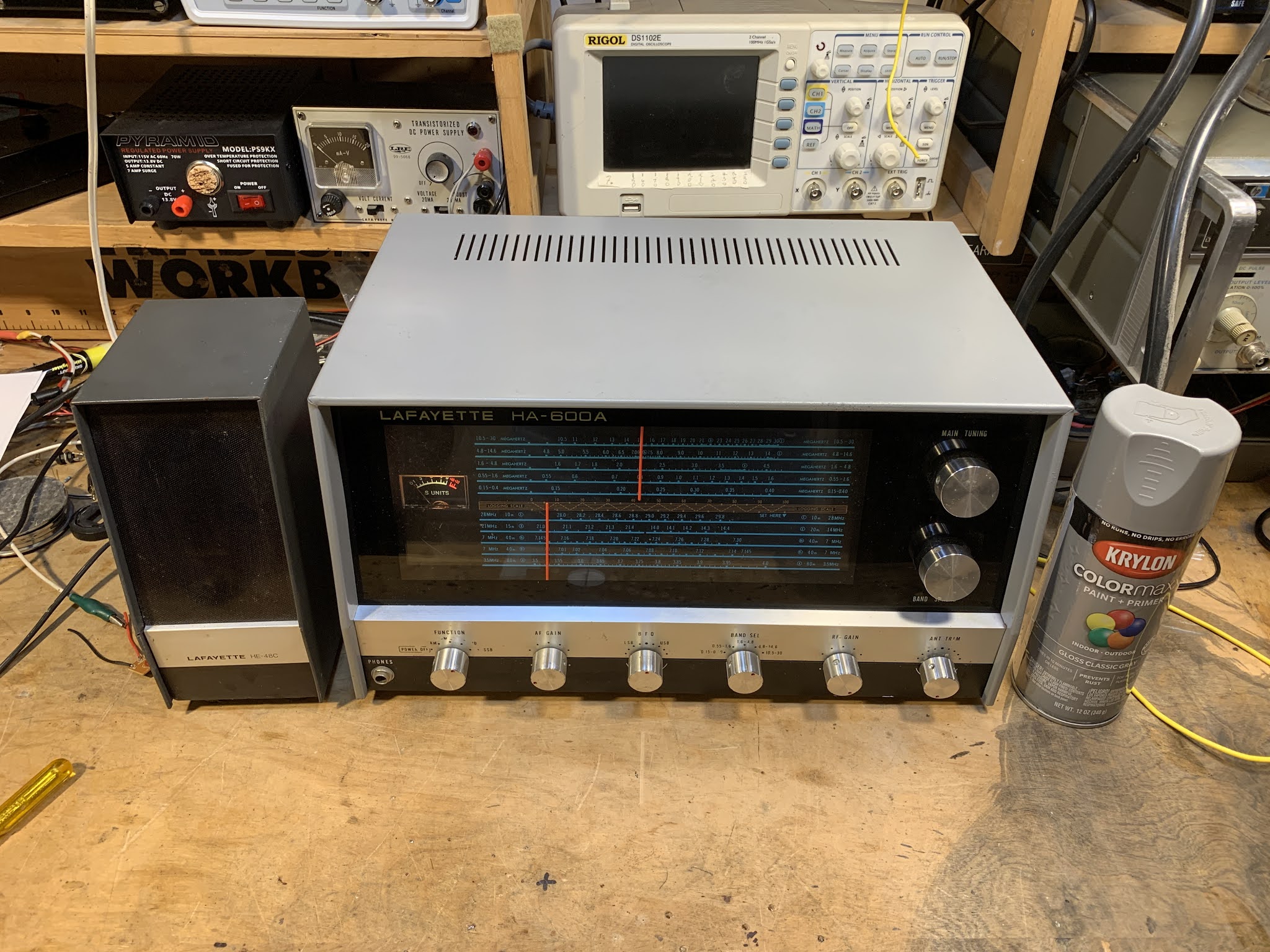
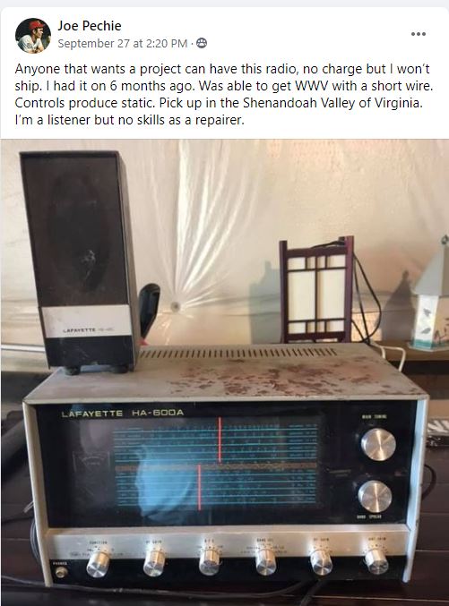
The HA-600A that I picked up last week was looking kind of sorry. There was a lot of rust on the cabinet. Below is the before picture.
I'm not really into cabinetry or radio aesthetics, but it is amazing what a 6 dollar can of spray paint can do. Formula 409 also helps. I moved the light bulbs forward a bit to get more light on that Juliano Blue dial.
I am really enjoying this radio. It has brought back many memories. I think I got one for Christmas in 1972. I was 14. I got my Novice ticket on April 27, 1973 and made my first contact on July 19, 1973. For that first contact I was using an HA-600A and a Heathkit DX-40. Later I used the Lafayette with a Heathkit DX-100. The HA-600A was replaced by the far superior Drake 2B on April 11, 1974. So I used this receiver for more than two years.
Looking around inside this receiver (and following up with Google) I learned some more about it:
-- It was made in Japan.
-- The manual says it has a "mechanical filter" but in fact it has a Toyo ceramic filter. This may have been just an honest mistake by the folks who wrote the manual -- maybe they didn't understand the difference between the two types of filters.
-- There is a big difference between the HA-600 and the HA-600A, mostly in the front end circuitry. The HA-600 has fewer amplifier circuits at the front end. This probably explains why the HA-600 I picked up did not seem to live up to my memories of my teen-year HA-600A.
The fellow who gave it to me tells me that it had belonged to the short-wave listener father of a friend of his.
I know we have a lot of tube-type receivers that are much older than this thing, but I still think it is pretty amazing that this is a receiver that I used almost half a century ago. And it is still as good as new.
So on September 27,2020, I was sitting quietly in my shack, perusing the postings on various radio-related Facebook groups, when suddenly I saw it: my very first shortwave receiver, the magic box that had put me firmly on the path to amateur radio, the Lafayette HA-600A. Joe, the owner, was offering it FREE to anyone willing to pick it up at his home in Virginia's Shenandoah Valley. Holy Cow! I was scheduled to drive through that very valley later that week. A message was sent and the deal was done. CLEARLY THE RADIO GODS HAD SPOKEN (TRGHS).
Sure, the cabinet looked a bit rough, but I had high hopes for this receiver. A while back I had -- in a similar fit of nostalgia -- bought what had been advertised as a Lafayette HA-600A on e-bay. But it turned out to be a Lafayette HA-600 (no A). I immediately noticed a big difference in performance. That was NOT the radio that I remembered, not the receiver that had carried HCJB and Radio Moscow to me. Joe was clearly offering the A model.
A few days later I was in Joe's front yard for the hand-off, and a few days after that the HA-600A was on my bench.
I quickly realized how little I knew about this receiver. Mine was a Christmas gift, probably in 1973. (A few days ago I talked to my mom and thanked her for driving all the way to New Jersey to get this receiver for me.) I was so taken with this thing that I feared doing something -- anything -- that might mess it up. I lived in fear, for example, that some sort of freak mid-winter lightning bolt might destroy it. I covered it with a towel each night lest dust encumber its "jeweled movements." Obviously I was just not inclined to crack open the case and have a look around. So I didn't, and the receiver remained pretty much an appliance for all the time I owned it. (I eventually sold it on consignment at Electronics 59 in Spring Valley, New York. The proceeds probably went toward the purchase of a much better Drake 2-B receiver.)
I downloaded the manual and familiarized myself with the receiver: It is a single conversion superhet with a 455 kc IF. It is all solid state with no ICs -- all discrete transistors and diodes. The manual claims it has a mechanical filter. I kind of hoped for something like a Kokusai mechanical filter, but it turns out that the filter was really ceramic, not mechanical. Bummer.
The thing fired up right away and was inhaling on the correct frequencies. I noticed immediately that (as Joe had indicated) some of the controls were scratchy. I also noticed that the ganged band selection switch was intermittent and required some jiggling to get it to work properly. A few squirts of Deoxit D5 took care of all that. There seemed to be a bit of dirt in the main tuning capacitor, but I think I managed to blow that out using a can of Dust-off. I was quickly listening to the SW broadcast stations, and to radio amateurs on 75 and 40 meters.
Out of curiosity, I compared schematics of the HA-600 and the HA-600A. There was indeed a big difference -- the front end of the 600 lacks a lot of the RFA amplification circuitry of the A model. That's probably why is seemed so deaf and so different from what I remembered of the A model.
There is really not a lot to do on this receiver. I'll get some paint to fix up the top cover. I may check the alignment. But this single conversion receiver is so simple that alignment would be quite easy. In many ways this receiver seems like a solid state analog to the Hammarlund HQ-100, but without the clock, and without the regeneration circuitry. The dial lacks the exotic station locations (Java!) that make many of the older receivers so much fun. I guess this is an indication that this receiver was aimed more at amateur radio operators than at shortwave listeners ( I was both). I wonder how the ham band-only HA-800 compares to the HA-600A?
I could pair this receiver up with a DX-40 transmitter that I have on the shelf and I'd be most of the way toward re-creating my novice station. Anyone have a Globe VFO Deluxe? That would complete the setup.
Thanks very much to shortwave listener Joe Pechie for providing what is, for me, a very meaningful piece of gear.
I'm more of a single conversion guy myself, but in working with the DX-390 I came to appreciate the benefits (especially regarding image rejection) of the double conversion technique. While working on the DX-390, I discovered that the BFO control on the front panel DOES NOT change the BFO frequency. It was fun to try to figure out why the designers did it this way. It does make sense once you consider the limitation imposed by that PLL main tuning oscillator that only moves in 1 kHz steps. I hope the video explains things. Here is the drawing I used in the video:
And here is a drawing that shows how a single conversion superhet with a fixed or switchable (usually crystal-controlled) BFO works:
Earlier this month I did a blog post on my repair of a broken DX-390:
I know what you are thinking: Software Defined radio with the TOTAL elimination of hardware? WHERE IS BILL AND WHAT HAVE THEY DONE WITH HIM? Relax my friends. All is well at SolderSmoke's East Coast HQ. In fact, just yesterday I was making use of one of the systems described in this video. Here's how: I was on 20 meters with my BITX 20 Hardware Defined (HDR) homebrew transceiver. Everything was going smoothly. We have some sunspots now, so DX is once again possible. I heard a loud U.S. station (that will remain anonymous) calling CQ, so I gave him a call. The trouble started right after he looked at my QRZ page. You see, I have pictures of my homebrew rigs there. These images sometimes trigger hostile reactions, especially from guys who have almost their entire stations INSIDE their computer boxes. I also admit to occasionally making things worse by pointing out that it is possible to build a BITX20 for about five dollars U.S. Some guys apparently don't like hearing about this. Anyway, the fellow I was talking to proceeded to give me a very blunt and harsh signal report: "Well, I suppose your signal is strong enough, but your audio is TERRIBLE!" Interpersonal relations pointer: This is NOT a good way to alert a fellow ham to possible technical problems in the rig that he has built by hand, from scratch, in his home workshop. Especially when the person delivering the harsh signal report is using a "rig" that was built by credit card in a robotic factory on the other side of the planet. So that QSO ended rather quickly. But I did want to follow-up in the comment about the audio. And here is where I turned to Web SDR. Mehmet NA5B has a really nice WEB SDR receive system in Washington DC, just about 8 miles east of me. Before 20 meters opened, I called up Mehmet's SDR on my computer, tuned it to the frequency of my transceiver and watched the screen as I asked if the frequency was in use. I then issued a couple of hopeless CQs, again watching the screen. I could see in NA5B's waterfall that my signal was indeed seriously lacking in low frequency audio. Now it was time to turn to hardware. Rig on the bench, 'scope and sig generators fired up, I quickly determined that the problem most likely resulted from my placement of the carrier oscillator frequency in relation to the homebrew USB crystal filter. I had placed it about 300 Hz too low. This resulted in a low AF frequency roll off not at the desired 300 HZ, but instead at around 600 Hz. That would make the audio sound "tinny." So I moved the carrier oscillator up 300 Hz and went back to Mehmet's SDR receiver. I could see that the lows were now at the right level. Thanks Mehmet. One note about the audio coming out of the many SDR radios on the air: When you look at the passbands in the Web SDR receivers you can see audio going almost all the way down to the frequency of the suppressed carrier. With non-SDR rigs you usually see a gap of around 300 Hz between the carrier freq and the start of the SSB signal. This is often the result of our filter rigs having IF filter skirts -- you would place the carrier oscillator frequency a bit down the skirt -- this would help with opposite sideband suppression and all you would be losing would be the lows below 300 cycles, which weren't really necessary anyway. I had placed the carrier oscillator too far down on the skirt. Of course, sometimes SDR rigs will also have a gap between the carrier freq an the start of the audio if the operator has set the passband this way, or if the microphone attenuates below 300 Hz. But you see a lot of signals with audio filling almost the entire passband --some of the "Enhanced SSB" guys are running audio passbands that go as low as 50 Hz. Has anyone else noticed this "full passband" effect when looking at the waterfalls? Any other tips for using Web SDR for troubleshooting?
The other day Pete N6QW posted a very nice graph of a bandpass filter's passband. He was using LTSpice. I realized I had a serious gap in my LTSpice knowledge -- I wasn't sure how to do this.
The charming video from India explains how. Really useful.
Paul Taylor VK3HN has really outdone himself in this video (above) and blog post. He describes coming across a somewhat mysterious homebrew SSB exciter with some cryptic markings on it. Paul eventually figures them out. We still don't know who the builder VK3WAC was -- can anyone find him in their logbooks? As Paul goes through the description of the transceiver he built around the mystery exciter, he mentions a number of hombew heroes including Farhan VU2ESE, Peter DK7IH, Eamon EI9GQ (I have to get his book!), and Don W6JL. Also, our beloved SSDRA book plays a prominent role in the story. Paul's video is really beautiful -- at one point the camera pans the landscape and we see kangaroos in the field. It is also refreshing -- as we suffer in the heat of the northern hemisphere summer -- to see Paul and his friends out on the summits in their winter coats and hats. It looks to me as if Paul built this rig during the current emergency, so I will list it as a Quarantine rig. Every dark cloud has a silver lining, and Paul's rig has added a bit of silver to the dark COVID cloud. Thanks Paul. https://vk3hn.wordpress.com/2020/07/26/something-old-something-new-a-four-band-5w-50w-ssb-cw-transceiver-summit-prowler-7/
The picture above shows my problem. As predicted by the Murata data sheet and as warned by R.A. Penfold, that nice 455 kc ceramic filter has a significant response at around 640 kc. This caused me to hear Brother Stair twice as often as I should have. Clearly a spur exorcism was called for.
Click on the picture for a better image. As noted last time, my first idea was to build a series 640 kc trap LC circuit and put it ahead of the ceramic filter. But I had trouble getting the desired high Q. So I then thought about putting a wider 455 kc filter ahead of my 12 kc filter. I would, of course, need one that did NOT have the 640 kc spur. I found a 455B filter in my junk box. I used the NanoVNA to look at its response. No spur at 640 kc! Yea!
Next I put the two filters together, 455B first, then the 12 kc filter. Success! You can see on the NanoVNA that there is no spur at 640 kc.
With close to the desired termination impedances, the passband at 455 kc looked pretty good. I just put 1500 ohm resistors in series at the input and output of the dual filter combo.
It worked. Spur exorcised! I no longer hear each SW broadcast stations at two spots on my dial.
"SolderSmoke -- Global Adventures in Wireless Electronics" is now available as an e-book for Amazon's Kindle.
Here's the site:
http://www.amazon.com/dp/B004V9FIVW
Solar Noise on the 28 MHz band - 10th May 2024
-
*10th May 2024:* I had the radio turned on in the background this morning
and I noticed a large burst of noise from the sun. I had the SpectrumLab
softwa...
Testing Unun losses
-
In his recent feedback, Richard, VK3TXD, suggested I measure the loss in
the Unun built with Jaycar LO128 core by making a second one and wiring
them back ...
An Inline RF Step Attenuator for QRPp Work
-
I don’t need to explain the attraction of low power operation; if you’re
reading this, the chances are that you are already a convert. I’ve been
operating ...
A 51S-1 Restoration Story
-
I came across my Collins 51S-1 in a big junkyard in Ankara, Turkey around
2012. It was in a pile with a lot of other electronic scrap, probably from
one o...
New QRP Cluster Online From OM0ET and OM6APN
-
By DX EXPLORER
DX EXPLORER
Paul OM0ET and Peter OM6APN recently launched a new cluster dedicated to
QRP operations. Have a look and I hope you will enjoy...
3D Printing The Hadley 114mm Newtonian Telescope
-
Yes, we’re building a 3D Printed Newtonian Telescope called Hadley. It’s
being printed in PETG and in the video below, I give a quick tour. My build
isn’...
3D printed project boxes
-
I have been busy with some other things that have kept me away from
electronics projects for quite a while. Now I can get back to them, but
realize I n...
Daylight Again – An all Analog Radio
-
What’s all this? In 10 seconds, A high performance, 7MHz, 5 watt SSB rig
Draws just 24 mA of current 90 dB dynamic range, 80 dB close-in dynamic
range 3D ...
Adding Enclosure to your sBitx Boards Order
-
The early buyers of the sBitx board set who bought it for $270 USD might
want to also add the enclosure (box) for in the kit. What you will now get
is a f...
Digi-chirp! Digital synthesis of ‘nostalgic’ CW
-
The bottom ends of 80, 40 and 20m are not what they used to be. For
starters, the busiest part is the digital segment where computers talk to
computers – l...
-
A Simple Speech Processor
(For QRP/SSB Homebrew Transceivers )
Over the last few weeks I had been thinking to build a small AF speech
processor to add to...
A New Look for your uBitx!
-
Adding a "Cool Blue" Display to your uBitx!
The standard "green background" with black lettering frequently reminds me
that I suffer from Chronic seasickn...