Podcasting since 2005! Listen to Latest SolderSmoke

Showing posts with label Rainey -- Michael. Show all posts

Monday, July 18, 2011

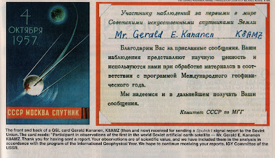
Sputnik QSL from the Soviet IGY Committee

I like the reminder of Sputnik's IGY connection. This is from an article by John Foley. W7ETS, in the October 2007 issue of QST. Be sure to read the translation in the caption.

Yesterday Billy and I were at the Smithsonian Air and Space Museum's Dulles Airport center. (We volunteer to take visiting relatives to the airport IF we get to go to the Smithsonian afterwards.) We checked for Sputniks. Nyet. I think they have one on display in the main Air and Space building.

I was thinking that listening to a signal from a spacecraft should be part of the Sputnik event. The packet 2-meter signals from the International Space Station are probably the easiest to receive these days.

Check out "SolderSmoke -- Global Adventures in Wireless Electronics"http://soldersmoke.com/book.htm

Thursday, July 14, 2011

Sputnik Madness! But was it CW? or AM?

Our worldwide team of Sputnik enthusiasts continues to seek out the elusive schematic diagram of the spacecraft's 20 MHz transmitter. American, Cuban, Russian and German radio amateurs are involved. Recently Bruce, KK0S, visited the Kansas Cosmosphere in an effort to get a look at the innards of Sputnik's "flight spare." The picture above is his -- it shows the Sputnik antenna connection. (More pictures from Kansas here: http://s747.photobucket.com/albums/xx120/trader_vic/Kansas%20Cosmosphere/)
There was bad news and good news from the visit: The bad news was that the spacecraft on display was a hollow sphere. The good news is that the internal parts --including the transmitter -- might be in storage someplace, just waiting for our reverse engineering. Stay tuned (to 20 MHz!).

Speaking of which, I have a question: OK so the crafty Soviets picked 20.oo5 MHz for some good reasons: Being so close to the WWV freq, it would be easy for hams and SWLs to find it with precision. In the November/December 2007 issue of "Break In" (from NZ -- thanks Jonathan-san!) ZL3DW notes that this frequency selection would allow a receiver set to exactly 20 MHz to "produce an audio tone plus or minus the Doppler shift without ever going through zero beat." But zero beat with what? Most of the receivers out there would not have had BFOs, right? So the Soviets wouldn't have been using ordinary CW, right? Were they using AM, with the beeps produced by an audio oscillator modulating the carrier?

Here is a update from our Chief Designer, Comrade Mike, AA1TJ:

I currently have a prototype for a simple "Sputniker" transmitter on the bench using a 1sh29b in the oscillator and a 1p24b working as the PA. As in the original, the input
DC PA power is 1watt. The crystal-controlled oscillator uses an inexpensive ESS 21.060kHz xtal. So far, all systems are GO.

BTW, here's an example of how inexpensively these lovely little tubes may be purchased. Oleg, RV3GM, and his pals might be able to do even better.

Although there are only so many ways one can build a two-tube, crystal-controlled MOPA transmitter, we'd still very much like to nail down the original transmitter circuitry. Bruce, KK0S and Peter, DL2FI are following up leads to that end.

Once we're a bit further along I'm hoping that someone will step-up to produce a kit. Actually, last evening someone raised their hand to ask if a kit were already available.

Dasvidania,
Mike, AA1TJ

Saturday, July 2, 2011

WOW! The Reverse Beacon Network


In the European dispatches of Mike AA1TJ I saw mention of this new thing called the Reverse Beacon Network. Then SPRAT shows up in my mailbox (HOORAY!) and I see mention of the RBN there. So this morning I figured I'd give it a little test: I called CQ on 40 meters using my Heathkit HW-8. WOW -- it didn't take RBN long to get me! See above. That's after only about 3 minutes of CQing.

This is a really amazing and innovative development. The network makes use of "skimmers" that use Software Defined Radios connected to the net to search for CQs. When they hear one, they automatically post the info on the web. It is sort of like WSPR, but it is aimed at ordinary CQ calls. Fantastic. Check it out. You will like it!

Saturday, June 18, 2011

AA1TJ: Hiking through Austria, Thinking about Sputnik


The Hero of the Hobbit Hole and Poet Laureate of QRP, Michael AA1TJ and his wife Vicki are hiking through Austria these days. Michael is on the air with a rig powered by one D-Cell battery. Now, I'd like to tell you guys that through some MIRACLE of electronics he sent us this video via that D-Cell rig, but it's not April 1. And even if it were April 1, I'd be reluctant to use that as my gag because, given Michael's high level of operating and technical skill, there is always the risk that he'd find a way to do actually do it!

Anyway, as he makes his way between ancient Roman signal towers and picturesque Austrian villages, Michael has been thinking (as you do) about the schematic diagram of the radio transmitter on the Sputnik satellite.

Gentlemen, we need this diagram. And it is not (GASP!) available on the supposedly all-knowing internet.

Here is Michael's message:

Hi Bill,
I've been thinking about "Sputnik Day" while hiking this past week or ten days. Bill, I think we've really got to do this. Many thanks for your help so far...the Kansas Connection is very tantalizing! I know you have a lot on your plate but if there is anyway you could move things along with the Kansas possibility it would be fantastic.

If we approach the museum in a professional manner...pointing out the historical necessity for properly documenting what they have, I can't see how they could refuse us. Next, we would need to assemble a team of technically competent (and appropriately diplomatic) amateurs to go in to photograph the transmitter and trace the schematic.

All the best to you and the family. Again, I think Sputnik Day could really fly...it has every aspect you could ask for...big history, home brew, QRP, contesting...

Any help or ideas from you would be most appreciated.
Tschuess, Mike, AA1TJ
Sent from my iPad

Is there somebody out there in Kansas who could take charge of this project? I agree with Michael: Essentially three steps:
1) Write to the
Kansas Cosmodrome museum seeking permission to examine the innards of the satellite.
2) Once permission is granted, one or two guys could go and take detailed photos of the transmitter and gather as much data as possible about the rig.
3) From these pictures, we could trace out the diagram.

Not only will we have what we need for Michael's Sputnik Day construction project, but we'll be making a real contribution to radio history.

We don't want multiple approaches to the museum, so maybe it would be best for anyone who is willing to do this to contact me first.

This should be fun!


Tuesday, June 7, 2011

Searching for the Sputnik Schematic

Mike, AA1TJ, has launched (!) yet another intriguing project. See below. In an effort to come up with the actual Sputnik schematic, I have thrown down the geek gauntlet to our fellow nerds at sci.space.history:

Greetings Space Historians!
We are a group of radio amateurs and we probably rival you in our
technical geeky-ness. We are now involved in an effort to re-create
and put on the airwaves replicas of the 20 MHz transmitters used in
Sputnik 1. (We will use the amateur radio 21 MHz band).
We are trying to find a schematic diagram for the transmitter. Can
you help us? Thanks.

------------------------
Gentlemen,

Arnie, CO2KK, told me last night that as a 15 year-old boy he'd made
it into the newspaper by picking up Sputnik's signal on his Hammarland
Super-Pro receiver.

Don Mitchell - a physicist now retired from the Bell Labs - also wrote
last evening to ask if I knew of a schematic diagram for the two
transmitters used on Sputnik-1. Mr. Mitchell maintains an informative
web site on the topic of Sputnik. Here, for example, is the link to
his page on the first of the series of "Travellers" to be lofted into
orbit in late 1957 into 1958.

http://www.mentallandscape.com/S_Sputnik1.htm

To the best of my knowledge the schematic for what may be the most
famous QRPp transmitter has never been published. It's a shame,
particularly as it would have been great fun to build an approximate
replica for use on the ham bands

However, I woke up this morning wondering why should we allow the lack
of an original schematic to stop us when there's plenty of descriptive
evidence available? "Spaceflight Magazine," for example, published a
wonderful article on the 50th anniversary of Sputnik. The story was
pieced together from original documents over a period of 20 years. You
may read the article here

http://faculty.fordham.edu/siddiqi/writings/siddiqi_sputnik_history_2007.pdf

"The two D-200 type radio transmitters operated on frequencies of
20.005 and 40.003 megacycles at wavelengths of 15 and 7.5 m. These
transmitters (which obviously used vacuum tubes) each had a power
intake of 1 watt and provided the famous “beep-beep-beep” sound to
Sputnik. The signals on both the frequencies were spurts lasting 0.2
to 0.6 seconds, and carried information on the pressure and
temperature inside the satellite; one set would transmit during the
“pauses” of the other."

"Despite objections from just about everyone, Gringauz insisted that
PS-1 carry a high frequency transmitter (the 20.005 MHz transmitter
operating in the decameter waveband) in addition to the VHF
transmitter (which had been commonly used on Soviet ballistic
missiles). ...In the end, Gringauz won over his opponents, partly
because everyone agreed that a high frequency
transmitter would ensure that the radio transmissions would be heard
around the world. The transmitter hardware was built by one
of Gringauz’ youngest engineers, Vyacheslav Lappo..."

>From other sources we know the transmitter used vacuum tubes rather
than transistors. This site mentions that when the received signal
level
was quite strong, the presence of a back-wave while the other
transmitter was keyed could be noted.

http://www.amsat.org/amsat/features/sounds/firstsat.html

The RF oscillator, at a minimum, must have been free-running. So,
we're talking a vacuum tube crystal-controlled oscillator and a PA
having an input power of 1 watt. They may have used a PA driver stage,
or perhaps a frequency multiplier stage. If they did use a multiplier
then it must have been allowed to free-run as well. But given the
battery drain considerations, I would have done my best to reduce the
number of vacuum tube heaters, or filaments to a minimum. As such, I
think there's a fairly good chance this was a simple, MOPA design
(oscillator-> PA).

I found what might be a photograph of the transmitter on page 26 of
the December 1957 issue of the Soviet "Radio Magazine." Perhaps our
Russian speaking group members can confirm this and provide us with
other clues appearing in the article text? The magazine can be
downloaded at

http://publ.lib.ru/ARCHIVES/R/''Radio''/

Click-on ''Radio'',1957,N12.[djv].zip. The "zipped" December issue
appears in DJVU format. Don't miss the nice Sputnik cover art.

This re-post talks about the center-fed Vee dipole used (the 15m
transmitter used the 5.8meter dipole) among other things.

http://hamradio.mybb.ru/viewtopic.php?id=625

Getting to get the point, this morning I woke up thinking about how
plentiful vintage Russian military tubes are these days. Remember how
inexpensive US military surplus used to be? That's how it is right now
with Russian components (and the characteristics of some of these
tubes are simply amazing). All I can say is get 'em while they're hot,
as it surely won't last forever.

It also came to me that Expanded Spectrum Systems sells an HC49
crystal cut for 21060kHz for two and a half-bucks each.

Finally, I remarked to myself that propagation-wise, 15m may well be
open for business come the 54th anniversary of the launch of Sputnik-1
next October the 4th.

You've probably guessed by now what I'm going to propose. We have
plenty of time to throw together a simple 15m CW vacuum-tube
transmitter having an input power of 1w or less. We could use any
tubes that we like but I'm going to build mine using 1950's vintage
ex-Soviet devices. I plan to power mine with one or two of those
ubiquitous 12V sealed-lead-acid batteries. I'll VXO my crystal and
I'll let it free-run during transmit; both for historical reasons and
to improve the signal quality.

Perhaps some of the antenna gurus here would lend a hand by modeling
and testing something akin to the original 70 degree Vee dipole? Would
this be a practical antenna?

I propose that beginning on "Sputnik Day" we launch our 1 watt Sputnik
clones on 15m CW. Instead of calling CQ, our call could be along the
lines of "Beep_Beep_Beep_Beep_Beep_Beep de AA1TJ". In other words, six
letter E's followed by our call sign. Given that I can barely organize
the socks in my underwear drawer, perhaps someone skilled at
organizing events would take up the cause?

One more thing. Poking around on Google last night, I was struck by
how many people remarked that the experience of Sputnik had changed
their lives. Some decided to become engineers, scientists or amateur
radio operators. I didn't know it at the time, but Sputnik changed the
way that I was educated. Not only did this little QRPp transmitter
make a tremendous impact on the world, but radio amateurs were front
and center. It seems appropriate that we should commemorate this
extraordinary day in the history of QRPp.

http://www.youtube.com/watch?v=CHaJDuq6tBM

(they were seeing the orbiting booster stage rather than the satellite)

Sputnik Mania...the complete film in two parts (warning...contains
some political "button-pushing")
Greetings Space Historians!
We are a group of radio amateurs and we probably rival you in our
technical geeky-ness. We are now involved in an effort to re-create
and put on the airwaves replicas of the 20 MHz transmitters used in
Sputnik 1. (We will use the amateur radio 21 MHz band).
We are trying to find a schematic diagram for the transmitter. Can
you help us? Thanks.


http://www.youtube.com/watch?v=8jI5RBRWIOE

If I happen to learn more about the original transmitter I'll be sure
and post it on my blog or web site. I found particularly interesting
the fact that WWV interrupted some of their 20MHz transmissions in
order to accommodate Sputnik's signal; a gentlemanly thing to do

As for the possibility of an event along these line, any comments or
discussion is most welcome. I plan to make a start on my little
Sputnik sender upon my return from vacation in July.
Greetings Space Historians!
We are a group of radio amateurs and we probably rival you in our
technical geeky-ness. We are now involved in an effort to re-create
and put on the airwaves replicas of the 20 MHz transmitters used in
Sputnik 1. (We will use the amateur radio 21 MHz band).
We are trying to find a schematic diagram for the transmitter. Can
you help us? Thanks.

Ha...I just received several fairly good-quality color photos of the
original Sputnik transmitters! At first glance it looks as though they
used two subminiature pencil tubes! The quartz crystal looks very
similar to our HC-18/u package. The RF portion is very simple in
appearance. In fact, it reminds me of something you'd find in a 1950's
ARRL Mobile Radio Manual! ;o)

The fellow who sent these apparently has a contact with one of the
original Sputnik (non-electronic) hardware designers; who is said to
be "still very much alive." My contact is going to make an inquiry
with his Russian contact about the transmitter.

Very cool...

73/72,
Mike, AA1TJ

Saturday, April 9, 2011

Another QRPoet

I'm a big fan of Ade Weiss, and I often find myself reaching to his "History of QRP" for technical or techno-literary inspiration. Most writing about ham radio is (understandably) done in a very straightforward technical way, without a lot of emotion. But Ade's writing style captures both the technical and the emotional aspects of homebrewing and QRP. There is a definite poetic elements to it. This article was sent to us from the Hobbit Hole by the Poet Laureate of QRP (AA1TJ). Just click on on the image to enlarge. From a 1973 issue of The Milliwatt:

Thursday, March 25, 2010

Polyakov's Russian Mixer

I'm planning on building a DC receiver for use with the WSPR system. I will probably follow W3PM's lead and put a crystal filter between the antenna and the mixer. This will be a fixed frequency receiver aimed at one 200 hz slice of the 30 meter band.

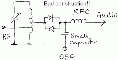
Of course, the big question is what mixer circuit I should use. I'll probably go with an SBL diode ring, but while perusing the literature, I again came across "The Russian Mixer" of Vladimir Polyakov, RA3AAE. Michael, AA1TJ, is a big fan of this circuit, and has been talking about it on Radio Havana Cuba. What a cool circuit it is! Just two diodes in parallel, cathode to anode. RF from the antenna goes in one side, and the local oscillator signal is placed at the other end. The LO signal causes the diodes to turn on and off on voltage peaks, effectively chopping up the incoming signal, producing sum and difference frequencies. LA8AK's drawing of one version of this circuit appears above. (Obviously OM AK didn't like this configuration, but it gives you the idea.)

The really cool part is that because you have two diodes, the "chopping" takes place at TWICE the LO frequency. This happens because on a positive LO peak one of the diodes conducts, and then, on the negative peak, the other conducts. So it is as if the mixer gate is opening twice each LO cycle. This allows you to run the oscillator at half the operating frequency, with advantages for stability and for the effort to eliminate common mode hum.

A while back I saw (somewhere!) a clever use of this circuit. LO was running at around 3.5 Mhz. With the two diodes in the circuit, it was a 40 meter receiver. They had a switch that could remove the second diode from the circuit. By throwing this switch, the RX went to 80 meters.

Does anyone remember this circuit? Where did it appear? SPRAT? QQ? Tech Topics? I can't find it.

I had the impression that OM Polyakov was active in the early days of radio. But some Googling shows that he is of much more recent vintage, still active and listed on QRZ.com. Here he is:

Friday, November 13, 2009

Final Report from the Maine Code Talker/160 QRP Rexpedition

Rex, W1REX, has a really nice article on this week's historic QRP expedition to the Maine coast. As you have read in this space, Michael, AA1TJ, challenged the mighty Atlantic with nothing more than the 15 milliwatts generated by his own voice. No joy this time, but we are sure that Michael will soon experience the same thrill felt by Marconi when that first, faint S was heard on the other side. Seab, AA1MY, overcame serious kite problems and fulfilled a long-held QRP ambition by working across the pond on 160 meters with less than 5 Watts. Congrats Seab! Congratulations to all the Rexpedition team members. It has been really fun to follow your adventure.

Read all about it here: (The link to the Rexpedition article is near the top of the page, but don't miss the wonderful kits that Rex is offering further below!)

http://www.qrpme.com/

Wednesday, November 11, 2009

AA1TJ Code Talker on the Maine Coast


Apparently no voice-powered transatlantic joy yet, but we all know it is just a matter of time. And I think this will be something completely new in radio history! Great try guys! Keep at it!

From W1REX last night:

We started about 8:45 am this morning, because AA1TJ was too excited to
wait any longer! He shouted into his #2 can for a couple of hours until
I thought he was going to burst a vessel....and I'm not talking about
one of the many passing by out on the ocean. We thought that we had a
2-way QSO a couple of times but the returns were simple lost in the
noise. Michael ran out of steam....or breath...and none of us old-timers
could cut the mustard..or soup...or whatever was in the can.

Seab, AA1MY, launched the kite last night prepping for an attempt at a
160m record. He intended to operate on 1.811 and cross 'the pond' with a
minuscule signal but the bridle broke on the kite and it sailed away....
It could be on the other side of the pond for all we know, as it was
never seen again. He launched a back-up kit tonight and had it up there
into the lower stratus-sphere but needed just a little more height as
there was still some antenna wire on the ground...but alas, the wind
came to an abrupt stop and the flying kite came to an abrupt just a
short time later.

So to sum up todays results: ZILCH!

We want to thank EVERYBODY who kept an ear out for us today and hope you
have the time and patience to try it again tomorrow morning!!

TOMORROW'S ITINERARY:

We have more wire up on 20m and will attempt another across the pond QSO
starting at 8:00AM local time or 1300 Zulu. Mike has to pick up his wife
at the airport in NH so the attempt will terminate long about 9:30AM
local time. So we have another 90 minutes to try for the record and YOU
have another 90 minutes to be a part of it. Listen in at 14.055 MHz
starting at 1300 hours. Put your good ears on and listen sharp... Hope
you hear us AND we hope to hear you hearing us...

Seab will take another stab at the 160m record (MAINE weather
permitting) probably around 700AM local time 1200 Zulu. He is
heartbroken that his dead-cert kit took a powder and dashed his dream.
Little back-up kite and a sightly altered antenna farm hopefully will
come through for him. Give a listen over there on the other side of the
Atlantic.

Monday, November 9, 2009

Transatlantic Team Heads to the Coast!

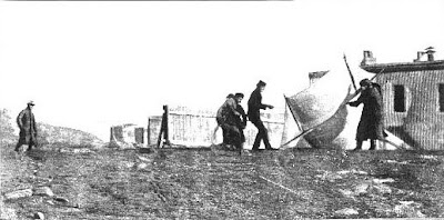
When it comes time to cross the pond, it seems only natural to head to the beach. That's what Marconi did (above we see his team struggling with a kite at Newfoundland). And that is what AA1TJ, W1REX, AA1MY and W1PID are doing today and tomorrow. Here is Michael's message to QRP-L describing the expedition. Good luck guys!

Some of the lads are heading over to the Maine seacoast on Monday
morning for what we're calling a "Rexpedition." W1REX was kind enough
to secure the use of his family's beachfront camp for us for a couple
of days. He explained the urgency to them, saying, "...a bunch of
radio-heads want to talk to Europe with the equivalent of a cellphone
with a dead battery."

Rex, Seab, AA1MY and Jim, W1PID, are going to arrive early on Monday
to begin putting up the antennas. I plan to show up in time for lunch;
hopefully after all the hard work is done. Seab wants to erect a pair
of half-wave phased verticals on 20m. I think the plan is to lift a
160m antenna using one of Seab's big kites.

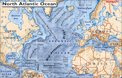
Our hope is to cross the pond on both 160m QRP and with my
voice-powered 20m transmitter. The weather forecast looks great at
least through Tuesday. My "Code Talker" will be rockbound on
14.055MHz; same as last Thursday. We'll begin the voice-powered 20m CW
attempt the first thing on Tuesday morning (11/10/09). Again, the goal
is to span the Atlantic, but as always, I'll be very pleased to work
anyone that hears me.

By the way, last Thursday's voice-powered operation on 20m was a great
success. Altogether, I worked four stations and received one SWL
report. The best DX was W4FOA in Chickamauga, GA; a distance of
923miles. Tony reported that my 15mW signal was "an honest 579". W4OP
- located one hundred miles to the north of Tony - handed me the same
report and followed up with an amazing recording (you can hear it on
my website). Later in the day I received an email from AD5VC. Dana
reported that he clearly copied my callsign while listening on the LSU
club station (K5LSU) in Baton Rouge; a distance of 1375miles (nearly
half the distance between the Maine coast and London, England).

I thought these were remarkable results for 15mW into an endfed wire
at 35 feet. It makes next week's attempt from a saltwater QTH, coupled
with the low-angle of radiation with a spot of directional gain all
the more exciting.

So please keep us in mind come next Tuesday morning. I'm guessing Seab
will be operating 160m QRP on both Monday and Tuesday evenings.

Thank you,
Mike, AA1TJ

Sunday, November 1, 2009

Crossing the Pond... with the power of your voice

Michael Rainey, AA1TJ, has his eye on the North Atlantic. He's been thinking about maritime horns, and how far they could reach. He's built another kind of horn. I'm pretty sure that this one will soon take his voice and -- using ONLY the power of that voice -- send it across the mighty Atlantic. That's a pretty astonishing horn!

Yesterday Michael put a really nice message up on the QRP-L list. This is the kind of message that has earned him the title "Poet Laureate of QRP." Here is an excerpt:

I'm currently sitting at a desk on top of Vermont's highest mountain.
In the far distance I can see the Presidential mountain range of New
Hampshire
. Roughly twice as far away is the Atlantic Ocean. The other
night I spoke into a tin can, and the power of my voice carried a
message to the Maine seacoast where K1MPM heard me as clear as a bell.
I think this is absolutely magical. The present prospect of blowing
into a tiny horn and having this pittance of exhaled energy carry a
message back to England - when the bone shaking horn on the old Queen
Mary
couldn't carry to the horizon - is nearly beyond comprehension. I
know this is how everyone of us feels when we operate QRP.

Read the rest of Michael's message here:
http://mjrainey.googlepages.com/lavoixdesoc%C3%A9ans

Tuesday, October 27, 2009

Listen to "El Silbo" Voice-Powered Rig!

POWER SUPPLY

Michael, AA1TJ, has had more contacts with his voice-powered DSB rig. (Scroll down a bit for a look at the schematic and more comments on this amazing project.) Michael has posted two recordings of his signal (as received at distant stations). When I played these files, Ubuntu showed one of those semi-psychedelic groovy "visualizer" displays, complete with oscilloscope-like patterns; the signal looked FB Michael!
Have a listen: http://mjrainey.googlepages.com/elsilbo

Saturday, October 24, 2009

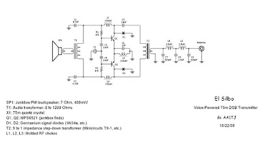
"El Silbo": Michael Rainey's Amazing Voice-Powered DSB Transmitter


Oh man, the wizard of the Vermont hobbit hole has really outdone himself this time. Michael Rainey, AA1TJ, has posted a very interesting report on his experiments with voice-powered radio. I was, of course, delighted that he went with DSB. Check it out: http://mjrainey.googlepages.com/elsilbo

I don't mean to seem like I'm taking any credit for this, but I did provide Michael some technical advice on how to increase power output:

Michael: Obviously the Italian elements in the project were of critical importance. Some of them may have escaped your attention. I note that an olive can was involved... For further progress I think you should consider working in some of the other substances that help keep Italy going: cappuccino, Nutela, and perhaps some vino bianco...

Another thing: While you are shouting, be sure to use the proper gesticulations. I recommend that you go Neapolitan here -- they are the best. I'd say that before each CQ, you should put yourself in a Neapolitan frame of mind: imagine that someone has bumped into your car and that you and the other guy are arguing about who is at fault. This should generate at least 20 mW!

In boca a lupo! 73

Bill
Designer: Douglas Bowman | Dimodifikasi oleh Abdul Munir Original Posting Rounders 3 Column