Podcasting since 2005! Listen to Latest SolderSmoke

Wednesday, January 28, 2015

Back Into the Digital Morass


Using a very nice M0XPD AD9860 shield from Kanga-UK and software by Richard AD7C I put together another little DDS VFO.  This one went together without a lot of hair pulling.  I put the LCD, brightness control and rotary controller on one piece of vero board -- this will also serve as the front panel.  


Our book: "SolderSmoke -- Global Adventures in Wireless Electronics" http://soldersmoke.com/book.htm Our coffee mugs, T-Shirts, bumper stickers: http://www.cafepress.com/SolderSmoke Our Book Store: http://astore.amazon.com/contracross-20

Tuesday, January 27, 2015

The Battery That's Been Working for 175 Years


In case you missed this.  Makes you think, doesn't it?  I'm thinking of a QRPp QRSS transmitter that would just keep on going.  Battery designed by Giuseppe Zamboni.  

http://motherboard.vice.com/read/this-battery-has-lasted-175-years-and-no-one-knows-how

Our book: "SolderSmoke -- Global Adventures in Wireless Electronics" http://soldersmoke.com/book.htm Our coffee mugs, T-Shirts, bumper stickers: http://www.cafepress.com/SolderSmoke Our Book Store: http://astore.amazon.com/contracross-20

Monday, January 26, 2015

New Analog Frequency Readout for BITX17 VXO


I've been getting tired of being in the dark about the frequency on which my BITX17 was operating.  So I pulled out some graph paper, my frequency counter, and a pencil.  You will see two frequencies at each point -- that's because  I use two crystals, switched by the black knob on the left.  I realize this paper and pencil approach is hopelessly out of date, but I see it as "appropriate technology" for a discrete component all-analog transceiver.  

Pete set me straight on how to come up with the numbers: VXO frequency minus  ACTUAL carrier oscillator/BFO freq.  After doing this I took great delight in going on the air and asking guys with fancy "glowing numerals" rigs to compare their freq readout with my pencil and graph paper readouts: they were painfully close.    

But I am not slipping completely into stubborn Luddite-ism; this weekend I worked on a DDS-based AD9850/Arduino VFO with I-Q output based on Paul M0XPD's Kanga-UK Arduino Shield.   STAY TUNED! 

Our book: "SolderSmoke -- Global Adventures in Wireless Electronics" http://soldersmoke.com/book.htm Our coffee mugs, T-Shirts, bumper stickers: http://www.cafepress.com/SolderSmoke Our Book Store: http://astore.amazon.com/contracross-20

Sunday, January 25, 2015

Jailed for The Knack: Gerry Wells, Homebrew Hero


Thanks to Thomas of the "SWLing Post" for alerting us to the story of UK radio legend Gerry Wells. As Thomas said in his post, you really need to drop what you are doing and listen to this great BBC program about Gerry: 

http://swling.com/blog/2011/02/radio-documentary-the-wireless-world-of-gerry-wells/

The poor fellow was actually JAILED for his "radio obsession."  Wow.  That was kind of harsh.  But Gerry overcame adversity and had a very happy life in radio.  

Thomas has more on Gerry here: 

http://swling.com/blog/2014/12/jonathans-interviews-with-gerry-wells/

Thanks Thomas!  And thanks to the BBC. 

Our book: "SolderSmoke -- Global Adventures in Wireless Electronics" http://soldersmoke.com/book.htm Our coffee mugs, T-Shirts, bumper stickers: http://www.cafepress.com/SolderSmoke Our Book Store: http://astore.amazon.com/contracross-20

Saturday, January 24, 2015

VE3MKC's Teensy Si5351 SDR Receiver with a Tiny Color Screen (video)


From: Rich 
To: "soldersmoke@yahoo.com"  
Sent: Thursday, January 22, 2015 9:22 AM
Subject: Cheap, open source Arduino SDR project
Bill
First, thanks for Soldersmoke and all you do for us QRP hackers around the world. I'm a big fan!
I've detected you are getting sucked into the world of microcontrollers of late. I know you are not really that excited about SDR but this is a radio that combines Arduino, the currently popular SI5351 and a Softrock to make a very functional SDR. I started this project last year which uses the fabulous Teensy 3.1 and companion audio shield. I recently packaged it all up and it looks like a QRP radio now. Still doesn't transmit but as I like to say thats "just a small matter of software".
There are several posts about it on my blog. The most recent:
There's a link to a video and a link to the code in that post.
Rock on Bill!
73, Rich Heslip
VE3MKC


From: solder smoke
Sent: Friday, January 23, 2015 4:09 AM
To: 
Subject: Re: Cheap, open source Arduino SDR project
Wow Rich that is really beautiful.  Amazing!   I am also sending this to Pete Juliano, but I was at first hesitant about this because I feared that your combination of Si5351 and TFT display might be TOO exciting for him. Deep breaths Pete...  
73 and Thanks,  Bill 


From: jessystems@verizon.net
To: soldersmoke@yahoo.com; 
Subject: Re: Cheap, open source Arduino SDR project
Date: Fri, 23 Jan 2015 06:03:40 -0800

Hi Rich & Bill,
Wow –really exciting project Rich! Congratulations and Bravo!
This is so exciting, for all hams, as this just shows the power of the available low cost technology that is now on the market. Your project is really tempting as I have a V6.2 15M softrock sitting in a box (somewhere). I was somewhat put off with the Power SDR as the opposite sideband rejection is not too good –it is clear you have cracked that nut.
Thanks for sharing Rich and yes Bill I am taking very deep breaths.
73’s
Pete N6QW


Our book: "SolderSmoke -- Global Adventures in Wireless Electronics" http://soldersmoke.com/book.htm Our coffee mugs, T-Shirts, bumper stickers: http://www.cafepress.com/SolderSmoke Our Book Store: http://astore.amazon.com/contracross-20

Friday, January 23, 2015

DuWayne's AD9850 Arduino TFT SWR Scanner


This is really nice.   DuWayne KQ4VB, has been talking to Pete about his use of digital chips, Arduinos and TFT displays in homebrew SWR analyzers.   Obviously these techniques could be used to measure the passband of crystal filters.  (Far superior to my pencil and paper procedures.)  Nice work DuWayne!


Pete
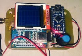
Looks good, I did some playing with the TFT board I have.  Did a board for the antenna analyzer using the TFT and a 9850 DDS module insted of the NOKIA and si5351.  Wanted to see if there was much difference between a sine wave out and the square wave from the 5351.  Appears to be very nearly the same from a couple of quick tests I have done.  Want to try some different diodes and change some values for amplifier gain.
Will keep you informed. DuWayne

Earlier... (4 November 2014)

Pete
Really enjoy listening to you on Solder-Smoke.  Saw the link to your
xcvr with the Adafruit si5351 board.  I got a couple of them and have
been playing with code for them.  Have been spending most of my time
working on an antenna analyzer based on the one by K6BEZ. Pleased to see
your article in the latest QQ.  I have used basically the same circuit,
except am using  the little NOKIA LCD display. The resolution is not the
greatest  but works well for this application.  I am using some of the
original code from K6BEZ to talk with his existing PC program.  For
stand alone I have 2 modes, a straight tune mode where I can select the
frequency and read the SWR.  Also implementing a sweep mode that scans
the whole band and after it is finished you can tune across and see the
frequency and SWR.  I am attaching a couple of pictures of what I have
so far. Waiting on the correct op amp to arrive and making some changes
to the amp gain to get better results on the higher band where the
output of the DDS drops off.
Thanks for all the inspiration you give to us home builders and tinkerers
out here.
73 DuWayne   KV4QB


Our book: "SolderSmoke -- Global Adventures in Wireless Electronics" http://soldersmoke.com/book.htm Our coffee mugs, T-Shirts, bumper stickers: http://www.cafepress.com/SolderSmoke Our Book Store: http://astore.amazon.com/contracross-20

Thursday, January 22, 2015

Interesting Propagation Web Site

CONUS HF BAND CONDX
1/22/15 --- 10:45:00 GMT --- REPORT # 1289
160 80 40 30 20 15 10

I think this is a really interesting and useful way to gather and present information on propagation conditions.   Check it out.   The "instructions" page gives some background info on the technique used. 

http://www.bandconditions.com/ 

The author, Biz, K5BIZ seems like a very FB ham: http://www.qrz.com/db/K5BIZ


Our book: "SolderSmoke -- Global Adventures in Wireless Electronics" http://soldersmoke.com/book.htm Our coffee mugs, T-Shirts, bumper stickers: http://www.cafepress.com/SolderSmoke Our Book Store: http://astore.amazon.com/contracross-20

Wednesday, January 21, 2015

Star City Antique Radio's Beautiful Workshop


Dale Cook of Star City Antique Radios and Test Gear has a really nice site with great pictures of his workbenches and test gear.  Inspirational stuff.  Take a look: 

http://plymouthcolony.net/starcity/radios/pages/compact.html

Our book: "SolderSmoke -- Global Adventures in Wireless Electronics" http://soldersmoke.com/book.htm Our coffee mugs, T-Shirts, bumper stickers: http://www.cafepress.com/SolderSmoke Our Book Store: http://astore.amazon.com/contracross-20

Tuesday, January 20, 2015

All of the Shortwave Spectrum LIVE on Web Waterfall Display


It's been a while since I checked in with this site.  They have made a lot of improvements.  It is very impressive.  I had trouble with it using Internet Explorer, but it worked right away using the Google Chrome browser.   Play with it a bit.  Zoom in on 40 meters.  Listen to the LSB contacts.  Very nice. 

http://websdr.ewi.utwente.nl:8901/


Our book: "SolderSmoke -- Global Adventures in Wireless Electronics" http://soldersmoke.com/book.htm Our coffee mugs, T-Shirts, bumper stickers: http://www.cafepress.com/SolderSmoke Our Book Store: http://astore.amazon.com/contracross-20

Monday, January 19, 2015

When Your Local Oscillator Could Sink Your Ship!


Thomas KK6AHT is the intrepid radio amateur from France who moved to California and successfully built a Minima as his first homebrew project.  Yesterday we got additional evidence that Thomas definitely has THE KNACK.  It seems that he has been looking through really old radio magazines (clearly a symptom).  He sent us this add from 1942.  Yikes!  Imagine getting your ship sunk because your Local Oscillator is not quite local enough!  
.....................


Hey!
I thought you would get a kick out of this 1942 ad. Sounds like those guys had a some good reasons to fight QRM ... Who knew the important role played by the FCC during the war?
Now tell me: why were the receivers so noisy at the beginning of the war? What did they change? Happy new year to you both! May the gods of radio (and digital) bring you much fun on the air.
73, Thomas  

..............................


Hi Thomas,
Well Thomas, I will dip my toe into some very deep water and attempt an answer for you which also is an important clue about QRP operations.
  1. Today we have many many signals co-existing in the radio spectrum. During the war there was much less radio garbage and the military lit up the ether with transmissions very sparingly. But that is on the transmit side. That said the local oscillators (much like you have with the Si-570 on your Minima) used in receivers also produce RF that unless is minimized in some fashion is passed right through to the antenna and can be detected. Regenerative receivers are especially prone to this. Yes some military equipment used regenerative receivers. In fact the famous Paraset had to be constantly moved so it would not be detected.
  2. This receiver generated RF into the antenna was addressed by companies like Scott by shielding everything. That receiver in the photo probably weighed about a 100 pounds or more. Much attention was paid to RF bypassing and grounding. The cheap table top radios were RF generators par excellence.
  3. There was another approach developed in WWII to solve that problem and forms the basis of what makes work that little device sitting in your pocket. The odd part it was invented by a famous movie star. Look up Heddy Lamar in wikipedia. She and a co-inventor came up with the concept of frequency hopping and spread spectrum technology. By jumping frequencies it would be hard to pinpoint a transmitting station. That concept forms the backbone of our cellphone system
  4. Now the QRP part – if the RF output from a receiver local oscillator (milliwatts) can be detected from afar – then it follows QRP works!
Have fun. 

Pete


Our book: "SolderSmoke -- Global Adventures in Wireless Electronics" http://soldersmoke.com/book.htm Our coffee mugs, T-Shirts, bumper stickers: http://www.cafepress.com/SolderSmoke Our Book Store: http://astore.amazon.com/contracross-20
Designer: Douglas Bowman | Dimodifikasi oleh Abdul Munir Original Posting Rounders 3 Column