Podcasting since 2005! Listen to Latest SolderSmoke

Saturday, July 3, 2021

M0NTV's Latest Breadbox Rig -- The Radio Gods Have Spoken (TRGHS)!


Tony G4WIF sent me this video from Nick M0NTV.  It presents Nick's latest Bread Bin project -- "The Optimizer." 

-- I really like the Bread Box enclosures.  And leaving the b and the d on the box is just brilliant.  These letters now stand for BiDirectional!  They even appear symmetrical.  TRGHS!

-- The switch for a tuning tone is a great idea.  I still have to plug my Maplin AF sig gen into the mic jack to do this.  FB. 

-- I too have the connector on the back for keying the outboard linear amplifier.  (Shhh! Don't tell G-QRP!) 

-- As for the bidirectional TIA amps.  I'm really glad that someone else is using these circuits.  Wes's article came out in 2009 and concluded with a call for someone to build a complete rig with these circuits.  I wonder how many rigs like this have been made.  It is a great circuit.   One thing I would suggest for Nick:  Wes's article points out that you CAN have higher gain in one direction than you have in the other.  Just use resistor values in the chart provided in the 2009 article.  You could have an amp with 15 db in the transmit direction and 24 db in the receive direction.  BTW:  I have been getting a lot of help from Alan W2AEW and Farhan VU2ESE on how to use the NanoVNA to confirm the input and output impedances on solid state amplifiers. 

-- For many years I had the same map of the Moon in my shack.  I hope that map makes it to the new house Nick. 

-- Finally, I was really surprised to hear EI0CL calling CQ during Nick's demo of the receiver.  That is Michael Higgins out in Galway.   Michael was one of my regular contacts when I was out in the Azores.  He is a truly amazing guy.  He is mentioned frequently in my "SolderSmoke -- Global Adventures in Wireless Electronics" book.  TRGHS. 

Thursday, July 1, 2021

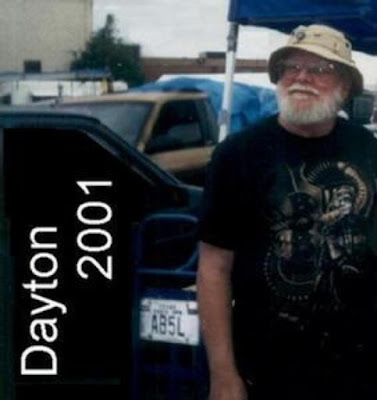
Summer Reading for Homebrewers: Frank Jones and the FMLA by Michael Hopkins AB5L (SK)

 
Frank Jones W6AJF (SK)

I read these stories when they were first coming out and I really liked them.  Here are all the FMLA episodes.  Don't try to read them all in one sitting.  Spread them out.  Savor them.  Think about the message that Frank was sending us.  

All of the FMLA episodes:  https://tomfhome.files.wordpress.com/2019/12/frank_and_the_fmla.pdf

--------------------------------------

Related articles, books and links: 

Frank's obit: https://www.pressdemocrat.com/article/news/frank-jones/

Frank's book "5 Meter Telephony": https://w5jgv.com/downloads/5-Meter%20Radiotelephony%20by%20Frank%20Jones.pdf 

Frank's 1937 Antenna Handbook: http://rfcec.com/RFCEC/Section-3%20-%20Fundamentals%20of%20RF%20Communication-Electronics/23%20-%20RADIO%20ENGINEERING%20DATA/1937%20-%20Jones%20Antenna%20Handbook%20(By%20Frank%20C.%20Jones).pdf

About the author, Michael Hopkins AB5L: https://www.rantechnology.com/index.cfm?key=view_resource&TransKey=615604E8-9DAA-40A3-9E48-4160806D893D&CategoryID=8E884CE4-9CED-4957-872B-5EBDB058D540&Small=1

Michael Hopkins AB5L (SK) 

Thanks to Dave Wilcox K8WPE for reminding us of all this, and for sending us the link to the FMLA archive. 

Viva el FMLA!   Viva el CBLA!  Vivan! 

The World's Largest Heathkit Collection (Video)


And this was apparently AFTER they relocated and organized things a bit. 

I have my eye on those QF-1s.  Someone stop me before it's too late.

I also spotted a Globe VFO Deluxe.  

Wednesday, June 30, 2021

10 Pole Crystal Filter Passband as Seen in Antuino and NanoVNA


I continue to work on the "Mythbuster" rig,  but I am taking it slow, trying to learn something from each stage.  I'm especially trying to master the used of the great test gear that has arrived in my shack in recent years:  The Antuino, the NanoVNA, and the TinySA.  

Above you can see the passband of the 10 pole crystal filter as measured across the 50 ohm terminations on the filter.  I use simple FT37-43 transformers to match the filter impedance down to 50 ohms.  I used the Antuino first -- it scanned the passband and held the image on its screen.  I then disconnected the Antuino and connected the NanoVNA.  So in this shot you can see the passband on both devices.  

You will notice that the Antuino says there is a 20db insertion loss.  That's only because in the Antuino 20db is really 0 db loss.  I think the NanoVNA gives a more accurate insertion loss reading -- about 3-5 db.  The cool thing is how similar the shapes of the passband are.  

Tuesday, June 29, 2021

Jack NG2E's Pebble Crusher


 Check out NG2E's Pebble Crusher homebrew transmitter.  Doug DeMaw would be enormously pleased.   

Jack will no-doubt have this 250 mW rig on the some peak along the Shenandoah Valley, handing out QSOs to SOTA fans.   

Jack's blog page has a really nice video on this project: 

https://jackhaefner.blogspot.com/2021/06/pebble-crusher-40m-xmtr.html

Saturday, June 26, 2021

SolderSmoke Podcast #231 -- Travel, SST, Mythbusting, Filters, TIAS, NanoVNAs, DC RX in SPRAT, Drake A Line, Spillsbury, STICKERS! Mailbag


SolderSmoke # 231 is available: 


Annual Field Day Special Edition

Travelogue:   To the Dominican Republic! 
New dog -- Meet Guapo (see below). 

A great Father's Day for Pete and Bill.  I got a TinySA. 
Pete got some cool chick magnet glasses (see below).  
Watch out Newbury Park! 


Bill's Activity

SST Transceiver. Took it to Dominican Republic.
Made only one contact, but QRP-QRP. 
Not a lot of CW activity, and not a lot around 14.060. 
A lot more FT8 visible on the NA5B WebSDR.
That might be better for this kind of operation.  
I might try SST CW out today from the backyard. Field Day!

Fired up my 20 meter DSB NE602 rigs.  Made two contacts.  
Still trying to fully understand the NE602 Gilbert Cell.  Lots of mystery in there. 

Building "The MythBuster."  75/20 with sideband inversion.  

10 pole 5.2 MHz filter.  Used Dishal and AADE. 
Used NanoVNA to see the passband. 
G3UUR for crystal parameters.
Cohn Constant K topology. 

Also used NanoVNA to check input and output impedance on the TIA amps I will use around the filter. 

Pete's activity: 

Article on DC receiver in SPRAT. FB response. 50 receivers under construction.   

Work on Drake A Line.  

Jim Spillsbury. 

------------------------------

The N5JHH IBEW SolderSmoke stickers (see above and below).  How we will use them. 

Mailbag:
N2SVD
K8ITY
Tom (Junkbox receiver)
N0ZIB (Curse you, SolderSmoke!) 
DL6ID
N2NLY
VK2EMU
ZS1KE
AF7O
NG2E
VU2ESE
OK1RP
N5JHH


Thursday, June 24, 2021

Radio Netherlands -- Bonaire Relay Station


Thanks to Rogier KJ6ETL, PA1ZZ for sharing this video with us (that's Rogier on the Vespa). 

I wonder what they did with the towers and the transmitters?  


Friday, June 18, 2021

Jean Shepherd on CW, and Strange Propagation -- QRP!


From 1965.  Great CW stories from Shep.  QRP!  Shep running 2 watts on 20 CW, working DX. 

He discusses shortwave listening,  and predicted that CW shortwave listening would become more popular (sorry about that Shep). 

It was real hoot to hear the 1965 public service ad from NYC Mayor John Lindsey. 

The Kazoo CW was a bit hard to copy OM. 


Thursday, June 17, 2021

The Stubborn Myth about USB and LSB

It  has been repeated so often and for so long that many of us have come to believe it.  I myself believed it for a while.   Like many myths, it has a ring of truth to it.  And it is a simple, convenient explanation for a complex question: 

Why do ham single sideband operators use LSB below 10 MHz, but USB above 10 MHz? 

Here is the standard (but WRONG) answer: 

In the early days of SSB, hams discovered that with a 9 MHz SSB generator and a VFO running around 5.2 MHz, they could easily reach both 75 meters and 20 meters (True). And because of sideband inversion, a 9 MHz LSB signal would emerge from the mixer as an LSB signal (True), while the 20 meter signal would emerge -- because of sideband inversion -- as a USB signal (FALSE!)  That sideband inversion for the 20 meter signal explains, they claim,  the LSB/USB convention we use to this day. 

Why this explanation is wrong: 

There is a very simple rule to determine if sideband inversion is taking place:  If you are subtracting the signal with the modulation FROM the signal without the modulation (the LO or VFO) you will have sideband inversion.  If not, you will NOT have sideband inversion.

So, you just have to ask yourself:   For either 20 or 75 are we SUBTRACTNG the Modulated signal (9 MHz) from the unmodulated signal (5.2 MHz)? 

For 75 meters we have:   9 MHz - 5.2 MHz =  3.8 MHz    NO.  We are not subtracting the modulated signal from the unmodulated signal.  There will NOT be sideband inversion. 

For 20 meters we have 9 MHz + 5.2 MHz = 14.2 MHz.     NO.  No subtraction here.  No sideband inversion.   

So it is just arithmetically impossible for there to be the kind of happy, easy, and convenient  USB/LSB situation described so persistently by the myth. 

---------------------------------

We discussed this several times on the podcast and in the blog: 

https://soldersmoke.blogspot.com/2015/05/sideband-inversion.html

https://soldersmoke.blogspot.com/2012/05/usblsb-urban-legend-debunked.html 

This myth shows up all over the place: 

We see the myth here: 

http://n4trb.com/AmateurRadio/Why%20The%20Sideband%20Convention%20-%20formatted.pdf

Here the web site owner warns that this is "highly controversial."  Really?  Arithmetic? 

http://9m2ar.com/lsb7.htm

The myth is very old.   Here is a clip from a 1966 issue of "73" magazine: 

https://worldradiohistory.com/Archive-DX/73-magazine/73-magazine-1966/73-magazine-01-january-1966.pdf

Finally, to my disappointment, I found the myth being circulated by the ARRL, in the 2002 ARRL Handbook page 12.3: 


The fact that the Handbook attributed this to a desire to "reduce circuit complexity" by not including a sideband switch should have set off alarms.  We are talking about hams who built their own SSB rigs, usually phasing rigs.  A sideband switch would not have added significant circuit complexity. I think they could have handled it. 

It is interesting that earlier ARRL Handbooks do not repeat this myth.  I found no sign of it in Handbooks from 1947, 1959, 1963, 1973, and 1980.  And I found no sign of it in several editions of that great ARRL book "Single Sideband for the Radio Amateur." 

For my next homebrew rig, I will build a rig that DOES do what the myth promises.  I will have the SSB generator running on 5.2 MHz USB.  The VFO (out of an old FT-101) will be running around 9 MHz.  So for 75 meters we WILL be subtracting the signal with the modulation from the signal without the modulation:   9 MHz - 5.2 MHz = 3.8 MHz.   There will be inversion.  This 75 meter signal will be LSB.   For 20 we will just add the 5.2 MHz USB signal to the 9 MHz  VFO.  There will be no inversion.  We will have a USB signal on 20.   I'm thinking of calling this new rig "The Legend." Or perhaps, "The Mythbuster." 

Tuesday, June 15, 2021

Hi Def 360 Degree Panorama from the Mars Perseverance Rover


Put this on full screen view and set for max Hi Def presentation. 

You can stop the video around the 1:10 mark, but then still use your mouse to pan around for a full look at the area (without the annoying labels that appear at the beginning).  
Designer: Douglas Bowman | Dimodifikasi oleh Abdul Munir Original Posting Rounders 3 Column