Astute aficionados (like Steve --Snort Rosin -- Smith) immediately recognized that I was talking rubbish when, in SolderSmoke 143, I said that the current LSB/USB convention on the HF bands has its origins in the FACT (not!) that when using a 9 MHz filter and a 5 MHz VFO, with a single carrier oscillator crystal you can very conveniently get USB on 20 and LSB on 75, supposedly because of "sideband inversion" that takes place when you switch from the sum product of the second mixer (20 meters) to the difference product (75 meters). I got out paper and pen and quickly discovered that Steve was right. No sideband inversion with this scheme.
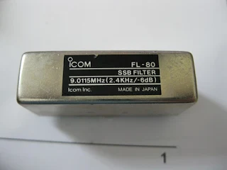
I was susceptible to this urban legend because when I was building my 17 meter SSB rig out in the Azores, I used a 5.174 MHz filter from an old Swan 240. I started out with a VXO running around 12.9 MHz, obviously using the sum output from that second mixer. Later, I decided to move the VXO up to around 23.3 MHz and take the difference product. Here I DID get a sideband inversion, and I had to go back to the carrier oscillator and change the crystal so as to get LSB coming out of the filter. When this 5.173 MHz LSB went to the second mixer, the sideband inversion took place and --Viola!-- 17 meter USB resulted.
The key factor here of course is that the VFO freq was now ABOVE the filter freq.
In the podcast I said that I "learned" about the alleged origins of the LSB/USB convention from the 2006 ARRL handbook. I had read it very quickly while in the local library. I don't think they would have gotten this wrong. It was probably my quick reading of the article that caused the rubbish talk.
Maybe it was this: Could it have been that in the early days of SSB, guys were using a 5 MHz FILTER with 9MHz VFOs? Maybe from old Command Set surplus gear? With the VFO above the filter freq you would get the sideband inversion that I was babbling about, right? Or might this have been the result of the phasing method of sideband generation popular back in the day?
Our book: "SolderSmoke -- Global Adventures in Wireless Electronics"
http://soldersmoke.com/book.htm
Our coffee mugs, T-Shirts, bumper stickers: http://www.cafepress.com/SolderSmoke
Our Book Store: http://astore.amazon.com/contracross-20

I have read in a Swedish magazine Resonans http://esr.se/resonans/ESR%20Resonans%203%202011.pdf on page 9 about this.
ReplyDeleteIn the early days of SSB they started at a very low frequency:
30 kHz LSB – 485 kHz oscillator
455 kHz USB – 4485 kHz oscillator
3990 kHz LSB
To get to 20m they used another IF after 455 kHz so it became USB.
The article has some references so I think you can go there for more info on this.
Eric SA5BKE
I wonder why is it conventional to use LSB for RTTY on 20m?
ReplyDelete