Podcasting since 2005! Listen to Latest SolderSmoke

Showing posts with label QRSS. Show all posts

Friday, June 26, 2009

VK5DGR's QRSS Rig

David, VK5DGR, built this very fine QRSS rig, and is currently shaking up the grabbers with 20 mW.

I really like his way of putting that power level in perspective:

"Look around your room and find a glowing LED. Well a typical red LED has 2V and 10mA flowing through it, or about 20mW. It can barely make it a few metres to be detected by your eyes. Imagine detecting it at a range of 1200km! That’s what I find remarkable about QRSS - tiny power levels that go a very long way."

For more info, go to David's "Beer, Coffee and a little DSP" blog:
http://www.rowetel.com/blog/?p=118

Friday, May 22, 2009

Tech Details on ET's "Phone Home" Beacon Rig

Mark "MOJ" Johnson, W8MOJ, sent me a really amazing 73 Magazine article. It is from the APRIL 1983 issue. (The month of publication set off my April-fool alert alarm, but this is for real.) When Steven Spielberg was making ET, the producers contacted Bell Labs and asked for help in designing the rig that ET would use to phone home. A ham, Henry Feinberg, K2SSQ, got the job. In the article, Henry wrote: "What Spielberg wanted was a beacon transmitter, something to say, 'Here I am, Come and get me!' I reasoned that three main parts wee needed for a basic beacon: a means of producing a message, a programmer to repeat the message, and a way of transmitting the signal into outer space."

Later, in describing the keying device, Henry wrote: " The surface of the saw blade was coated with several layers of spray paint, which served as insulation, preventing the bobby pins from contacting the metal blade. The message was programmed on the blade by carefully etching through the paint. "

OK, that does it. Time for me to go back to the Trastevere flea market to pick up some more cheap clock drives... and maybe some circular saw blades. I need to get going on my mechanical QRSS one-transistor becaon project.

Saturday, April 25, 2009

Eldon's awesome 9V QRSS rig

Amazing! That's the whole rig, keyer chip included! And those red wires you see coming off the end -- that's the loop antenna. Here is Eldon's description of this rig:

For now, even thou it worked, I have abandoned the Water Tank QRSS Encoder, for a more traditional ID Keyer (K-ID2), and I have been busy rebuilding my 9 Volt Battery QRSS transmitter.

For my first approach, I wanted to use the Manhattan style of construction using mostly SMDs. The Oscillator was very successful even thou there were NO actual Manhattan Islands use, the components are just tacked-soldered together - I guess it would have to be called the "Ugly SMD Style".

Photos of Rev-0 are available on my web site;
http://qrss.ebcon.com/WA0UtWH/Gallery/Qx/

Setting the frequency was tough, as the some initial installed component's had to be replaced to get it to oscillate and adjustable within the 100Hz QRSS band. The "Ugly SMD Style" of construction is possible, but circuit changes are difficult. I decided to etch a HB circuit board to provide for a more physically stable "component selection breadboard", where SMDs part values could be easily tried, by just pressing them down in place (which BTW works very well). I then decided to expand the etched board to include space for the K-ID2 Keyer - with the goal of direct QRSS modulation with very few additional components.

This all worked so well, that I constructed another for a final form. Note: the second transistor in the photos is a 78L05 voltage regulator, which is used to help with long term oscillator stabilization, and used to reduce the power requirement and provide battery longevity.

The final QRSS Beacon uses a SMD 2N3904 for the oscillator and is now transmitting 1.5mW into a 18 inch loop antenna, currently only my grabber shows the results. But - My plan is to build this Beacon into the center insulator of a 30m Dipole and then start looking for QRSS Grabber DX. The battery should last several days at this very low power.

My goal is: to achieve long distance, with a very physically-small transmitter, small part count, and with extremely low power.

It will take me several days to construct and install the dipole antenna, until then you can see this Beacon sending "WA0UWH" on the Seattle Grabber:

http://qrss.ebcon.com/WA0UtWH/grabber/

73's - Eldon - WA0UWH

Friday, April 10, 2009

Parachutes and QRSS

Kevin, AA7YQ, has made innovative use of a parachute. You are right Kevin, this must be a first:

Howdy Bill,
It’s Kevin here in Montana, the ex-Smokejumper. I’ve been meaning to write again. Thanks for the nice comment on SS #100 I got a kick out of it. Anyhow, just thought I’d drop you a note to let you know I finally had a weekend to design and build up a QRSS beacon. I used a Cypress PSoC CY24123A uC to function as the Crystal Oscillator, and keyer. The final is two paralleled BS-170 MOSFETs running in Class-E mode to give me about 560mW out with a 7.5volt Lantern battery as my supply, total system power efficiency is about 63%(RFout over DC in), I’m sure this could be significantly improved, but good enough for now. After several hours of tweaking the capacitor values I finally got the oscillator to fall into the 100Hz window. That was MUCH harder than I had anticipated. With the original version I switched the PA on and off for true QRSS 3 CW, but found this made a significant frequency drift problem. So I added a couple parts and modified the PSoC code a bit, now its running CWFSK, switching about 1.1pF on and off one leg of the XTAL, shifting the frequency about 10Hz and much more stable.

My first tests were with the board sitting on the bench under the desk lamp. This caused all kinds of drift problems. I then put the beacon in a Tupperware container and placed it inside a soft case cooler. I was looking around the shack for a blanket or something to further improve the insulation, when low and behold sitting in a garbage sack… was a condemned FS-14 parachute (equivalent to the SF-10A) that I was planning using for something useful. So I wrapped the chute around the cooler and stuffed it all back in the garbage sack. Surprisingly, temperature stabilization was achieved, beyond my expectations.

The beacon is running good now, nice and stable. I’m fairly certain, that in the history of mankind, no one has ever used a parachute to improve the temperature drift characteristics of a QRSS beacon. Anyhow, I plan on having it fired up quite a bit, so that my antenna is actually put to some good use. It seems I rarely get a chance for one to one contacts anymore. Most of my free time is spent designing and building the radios I never use. Ha. I guess the design and building is the real fun for me.

Anyhow, I’ll talk to you later. 73s Kevin, AA7YQ

PS the Beacon is sending “AA7YQ” followed by a several second pause. It’s showing up on the K6HX grabber between 10.140050 and 10.140060.

Wednesday, March 18, 2009

Eldon's Acquatic "ET PHONE HOME!" Machine

Man, the authorities would DEFINITELY blow this thing up if they found it! Check out Eldon's innovative effort to keep the transistor count to ONE and to use mechanical means to generate his QRSS callsign. "COMING SOON TO A GRABBER NEAR YOU!"

Here is the e-mail from Eldon describing his creation. Using the saw blade was a nice touch!

Bill, In keeping with the spirit of QRP, QRSS and the minimalist HB challenge of ET-Phone-Home I have enlisted one of my single-transistor-nine-volt (2N3904) QRP rigs. With the best that I can measure, this system has a DC "input power" of 6.84mw into a 16 inch loop antenna of 30 AWG copper coated-steel MIG welding wire. On previous experiments, the Tx was easily detected from 1500 feet away from on my grabber. Longer DX experiments have not yet been conducted. Note as per the photos, I have cheated a little, the Tx rig that I selected to used, was from a previous project, and has an additional active element, a five volt regulator (LM7805) for oscillator stability and battery longevity (i.e the 9 volt battery voltage can decrease down to 7 volts and oscillator requires only 1.8ma before the Tx frequency goes unstable). Bill, The QRSS frequency modulation technique that I used is the same that I suggested for you to invert your FSK MEPT transmitter signal - for up frequency modulation - increase the "capacitance to ground at the collector" of the oscillator ( which I think cancels some of the normal colpitts crystal oscillator capacitance - and therefore the frequency goes up with increased capacitance ). My modulation requirement does not need a "gimmick" as you have used, because of my use of direct mechanical capacitance coupling (as described below). For modulation my system uses about 8 gallons of water in a 6 inch reservoir with trickle flow bypass regulation around a weighted falling piston, which pulls on a string, which turns the encoder. The piston is large "Whole Fancy Indian - Cashew - Premium Quality, All Natural" nut container ( obtainable from the actual Kirkland Costco store ) with Velcro (loops) Sticky tape wrapped around the top and bottom bulges providing the snug fit and trickle flow metering in the water column. About 8 lbs of weight was added to the nut container to provide the necessary potential-energy storage. This system of metering and energy storage provides for a run-time of about 10 minutes, before a mechanical reset is necessary ( note to potential builders, performance and timing formulas are not included within this document ). Following ET's example, the encoder is a 10 inch multi-cut rotating disk encoder - model number 9-32636 (only obtainable from Sears) augmented with "replaceable-movable-removable" coding elements attached with tape. Before the coding elements were installed on the modulation encoder, the system produce a QRSS "Saw Tooth" waveform (what else would you have expected?), which was initially used just for testing (see: the additional oscillator mounting hole on the substrate, closer to the pivot point ). Note, this encoder technique requires no actual physical or switch contact with the Tx. Only a ground and collector capacitor plates were extended from the colpitts oscillator to form the modulation active elements. I originally was planning to encode my own call - "WA0UWH", but the encoder blade could not hold that much data. A blade upgrade is being considered (i.e., 12 inch). For now, I have chosen something shorter and simpler to encode (as ET would have suggested), I will use my QTH as the name of the nearest major landing-site in my area with high intensity approach lights - SEA (Seattle International Airport), besides it was much easier to cut from PC stock - 5 dots and a dash. Note: the selected message can be shortened by folding the unused elements onto the center of the modulation blade (Note to self - other messages could be encode using the same elements and a similar folding technique, that is "ET" could be encode from the "SEA" elements ). The resulting modulation is not as square as traditional QRSS3 digital driven keyers, but, . . . it is very distinctive. The FIRST major modification to this system was the addition of a rolling cart for transport, I had to move the reservoir to a stairs where I could get above it, to pull up and reset the modulator piston, which by the way requires about a 20 lb pull for about the same duration as the run time (about 10 minutes). The NEXT major modification WILL BE a maximum flow (3/4 inch) tickle flow "bypass" pipe via a control "valve" to aid in the reset process ( for the European critics, I do not think this should be mistaken nor counted as an active QRP element ). This will make the resetting process go much smother, quicker, and should require much less external "arm strong" input power (question: where does the input power go?? warming the water??). The MEPT QRSS operation is simple; Raise the piston (lock it in place), Wind up the draw string around the pulley, Install the encoder disk, Release the lock, and then Wait for the DX grabber reports? Note: a complete set of construction, operation photos and grabber images will be added to my Gallery when time permits: http://qrss.ebcon.com/WA0UWH/Photos/ NOTE: For others HB'ers interested in this project, Kits WILL NOT be made available. Bill, watch for my signal on the 30M grabbers - it should be very recognizable as my signal will have a bit of a "Saw Tooth", waveform component. More details may follow as the project progresses (to where, I am not sure, but I do know that this is enough of this!). Bill, It has been fun !! 73's - Eldon - WA0UWH - alias "SEA" Phone Home BTW: No actual grabbers were harmed while collecting data for this document, but a 30db attenuator was added to the antenna connection on my SA602 DC receiver for its near field overload input protection.

Tuesday, March 17, 2009

Mechanical Memory Keyers

Billy and I went to the Rome flea market this Sunday and picked up a clock motor that may become the core of a mechanical keyer for the single transistor QRSS MEPT beacon we've been talking about. Unfortunately ours is battery powered -- we couldn't find any wind-ups that had a second hand.

I got an intersting e-mail on this subject from Gene, K8EE:

Mechanical Memory Keyer

Monday, March 16, 2009 6:44 PM
From:
To:
n2cqr@yahoo.com

Hi Bill,
Just wanted to let you know that I built a mechanical memory keyer
back around 1960. It was very similar to the one you suggested in the
last "Solder Smoke." I built it for the radio club to use on Field Day. It
It used a phonograph motor to coupled to a mechanical variable speed
drive
. A circular piece of PC board was attached to the output of the
VS drive. Patterns were etched on the PC board for the CW
messages, one to call CQ, one for the contest exchange and one to say
"tnx QRZ ...."

Of course, the variable speed can be achieved with a D.C. motor instead of
the mechanical VS drive. Todays computer software can create much
better artwork to etch on the PC board.

Unfortunately, I threw the thing out in the trash a couple of months ago. I
wish I still had it so that I could send you a picture of it. Oh well. What's
done is done.

Tell the guys that it CAN be done and it HAS been done.

73,
Gene Mayler - K8EE

Friday, March 13, 2009

G3ZJO: QRSS WIZARD!

Well, we're the Knights, right? So we should have a few wizards. Eddie, G3ZJO, should certainly be among those so honored. Above you can see his "G Beacon" MEPT transmitter. He uses two 555 chips to generate the G letter in Morse code. The longer chip on the bottom is (I think) the RF part of the transmitter. Ingenious. I also like his selection of frequency: 10140073 Hz. FB.

Eddie has a lot of other tricks up his sleeve, including the use of a Voltage Controlled Variable Oscillator driven by a PIC chip for a very simple WSPR transmitter.

These and other inventions can be seen on Eddie's YouTube page:
http://www.youtube.com/user/g3zjo (most seem to be done without audio).

Also check out his QRSS Beacon web page:
http://www.g3zjo.talktalk.net/qrss.htm

Thanks Eddie

Wednesday, March 11, 2009

Heavens Above

So I'm sitting there at 5:30 am talking on Echolink to Jerry, NR5A, in South Dakota about his ailing Pixie soon-to-be QRSS transmitter. All the talk about getting on the air and emitting signals causes me to get the urge to fix my antenna.

On Monday, I'd noticed (via Blackberry) that my signal had disappeared from ON5EX's grabber. I could see a signal close to where I usually am, but it looked a bit different. On closer inspection I saw that EA6FNF had fired up a very nice 50 mw DFCW beacon on around 10140060 Hz. My signal was gone. When I got home I discovered a broken antenna wire. Once again, ON5EX and the internet had, in effect, relayed telemetry about the status of my QRSS system.

Fortunately I could fix this from the window -- no roof work was required. Skies were fairly clear on Wednesday morning, and as I looked up across the Janiculum Hill at Rome's pre-dawn sky, I saw a satellite going over from North to South. Of course, I wanted to know what I was looking at, so I turned to Chris Peat's very useful web site, Heavens Above. Very quickly, I was able to find out that it was either the Russian Okean O Rocket, or something called RADCAT.

Check out Heavens Above. Lots of great info on astronomy, satellites, and ham radio spacecraft:
http://www.heavens-above.com/

The antenna was quickly fixed. I should be back on the Belgian grabber now. It was a good ham radio morning in Rome. Thanks Jerry. Thanks Chris Peat.

Sunday, March 8, 2009

Clockwork CW: The Path to Minimalist QRSS?


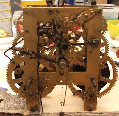
Well, maybe not using that one. But something like it. The idea -- mentioned recently on the podcast -- is to use a mechanical clock mechanism to generate the CW for a QRSS beacon. This would allow us to get the transistor count for our beacon down to one. For some odd reason, some of us find this appealing, especially when you consider that the transistor count on the receive side is in the tens or hundreds of millions. One is the magic number. You can see how this project brings together two of the biggest littlest recent trends in the QRP radio: QRSS and minimalist radio.
It's kind of scary when you Google something and are referred back to your own blog. That's what happened to me on this subject. Back on May 28, 2008, this was posted (by me!) as a comment to one of the beacon-related posts:

Hello Bill and Others:

A few years ago, a buddy had made a neat keying operation made by taking a
one RPM clock motor and had it rotate a printed circuit board disk that had
the callsign etched on it several times sequentially. Clock motors are
made to run continuously for years, and it stood up with just an
occaisional cleaning of the wiper arm with spray cleaner.
All the best to all!
73 de Lee Smith VE4ANC

This message from Lee was a response to a January 1999 question from me. So we are sort of re-inventing the wheel here.

Of course, there are some QRSS beacon circuits out there with VERY low transistor counts. Hans Summers has one on his site that used a bi-stable multivibrator to generate a pattern for QRSS. That would yield a total transistor count of 2 or 3. But we are going for one single transistor. And I kind think we should look for something that will allow for the transmission of callsigns.

Here's an e-mail exchange from the Knights of QRSS mailing list that may generate some ideas:

Re: [Knightsqrss] Junkbox + soldersmoke = pattern generator

Saturday, March 7, 2009 10:43 AM
From:
To:"n2cqr"

Very nice idea Bill. After tiny solar mepts this could been our next QRPP/ET challenge .
73 de Paolo IZ1KXQ
--------- Initial Header -----------

From : knightsqrss-bounces@cnts.be
To : knightsqrss@cnts.be,"Soeren Straarup" xride@x12.dk
Date : Fri, 6 Mar 2009 21:48:55 -0800 (PST)
Subject : Re: [Knightsqrss] Junkbox + soldersmoke = pattern generator
It would be fun if the clock were a "wind up" type. And for extra credit: Power the transmitter with the energy from the same spring mechanism (or other wind-up device) that powers the clock!
ET PHONE HOME!
--- On Fri, 3/6/09, Soeren Straarup <xride@x12.dk> wrote:

From: Soeren Straarup <xride@x12.dk>
Subject: [Knightsqrss] Junkbox + soldersmoke = pattern generator
To: knightsqrss@cnts.be
Date: Friday, March 6, 2009, 3:30 PM
Hi list,
Hans Summers has made an astable multivibrator as pattern
generator.
Bill Meara has thought about making a analog clock.
Alan Yates loves my idea of an exercise bike pattern
generator.
Though i'm open for suggestions. No pics, pc or
any other programmable
devices.

Rules of design:
1) KISS
2) Should be in most junk boxes
3) Pattern should be easily changed (diversity, more
homebrewers)
4) KISS
This is for a simple Pixie2 TX modified to be a QRSs TX.
Stability? SSShhh.
Vy 73 de OZ2DAK
Soeren Straarup | aka OZ2DAK aka Xride

Wednesday, March 4, 2009

Italians at the Forefront of QRSS

In SolderSmoke 102 I mentioned that Italians are playing an important role in QRSS. Alberto, I2PHD, is certainly one of the key people. His software is behind most of the grabbers that we all use. THANKS ALBERTO! Here's his bio:

Born in 1944, in Lucca, Tuscany, Italy. Got a Doctorate Degree in Physics at the University of Pisa. Since then worked for IBM, with various responsibilities. Radioamateur since 1966, active on most bands, from 160m to 23cm. Lately experimenting with 137 kHz, recently allowed in Italy with 1W ERP.

Studying and applying DSP and digital techniques in general. Author of Winrad, SDRadio, Spectran, Jason, Argo and Hamview, widely diffused programs for SDR (Software Defined Radio), spectral analysis and real time filtering of audio signals, received with a radio and routed to a PC equipped with a soundcard.

Despite the age, open to learn new techniques and theories. *Not* a tube (or valve, depending on the side of pond you are reading this) nostalgic.

73 Alberto, I2PHD

Home page http://www.weaksignals.com

ET Phone Home! With Minimalist QRSS!

I knew that Alan Yates, VK2ZAY, was just the man for this project. Alan and I met up several years ago when Billy and I spotted and built his Trivial Electric Motor (we still have it, and occasionally fire it up to amaze visitors). On SolderSmoke 102 I mentioned the possibility of a one transistor QRSS transmit station. Obviously this would require some sort of mechanical keyer. I thought of a clock drive. Alan pointed out the in the 1982 Steven Spielberg movie, ET had used a saw blade as his mechanical modulator (see above). Alan also had some intriguing ideas of his own:

G'day Bill,
Thanks again for noticing my QRSS signal making it through to Europe.

Your talk about mechanical solutions for QRSS modulators immediately

made me recall "E.T. the Extra-Terrestrial". The "Phone Home" device he
built had a modulator based on a sawblade IIRC - its been years since I
watched that 1982 classic.

One easy hack might be to use an AC synchronous motor out of a gobo
rotator (for example, I got one out of a fibre optic christmas tree that
expired from overheating). Its reduction drive results in a fairly slow
rotation which might drive a modulator plate. You could do the pickup
optically using a LED/photodiode (or transistor, or even an LDR I guess)
transmission pair. Electrical contacts would work too, but doing it
optically probably means it would have a longer life.

A tape loop system might also be practical and would allow long
modulations to be encoded at reasonable tape rates. A syncro-drive gobo
has to be turned fairly slowly and pushes the "density" of the data
fairly high so the mechanical or optical sensor gets harder to just
throw together. I am sure a clockwork driven disk could be made to
work, it just might have to be fairly large.

Mechanical readout might be a microswitch and holes in the plate, or
even using PCB material with the pattern on it (etched or masked), and a
brush contact. To minimise wear a brass small roller held against disk
with spring tension would work. Oxidation on aging might become a
problem - yeah the more I think about it I am liking optical better.

You can also do it electrically using a diode matrix which can be read
out with some counters. Of course that defeats the original purpose
which was to make a single transistor QRSS beacon with a mechanical
modulator.

One completely insane idea that just occurred to me is to build a slow
mechanical oscillator (say driven by a Stirling Engine or a Curie Point
Pendulum heated by a small candle) and modulate the RF oscillator with
that. The mechanics or thermal system might directly effect the RF
oscillator frequency. Who will make the first candle-powered QRSS
beacon with thermopile PSU? :-)

Regards,
Alan
http://www.vk2zay.net/

Wednesday, February 18, 2009

WA5DJJ's QRSS Beacon: Immediate Success!

Here's a story that really captures the fun of QRSS, the way in which this mode can be both high tech/DSP-ish and low tech/minimalist at the same time. It also shows the global reach of the fraternity that supports QRSS. In SolderSmoke 101 I reported on the QRSS building project of Dave, Wa5DJJ. He was building a rig based on a design by the esteemed Maltese radio wizard Stan, 9H1LO (Stan appears in the SolderSmoke slide show -- he is the guy in the lab coat.) You'll recall Dave's comment on how upside down FSK might be useful in reaching our brothers "down under." Yesterday Dave put his new creation (see above) on the air, and posted a message to the Knights of QRSS Yahoo Group. In Belgium, Johan, ON5EX, saw Dave's message and decided to check W8LIW's receiver (via LIW's online grabber). Johan saw Dave's signal and reported the success to the Knights.
You can read more about Dave's project here:
http://www.zianet.com/dhassall/QRSS.html

Here is the e-mail exchange between Dave and Johan:


Tuesday, February 17, 2009 7:46 PM
From:
To:
knightsqrss@cnts.be

Hi Dave, I can see your sigs are on the Ohio W8LIW grabber right now, with a little downward shifting. Well done! Your website truly reveals a keen QRP-er and homebrewer. BTW: I’ll be firing up my first RockMite (20) soon! 73, Johan on5ex


From: knightsqrss-bounces@cnts.be [mailto:knightsqrss-bounces@cnts.be] On Behalf Of David R. Hassall
Sent: woensdag 18 februari 2009 1:30
To: knights QRSS
Subject: [Knightsqrss] WA5DJJ on the air!!

Dear Gang,

First test of my QRSS 10.140Mhz MEPT. It should be around 1.060 on the waterfall. Power output is 122mW (All I could squeeze out of my poor little 2N222A final. Keying is up shift, at about 5 hz. I hooked it to my 30 Meter Inverted Vee off my tower. Apex is at 40 feet. I think I have it right and hope it doesn't blow up. We shall see when I get some reports. I will have pictures on my website as soon as I can get them there. Thanks for all the advice and help. This was a really fun project. Now to get a couple more built to get some others on the air.

73 Dave

------------------
BTW: I succeeded in putting Johan's grabber output onto this blog. Look at top of my right-hand column. If the sun is up over Europe, you should see my upside down FSK around the middle of Johan's screen. (He has the screen kind of split in two to allow more minutes to be displayed, so you should see me in the middle of both the top and bottom halves of the screen. ) You may have to hit the refresh button on your browser to get my blog page to pull down an update of Johan's grabber. Just think about how cool this all is: I transmit a 50 mw sig from Rome with a very minimalist rig. Johan receives it in Belgium using DSP software and puts the results on the www. I embed his output screen on my blog, which you can now see, almost in real time!

Tuesday, January 20, 2009

The Power of QRPp with QRSS (very low power, very low speed)

Here is a screen-shot taken in New Zealand back in 2006 (ah, the good old days, back when we still had a few sunspots). Colin, G6AVK, describes what you are seeing:

Hi Knights,
Whilst looking through some 30m captures this evening I thought it good to
share this with you, the Capture was from Mike ZL4OL back in early 2006.

Stations in this Capture listed from Top to bottom:
(675) G6AVK JO01HO sawtooth, 10mW into the Longwire.
(660) I0SKK JN61GV 25-30 mW max. Vertical R7 30 m high (on the top of the
roof)
(635) G0UPL 360mW. Antenna: full size half-wave dipole (14.2m) in the Attic.
(620) IW0HK JN61FV, 20mW's, Antenna used was a "Fishing Rod" vertical, 7.5
meter high.
I am looking forward to when Condx will be like this again.
73 Colin
G6AVK - JO01ho

Wednesday, January 14, 2009

Eldon's Beacon: GRABBED!

Last week we put out an all points bulletin for the new QRSS beacon of OM Eldon (scroll down a bit). Yesterday the signal was captured by Stu. Distance covered: 723 miles. Eldon's power out: 15 milliwatts. That's correct: fifteen milliwatts (Eldon had earlier calculated 150 milliwatts, but this turned out to be incorrect). Above is Stu's screen shot -- you can see Eldon's FSK signal: WAOUWH (read along the top of the square wave) at around 10140050 Hz.

Here is their e-mail exchange:

Re: Is this your QRSS beacon?
Tuesday, January 13, 2009 6:17 PM
From:
"Eldon"
To:
"Stu"
Thanks Stu, and thanks to Bill Meara and SolderSmoke.com
This is my my FIRST confirmed QRSS report from my first QRP rig, it is about 150mw into a North South 6 foot Loop about 6 feet AGL.
You represent it on about the freq that I think it is - without too much calibration on my part.
See: http://qth.map.googlepages.com/?qth=CN97BV43TU&from=CM87vk
Is your Grabber online?
Thanks for the report.
Regards, Eldon Brown - WA0UWH
Don't let the Zero land call fool you, I got it many year ago while in the Navy stationed at Denver, now located in Seven land near Seattle.
eldonb@ebcon.com

On Tue, Jan 13, 2009 at 12:39 PM, Stu wrote:
Eldon,
Copied the following screen shot on 30m today a few minutes ago – I think the FSK is your callsign – WA0UWH?
Copied with Spectrum Lab in CM87vk – TS-B2000 with 160m inverted L plus antenna tuner to load up on 30m
73's
Stu

Saturday, January 10, 2009

The QRSS Calibration Problem: A Proposal

Eldon's effort to be seen by the 30 meter online grabbers (see below) reminded me of the big problem I faced when I first built my QRSS beacon: getting my signal into the very narrow (100 Hz wide) QRSS frequency band. If you think crystal control will solve this problem, think again: Almost all of us are using crystal-controlled transmitters, but circuit and component variations can easily put your signal far outside the freq range that the grabbers are watching.

I was able to get into the band because I was able to find a conventional CW beacon fairly close in frequency to the QRSS band. I used IK3NWX on 10.141800 MHz. Knowing the frequency of this beacon (it was avalable on the web), I used the ARGO and Spectran soundcard programs to put my sigs where I wanted them to be. IK3NWX was useful because it was so close (within 2 Khz) to the QRSS band -- I was able to put both the NWX signal, and my target freq on the screen. Later, I built my "DaVinci Code" reference oscillator -- it serves as a freq reference that I can use (again, with Spectran) to get back in the band after working on my transmitter (for those times in which I can't hear IK3NWX).

It seems like a lot of guys in the US and Canada are now getting into QRSS. Many may face the same frequency calibration problem. Are the frequency readouts of the ubiquitous Kenwood/Icom/Yaesu rigs accurate enough to help? Do they go down to the tens of hertz range? I suspect they do not.

What new QRSS ops in the U.S. and Canada might need is the North American equivalent of IK3NWX's beacon. It should probably be fairly high powered (but 5 watts would probably do the trick). Conventional CW would be better than QRSS (it needs to be heard). The frequency should be outside but within 1-2 kHz of the upper or lower QRSS band edge. A station out in the Great Plains would probably be able to serve the large ham populations of both coasts. Perhaps we could arrange for the calibration beacon to be on at certain times (daytime on the weekends?). Of course, the key would be to employ a station with very accurate frequency measurement ability (down to 1 Hz) and a highly stable signal.

What do you guys think?

Friday, January 9, 2009

Eldon's QRSS Rig

Eldon, WA0UWH, says the podcast inspired him to build some QRSS transmitters for 30 meters. His first effort was atop a 9 volt battery. The latest version has a more traditional enclosure. Eldon hopes to be seen on some of the grabbers -- please help him out if you can. In my case the hard part was getting the transmitter into the frequency band for QRSS (only 100 Hz wide!).

Friday, October 31, 2008

See if you can see my signal 10140055 Hz

If Italy is in daylight, you should be able to see my 50 milliwatt FSK signal on one of the European on-line grabbers.

IK0VVE has a nice grabber aggregator site that includes a sun clock. Here it is:
http://www.ik0vve.net/mept6.aspx

Just see if the sun is shining here, then scroll down and take a look at either PA1SBD's site or ON5EX's. Sometimes I can also be seen on I2NDT's.

You should see my signal around 10140055 Hz. It looks kind of like a square wave. Read the Morse along the bottom (my FSK is upside down).

For extra credit, see if you can see Paolo's solar beacon. It too looks like a square wave, but with no Morse. He's running 2.5 milliwatts.

Please let me know if you succeed in seeing our sigs.

Tuesday, October 14, 2008

The Da Vinci QRSS Code

Here is my 30 meter QRSS frequency standard using paper for insulation.

Sunday, October 5, 2008

I SHIFT TO FSK ON 30 METER QRSS

The online grabber of Johan, ON5EX, provided instant gratification this morning. Right after I finished some modifications that I hoped would result in a Frequency Shift Keying signal on the 30 meter visual QRSS band, looked at the grabbers and found this. That's me. It is a kind of "upside down" FSK. Look along the bottom of the square wave and you can read the CW.

I used a fairly standard approach to get the FSK, but with a twist: I added the usual LED and a cap to the oscillator circuit. Now, on key down, the positive voltage from the keyer causes the LED to conduct, putting the additional cap into the circuit. But here is the twist: for the capacitor, I just used some of that twisted-up two conductor insulated wire that often comes with cheap old (mono) ear phones. In the old days this would have been called a "gimmick" capacitor. I started out with 3 or four inches. Using Spectran to monitor the amount of shift, I just cut off bits of the wire until the shift was at the desired 5 Hertz. I just clipped away at the wire until the shift looked about right.

The rig is now key down all the time, and even though power out is still only about 20 miliwatts, I have the final in Class A, so I actually had to put a heat sink on it. But there is still no need for a muffin fan, or liquid cooling or anything like that!

Five hertz isn't much of a shift. I think I can hear it, but barely. Shows up nicely on the grabber screens.

It was a lot of fun to start out with a vision of what I wanted the signal to look like, then actually make it happen.

Thursday, September 25, 2008

IZ1KXQ's Wind-Powered QRSS Beacon

Paolo, IZ1KXQ, is the fellow who brought us the 5 mw QRSS MEPT beacon powered by small solar cells (see an earlier blog entry). He is now experimenting with wind power. FB Paolo! We hope to see your windy signals soon.
Designer: Douglas Bowman | Dimodifikasi oleh Abdul Munir Original Posting Rounders 3 Column