Podcasting since 2005! Listen to Latest SolderSmoke

Showing posts with label UK. Show all posts

Thursday, March 12, 2020

Thoughts on How Hams Can Use the Shortwave Broadcast Frequencies


Ed DD5LP sent us some very interesting information about a resurgence of shortwave broadcast activity in Europe.  Thanks Ed. 

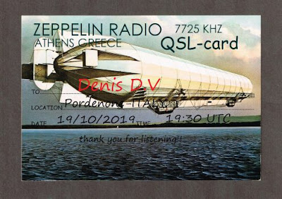
Here is a collection of QSL cards sent out last year by some of these new stations.  

Hi Bill,

I'm just listening to the latest podcast and note your returning lovefor AM Broadcast stations and wondered if you also see the trend in the US that we are seeing in Germany?

 I know you have WTWW but that's a commercial SW AM Broadcast radio station, that has always been owned and run by a family of Hams. What we are seeing Germany is that when a commercial broadcaster such as Deutsche Welle closes down their Shortwave Broadcast stations, Amateurs are applying for and getting licences to the freed up frequencies. This started about 5 years ago with channel292 (Channel292.de) on initially 6070 kHz and then later also  on 7440 kHz. This amateur is located near Ingolstadt in Bavaria and runs 10 kW using the driver stage from the old DeutscheWelle 100 kW transmitter on the same frequency. He is partnered with a group in Austria who run a major AM station near Vienna that has two 500 kW transmitters and some fantastic massive antenna systems with 20dB gain across the whole  of the HF spectrum. That Austrian station is still owned by the Austrian government in case they need a broadcast station to transmit around the world at any time. It's kept "idling" at 100 kW in the meantime and like Channel 292 includes the German language "DARC Radio" amateur radio program in what it transmits.

New on the scene is "shortwaveradio.de" - Yes the station name is the same as their web address. They currently run just 1 kW into an Inverted-V wire antenna on 3975 kHz (in the 75m BROADCAST band over here) and 6160 kHz in the 49m broadcast band.  As they are located in North Germany, I don't get much of a signal from them down here in the south and the recording is using a WebSDR receiver. Their dipole is orientated to cover the Benelux countries and the UK. The lads at this station are always looking for English content, so if you want part of Soldersmoke to be transmitted on a shortwave AM broadcast station, (as you mentioned in the latest podcast) I can easily put you in touch with them.

One more for the list could be Radio Caroline in the UK. The station, which once was the main pirate radio station off the coast of the UK is now a volunteer historic preservation society (with some radio Hams involved) who have been granted a local radio service licence using a frequency (648 kHz) and transmitter site previously used by the BBC world service! Their old nemesis ! (http://www.radiocaroline.co.uk/#home.html )

73  Ed DD5LP / G8GLM / VK2JI.


Thursday, March 5, 2020

Boat Knack -- Rebuilding a 1910 yacht "Tally Ho"

https://www.youtube.com/channel/UCg-_lYeV8hBnDSay7nmphUA

I present this as part of our occasional series on people with other kinds of Knack.  The young Englishman in this series of videos is definitely in this category.  Watch him acquire the 1910 yacht "Tally Ho" for 1 pound sterling, transport it to Washington state,  SINGLE HANDEDLY  build a boat shed around the huge vessel, and carry out the restoration.  Oh yea, all the while shooting videos of his work. Great stuff.  

I advise you to watch the series from the beginning.   The next video in the series will load automatically. 

Be sure to subscribe the channel. 

Thanks to Ryan Flowers of https://miscdotgeek.com/ for alerting us to this. 


Saturday, November 9, 2019

SPRAT, the FETer, DLR headphones, and recent QSOs on the ET-2


Yesterday we had QSO #13 on the ET-2.  This was with Jim W1PID.  In an earlier contact Jim told me I had some chirp.  I fiddled with the coupling cap and the bias pot and am now T9!  These days, chirp is an endearing, nostalgic problem to have.  Thanks for the report and QSOs Jim! 

Contact #9 was with Fred K9SO.  He is in Wisconsin and QRZ.com put our distance at 633 miles.  That is our DX record so far.  Not bad for 92 milliwatts to a dipole on 40 meters. 

Most of my contacts come as a result of pleas for assistance on DX Summit or the SKCC Sked page.   But I did make one "random" contact: Contact #6 with N2VGA.  He just heard my CQ and gave me a call.  FB. 

I checked to see if OM Glen Yingling W2UW -- the guy who started all this with his ET-1 -- is still around.  He became a silent key in 2012.  But his ideas live on... 

SPRAT 137 (Winter 2008/09) has a great article by QRP hero G3XBM.  Roger built a version of the ET-1.  His was for 80 meters and he called it the FETer.   FB.   I was struck by his estimate of the sensitivity of the ET-1 receiver: -100 dbm.   I measured the N0WVA receiver (the one that I am using) has having a minimum discernible signal of -93 dbm.  Pretty close.  We may be at the limit of what you can expect from a single transistor receiver. 

SPRAT 137 had something else that really resonated with me.  G3YVF had an article on a minimalist rig using only one 6V6 tube.  Geoff opened the article with this warning "Don't try this unless you have a set of balanced armature type DLR 'phones as they are really sensitive."  I have a collection of old headphones that I picked up at hamfests in London years ago.  When building the ET-2, I checked all the old phones for sensitivity.  A set marked DLR was the most sensitive.  So Geoff's observation had been independently confirmed.   QRP Quarterly had an article comparing the sensitivities of old headphones -- we should dig that article up.   

SPRAT #137 is a reminder of what a great resource SPRAT -- The Journal of the GQRP Club -- really is.  As we say on SolderSmoke, if you are not a SPRAT subscriber you are just wrong!  Here is how to join GQRP and subscribe to SPRAT: http://www.gqrp.com/join.htm

Saturday, May 4, 2019

SDR vs. HDR - Is the Superhet Dead?


Pete N6QW had this very interesting video about Software Defined Radio on his blog.  Thanks to G3WGV for putting this presentation together. 

It is very interesting, but -- for me -- it is also troubling.   I think something important is being missed in this discussion. You have to listen carefully, but if you do the thing being missed becomes apparent. 

Like many others, G3WGV asserts that very soon, 100 percent of commercial radios will be SDR.  Traditional superhet radios will be a thing of the past. 

OK, but I will make a parallel assertion:  Looking ahead, I think 100 percent of TRULY homebrewed rigs will be HDR.  

Of course, this really just comes down to how you define "homebrew."  I'm a traditionalist here.  I think of homebrewing as actually building -- from discrete components -- all the stages that send or receive radio signals.  By my definition, I don't think you can really "homebrew" an SDR radio.  Taking an ADC chip and connecting it to a computer running SDR software is not -- by my definition -- homebrew.  Even if you wrote the software yourself, writing code is not the same as wiring up all the stages that go into a superhet-style transceiver.    

There were a few lines in G3WGV's talk that seemed to confirm this difference:  The SDR radio is defined as a "server." Commercial manufacturers like SDR because they can use the same components that go into cell phones (exactly -- and people will soon have the same relationship with these "radios" that we have with their cell phones). 

I kind of grimaced when G3WGV described the two sets of users of SDR technology: the "early adopters" who are "technology enthusiasts",  and the "pragmatists" who don't care what's in the box -- they just want to talk on it.  I think "pragmatist" is a nice way of saying "appliance operator." Even the "early adopters" are pretty far from the world of traditional homebrew.  And for me that gets to the point that is being missed in all this -- this shift away from hardware is also a shift away from homebrew.   

But hey, this is a hobby.  To each is own!  Have it your way.  For myself, I plan to continue with the hardcore, radical fundamentalist, hardware-defined, discrete component, fully analog homebrew radio.  This morning I am attempting to stabilize a cap and coil VFO.  And I'm liking it.  As the world shifts to SDR, I look forward to the appearance on e-Bay of massive quantities of old forsaken HDR rigs.  We will buy them for pennies on the dollar and use the parts for new HDR Superhet rigs.  

Viva  E. Howard Armstrong!   Viva!   


Sunday, February 3, 2019

The Wizard of Wimbledon M0JGH: "Always Listen to Pete!"


Dear Bill and Pete,

Sincere apologies for my chronic lack of correspondence but life has proven exceedingly eventful of late. As a long-standing member of our international brotherhood I am aware of a reoccurring, often subliminal, theme: “Always listen to Pete!”. What follows is a cautionary tale of one humble ham following the sage advice offered to him during Soldersmoke 186’s Mailbag…

You might recall the report of my Christmas 2015 escapades from rural Italy, making homebrew CW contact with friends operating GB2RN aboard HMS Belfast, whilst trying to fend-off curious locals from tampering with the wire I’d strung through their trees. Throughout these shenanigans my remarkably-understanding girlfriend was nearby minding her own business (albeit with a certain degree of eye-rolling).

The following year we returned to the same summit above Frascati. Before setting off I advised her that, being a generous chap, there were now two miniature radios in my coat pocket: one for each of us to enjoy. She was politely thrilled by the prospect... but still faithfully assisted with antenna rigging. 

Once operational I insisted that we should try her radio first and, following Pete’s advice from SS186, I slipped the tiny red box out of my jacket pocket and knelt down on one knee... (Fear not, Pete, other sage opinions were consulted in the matter first too!).

Remarkably, she said yes! And, exceedingly generously, I was allowed me to make a few contacts too... after all, we had gone to the trouble of lugging it from London and setting up the antenna. Owing to poor telephone reception the first person to learn of our wonderful news was an unsuspecting DL on 40m CW.

We are now happily married so I’m pleased to report that, unsurprisingly, the SolderSmoke tribal knowledge offered to me back in 2016 appears to have been spot on. To return the favour here is my own life lesson to take from the story:

Should one ever need to conceal a surprise gift from a loved one, a radio shack is a cavernous world which even the most curious spouse is unlikely to dare explore.

Furthermore, if one “has previous” (as British policemen say) for smuggling tiny boxes of radio wizardry away on holiday, what better cover could there be for the unsuspected transportation of an engagement ring? 

The power of QRP knows no bounds...

All the very best for 2019 and thanks again for the life-changing advice.

Jonathan
M0JGH

Editor's note:   In case you don't remember SS186, Pete's advice -- upon hearing of the ham radio tolerance of Jonathan's then-girlfriend -- strongly advised him to "marry that woman!" 


Friday, February 1, 2019

UK Wartime Radio -- The Secret Listeners


We had this video on the blog before, but it was seven years ago, so it it time for a re-run.  

http://www.eafa.org.uk/catalogue/5108

Thanks to Graham GW8RAK for reminding us of this. 

Listening to it again, I was struck by the claim that the nationality of the operator could be discerned purely by his or her CW sending style.  Is there really an Italian accent in Morse Code? 


Monday, January 28, 2019

The Secret Life of Machines -- Radio


We had this on fhe blog three years ago, but it is so good that it deserves a second posting. 
Thanks to our old friend Stephen Walters for reminding us of this gem.  There is so much soul in these old machines. Thanks Stephen. 

Saturday, January 19, 2019

Switching to a Mechanical Filter from 1967 for my HRO-ish Receiver (with video)

From RSGB Handbook 1982

Having overcome the difficulties with the National NPW Dial and Gearbox, I turned my attention to the 455 kHz filter.  I had been using this old Toyo CM - 455 kc filter (Date stamped August 1969).  CM stands for "Crystal-Mechanical."  These filters are hybrid with some of the features of a crystal filter and some of the features of a mechanical filter. For more details go here: 
https://soldersmoke.blogspot.com/2016/04/the-meaning-of-cm-in-toyo-cm-455-filter.html

I was disappointed by the CM filter.  It seemed very lossey, and it just didn't seem to be of sufficiently high Q -- it seemed very broad. I could hear the other side of zero beat.  It was barely a "single signal" receiver,  and being "single signal" is the whole point of a superhet. 

I remembered that Pete Juliano had sent me a Japanese-made 455 kc mechanical filter. Maybe this would do better.  Last night I did a quick comparison test and -- wow -- Pete's filter was much better.  The Fifth Edition of the RSGB Handbook seems to agree with my assessment, noting that mechanical resonator filters were superior to the Crystal Mechanical hybrids (see pages 4.17 and 4.18) 

Pete's filter is from the Kokusai Electric Company.   Part# MF 455 ZL.  (Date stamped May 1967). "ZL"indicates lower sideband.   I checked and indeed the passband goes from just above 452 kc up to about 454.5 kc.  This is a 40 meter receiver and SSB on 40 is LSB, so this filter would work perfectly right?  Not so fast!  Sideband inversion had to be considered.  

I was running my VFO from about 7455 to 7755 kHz.  This means that the modulated incoming signal would be SUBTRACTED FROM the VFO signal to get to  the 455 kHZ IF.  And when that knd of subtraction happens, we have sideband inversion.  The LSB signal will look like a USB signal when it reaches the filter. 

My BFO was running right at 455 kHz, using a ceramic resonator at that frequency. I briefly considered just shifting it down to 452 kHz, but this proved to be difficult.  Then I got a better idea. 

I could just shift the VFO down to 6545 to 6845 kHz.  This would mean that the VFO frequency would be subtracted from the incoming modulated frequency.  There would be no sideband inversion.  I had been thinking about doing this frequency shift anyway, thinking that VFO stability gets better as you go lower in frequency. 

REMEMBER THE RULE:  If you are subtracting the modulated (signal) frequency from the frequency of the local oscillator or VFO, only then will you have sideband inversion.  See: 
https://soldersmoke.blogspot.com/2015/05/sideband-inversion.html

Moving the VFO was easy. I am using a variable capacitor with several variable caps on the same rotor.  I just moved from the smallest variable cap to the middle variable cap -- this added capacitance to the system and lowered the frequency.   I also added three additional turns on the coil.  This put me very close to where I needed the frequency to be.  I added one additional 9 pf cap and this put the VFO freq right where I wanted it. 

I was really  glad to include Pete's filter in this receiver.   The mechanical resonator technology fits very well with the very mechanical old-tech theme of this project (it already had a gearbox -- a mechanical filter seemed to fit right in).   It is a fascinating device -- it is almost like having a set of tuning forks all tuned to 455 kc (see above for the RSGB description of how it works).    And having it from from Pete adds a TREMENDOUS amount of mojo, juju, and soul to the new machine. 

Icing on the cake: As I type this, I am listening to Fred K3ZO converse in Spanish with hams all through South America.  Fred preceded me by three decades at the U.S. Embassy in Santo Domingo, but when I got there the local hams were still talking about him  -- he was much loved and admired by the Dominican hams.  TRGHS. See Fred's story here (scroll down a bit): http://www.gadgeteer.us/DRDISP.HTM 


Tuesday, January 15, 2019

M0KOV's Real Life Dilbert Moment -- His Mom Took Him to the Doctor

M0KOV's BITX
Dilbert's mother took him to the doctor because of ham radio.  Jean Shepherd's date said that Shep's mother should "take him to a doctor" (he was obsessing over his Heising modulator.)  And now we learn that Steve M0KOV was hauled into the doctor's office because of his "obsession with electronics."  You are in good company Steve.  The Knack diagnosis is confirmed. 

From Steve M0KOV: 

Just watched young Dilbert at the doctor's surgery.

Although I was late getting my ham licence, I'm sure that I fit the standard knack victim mould. I built my first radio at the age of 10 and even before then I preferred to be bought batteries, switches and lamps rather than sweets. Within a couple of years my small bedroom comprised of a bed, somewhere to throw my clothes and an electronics work bench. The bench and  floor were completely covered with half built electronic projects, ex military radios, tools, my beloved old Heathkit oscilloscope and the rest. 

Now, my true Dilbert moment. I remember being in the family doctors surgery and my mother was discussing my inability to get to sleep (a perfectly normal ailment for a 13 year old male). She was voicing her concern that it might be my obsession with electronics,  and it was all going round in my head and keeping me awake. Funny, later in my life she never seemed to be bothered if the worry of studying or exams kept me awake.

Thanks for another great podcast.
73 de Steve M0KOV

Saturday, January 5, 2019

The AL7RV (W8NSA) Paraset, Regens, Test Gear, and Schematics Varnished into Enclosures

Jim W8NSA ex AL7RV is an old friend and a really talented radio builder.  Over the years he has sent me many boxes of very FB radio parts.  I'm sure that almost all of my homebrew rigs have parts from Jim somewhere in the circuitry.  Jim recently sent in an update on his radio building efforts. 

Bill,

I managed to cobble up some regen's over the summer.  Most fun was my version of Dave Richards, AA7EE  Sproutie, it turned out so nice I have it on my bedside table. Yes, the Sproutie has displaced the trusty old Transoceanic, brings back memories of late night SWL'ing with my Space Spanner as a teen.  
The Sproutie worked well enough I'm considering a build of the Dave's Sproutie MK II, maybe not in such a grand cabinet or with such fine metal work as Dave's but a functional copy.

I also built the regen receiver from the SOE Paraset design, other then a coil winding mistake the receiver worked well at power up. 

I built the Paraset receiver to test a number of mods others have suggested to improve the receiver's performance.  Using the mods involves modern solid-state components and additional band-spread functionally. Many consider the mods be in poor taste but they go well making a much better receiver.
I am ready to build my copy/version of the Paraset, now that I've missed SKN I have almost a year to get it built.
  
I've been gathering Paraset parts for years, was lucky to get in on the group purchase for a set of 3 Paraset knobs made from the same molds by the same company SOE used when building the transceivers in the 1940's, having a real part of that history is exciting, to me at least. 
Paraset Parts (see picture above)  (some parts shown may not be in the proper location)

At last I have all the major components.  I am at the point of gathering up the various resistors and small fixed capacitors needed. Some builders have gone to the efforts of embedding newer, smaller, parts in the carcass of vintage 1930s & 40s parts hollowed out and repainted.  Too much effort for me, I want a functional radio, not a museum grade replica, but I really do want to keep the look of the SOE issued set.

Case and front panel...
Many of the U.S. Paraset builders are using a wooden craft box from Hobby Lobby, It is just about the correct size and shape.  You can see at the right side of the photo a detailed panel layout.  Building the Paraset is not quite Heath Kit but with so many talented builders having made so much information available I feel so lucky to follow the effort. 

Years ago, during our RV travel days, I picked up a box of Bliley AX2 40 meter crystals.  Good price and just about every one of the crystals were found to be working.  Have a total of eighteen 40m crystals from 7.0024Mhz to 7.0986Mhz, have two 80m crystals in the CW portion but none of the AX2 crystals are for the traditional QRP frequencies, close but...   AF4K and others are selling HC49 crystals for the QRP frequencies, problem is the 6L6/6V6's used in the Paraset are known to be real crystal crackers.. (as was my 1964 novice rig!). 

I'm considering the use of a transistor oscillator and driver stage to feed the 6L6 as a PA in effort to save the crystals and maybe allow the use of an outboard DDS VFO, yes I can hear the moans of dismay from other Paraset replica builders
The box included a number of sockets and crystal adapters too.  Was great find. Having so may 40m crystals I'm starting to have thoughts of optimizing the Paraset build for just 40 meters. I can improve the sets performance but of course lose 80m and possibly 60m.

Today's project while catching up on SolderSmoke Podcasts is a test device to aid in checking the resonant frequency of L/C networks. It's always nice to prove your math is correct! 
Building it Manhattan style into an old rat shack plastic box.

I have always loved the way WW II equipment had the schematics varnished into the covers or cases.  I try to do the same with most of the things I build.
Schematic reduced to fit, ink-jet printed. Using an old credit card I spread a very thin layer of E6000 clear adhesive on the case, apply the paper image, then using a clean credit card or the edge of piece of circuit board feather the schematic into the adhesive. 

Let dry for about 10 mins, wipe off the excess glue around the edges.  Let dry for 24  to 48 hours and cover with a few thin coats of Testors Clear Lacquer Overcoat.. several thin coats, follow the recommendations for re-coat time on the spay your using.

Please read the cautions for using E6000.  Pete may not be able to purchase it in his state!
The Paraset antenna output connections use a porcelain crystal socket, the AX2 crystal purchase included a few dead or empty crystal cases, I modified two of them to use as adapters.  

OH! and yes, I'll be using outboard low pass filters with the Paraset! 

Thanks again to you and Pete for the blog and smoke efforts!

73,  Jim W8NSA aka AL7RV

Thursday, January 3, 2019

New Rock Video By Astrophysicist and Queen lead-guitarist Dr. Brian May


We don't carry many music videos on this blog, but this one definitely belongs here.  We've mentioned Brian May several times:  Lead guitarist in the rock group Queen.  PhD Astrophysicist. 

I didn't know that he went to work as a full member of the New Horizons (Pluto and beyond) mission.  

The video is definitely for us -- it features a lot of antennas.   And it includes the computer-generated voice of Stephen Hawkings.  

Read more about Brian's careers and about his latest adventure here: 

https://www.space.com/42875-brian-may-new-horizons-song-ultima-thule-flyby.html

New Horizons principal investigator Alan Stern poses with astrophysicist and Queen lead guitarist Brian May on Dec. 31, 2018 at Johns Hopkins' Applied Physics Laboratory in Maryland just before New Horizons flew by Ultima Thule.
Credit: NASA/Bill Ingalls

Wednesday, December 26, 2018

Ghost Ship: Oscar 11 Tumbles Through Space


First -- Happy Boxing Day to all our UK and Commonwealth friends. 

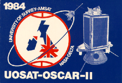
Oscar 11 is a UK-built amateur satellite launched in 1984.   It has been dead (well, almost dead) for many years.   But when the sun shines on the solar panels, it wakes up and transmits.   I've been able to hear it and -- more usefully -- see it on my RTL-SDR  HD-SDR receive system.  My antenna is my re-born (from the Dominican Republic) three element homebrew 2 meter cubical quad (see pictures below). 

I'm sorry the video is a bit out of focus, but you can clearly see the trace of the signal from the satellite. Realize that my HD-SDR software is about 10 kHz off calibration.  You can see the Doppler shift, and you can see the signal fading in and out as the old satellite tumbles through space.  Any ideas on what the other signals seen off to the side are?  Is anyone else listening for Oscar 11?  

https://amsat-uk.org/satellites/telemetry/uosat-2-oscar-11/

https://en.wikipedia.org/wiki/UoSAT-2

http://www.dk3wn.info/p/?cat=47


UOSAT_OSCAR-11


Monday, November 12, 2018

Getting Ready for Farhan's Satellite (videos)


I've been getting ready for the November 24 launch of the CubeSat that Farhan and his friends in India built.  I started out with my trusty Drake 2-B and a Hamtronics 2-to-10 downconverter, but I quickly switched to an RTL-SDR dongle and HD-SDR software.   My 3 element quad antenna is visible in the first video.   So far, I am using the Armstrong method to turn the antenna. 

In that first video I keep saying that I am waiting for AO-71.   In fact is was AO-73, the "FunCube" from the UK.   I think it is similar in power and antenna configuration to Farhan's satellite, so I think we are almost ready for launch.

(Any ideas on what that mysterious pulsating sig in the satellite passband signal is in the first video?)     

Monday, October 22, 2018

Ian Keyser G3ROO on UK TV with his Spy Set Rigs (video)

Me at the keyof one of Ian's spy sets -- ten years ago?
Check out this nice UK TV report on Ian G3ROO and his spy set radios: 

https://www.itv.com/news/meridian/2018-10-19/daring-spies-who-broadcast-from-behind-enemy-lines/

And here is Tony Fishpool's report on their excellent adventure at Friedricshaffen Hamfest 2018. 

http://www.fishpool.org.uk/friedrichshafen.htm

Here are some of the SolderSmoke blog posts on the activities of Ian and the Dover Constructors Club. 

https://soldersmoke.blogspot.com/search?q=G3ROO

Wednesday, October 17, 2018

M0HYT's Through-Hole (No Surface Mount) uBITX


That's the spirit! I like how Peter M0HYT took the uBITX schematic and built his own, his way.  When you build the rig yourself, if problems arise (spurs, harmonics getting past filters) you are in a much better position to fix the problem. I'm afraid that sometimes those buying an already-assembled board just feel aggrieved if the purchased item is not fully within specs.     

M0HYT posted this to the BITX20 group (this past summer): 

I have just built a uBITX with standard components (no SMD's) from scratch on a PCB I designed - it works well.  I have now designed another PCB which incorporates the Arduino NANO and the the Si5351 shield and I'm just waiting for the PCB's to arrive and then I will start assembling.  I made some changes to the circuit to allow for a dynamic microphone and the use of screened TOKO cols for the 30MHz lowpass filter, I also changed the coupling arrangement to the 45MHz filter.

I have attached a picture of the original PCB and a PDF of the new layout incorporating the Arduino and Si5351

Maybe one day I will play with SMT but for now standard components are still easily available !
 
73's - Peter M0HYT


Wednesday, September 26, 2018

The Triple Scratch-Built BITX Club -- Do you qualify for membership?


OK, so how many of you guys can join Steve M0KOV and me in the Triple Scratch-Built BITX Club?  

Bill 

Below are my three Bitx builds.

1st build.  
Closely follows Farhan's original 20m design but I soon changed the VFO for an arduino/ad9850.  It was a fast, get me on the air build, it worked, but not well.
The output amp was built on a separate board as part of its exorcism. 

2nd build. 
This was to be my two band Hill Topper, we don't have mountains in Yorkshire. Built with separate stages slotting into the eddystone box to save space and to help with shielding. The receiver worked very nicely, the output kept blowing irf510's. I later found that they were a hopeless batch. Very hard to work on.


3rd build. Big is beautiful. Arduino/si5351 straight into the modulator and into the mini-circuit mixer through a driver as discussed. Norton feedback RF preamp and a ne5532/lm386 AF amp. At the moment it's on 80m but it did start on 40m. It's still a work in progress and I will have to sort that soldering iron band change.

73  Steve M0KOV

Tuesday, July 3, 2018

The Moxon Files from L.B. Cebik W4RNL


I had thought that the Cebik files were lost to us in some sort of legal copyright struggle.  But in my effort to better understand the Moxon antenna, I found a real treasure trove of Cebik's writing.  These should all be saved somewhere safe. 

I especially liked his description of the evolution of the Moxon antenna.  Les Moxon was apparently very unAmerican in his emphasis on reception (not transmit gain)  as the main benefit of the beam antenna.  He also sought to avoid superfluous luxuries like rotators, but Cebik hints that rotators have become an important part of our American way of life.   Indeed.   
Before I found these files I had been on the verge of giving up on efforts to replace my storm-damaged Moxon.  After all, solar minimum is still ahead of us.   But after reading OM Cebik's articles I have decided to build a 20 meter version and place it above the center point of a 130 foot doublet.  I will have the best of both worlds.  

http://www.antentop.org/w4rnl.001/mu0.html

http://www.antentop.org/w4rnl.001/mu2a.html

L. A. Moxon, in his HF Antennas for All Locations, provides the essential clue: "the main benefit [of a beam] accrues from the reduction of interference during reception, though the 4 to 6 dB gain provided by typical amateur beams is an important bonus and probably the reason which carries the most weight with the majority of amateurs."(2)Here is a theory of beam operation quite unAmerican is style: instead of gain, Moxon strives for front-to-back ratio as the most crucial aid to ham operation. His statement is an affirmation of the "good ears" theory of operation. Even more, it forms the basis for his rectangular improvement upon the VK2ABQ square.
...
 Moxon prefers matched elements, tuning each of them to optimum performance remotely. That way, he can reverse the beam and do away with expensive and maintenance-intensive rotators. However, rotators are a way of life in the U.S. (a TV rotator will likely handle a 3-band Moxon beam), and there are many uses for portable beams that are hand-rotated or fixed in the field. Thus, I decided to continue the exercise in unequal element lengths.

http://www.antentop.org/w4rnl.001/mox20.html

Finally, a treasure trove of Cebik's writing: 

http://www.antentop.org/w4rnl.001/radio.html


Thursday, June 21, 2018

"Hot Iron" #100 -- Thanks Tim Walford!


Tim Walford, G3PCJ has put out issue #100 of Hot Iron, the Journal of the Constructors Club.  That my friends is a long time publishing a quarterly.  25 years!   And it is a wonderful publication, filled with ideas and inspiration.  

Tim tells us in #100 that he is passing the baton (the Hot Iron?) to Peter Thornton, G6NGR who will keep the iron hot from here on out.   Peter is looking for contributions for issue #101.  Please try to help him out.  

Thanks again to Tim.  Good luck with the farm and the house moves.  


Wednesday, February 7, 2018

Understanding Switching Mixers (as in the Ceramic DC RX)

W3JDR's Comment on my post about the DC RX mixer got me thinking.   He was right -- my explanation of the mixer action wasn't quite complete, especially as far as switching mixers are concerned.  I remembered that I had written about this in the SolderSmoke book.  Below you can see the part of the book in which I discuss switching mixers.  Realize that the two diodes in F5LVG's mixer play the same role as the two gates in Leon's circuit.  It will be worth your while to sit down with Leon's circuit diagram, his frequency chart,  and a ruler and really go through this so you can SEE and really understand how the two gates (or switching diodes) generate sum and difference frequencies.  

-----------------------

I guess I still yearned for clarity and intuitive understanding...  Time and time again, as I dug into old textbooks and ARRL Handbooks and promising web sites served up by Google, I was disappointed. 
Then I found it.
It was in the Summer 1999 issue of SPRAT, the quarterly journal of the G-QRP Club.  Leon Williams, VK2DOB, of Australia had written an article entitled “CMOS Mixer Experiments.”  In it he wrote, “Generally, mixer theory is explained with the use of complicated maths, but with switching type mixers it can be very intuitive to study them with simple waveform diagrams.” 
Eureka!  Finally I had found someone else who was dissatisfied with trigonometry, someone else who yearned for the clarity of diagrams.  Leon’s article had waveform diagrams that showed, clearly, BOTH sum and difference output frequencies.


Switching mixers apply the same principles used in other kinds of mixers. As the name implies, they switch the mixing device on and off.  This is non-linearity in the extreme.
Not all mixers operate this way.  In non-switching mixers the device is not switched on and off, instead one of the signals varies the amount of gain or attenuation that the other signal will face. And (as we will see) it does this in a non-linear way.  But the basic principles are the same in both switching and non-switching mixers, and as Leon points out, the switching circuits provide an opportunity for an intuitive understanding of how mixers work. 

Let’s take a look at Leon’s circuit.  On the left we have a signal coming in from the antenna.  It goes through a transformer and is then applied to two gate devices.  Pins 5 and 13 of these gates determine whether the signals at pins 4 and 1 will be passed on to pins 3 and 2 respectively. Whenever there is a positive signal on gate 5 or on gate 13, signals on those gaps can pass through the device.  If there is no positive signal on these gates, no signals pass.  Don’t worry about pins 6-12.


RF A is the signal going to pin 4, RF B is the “flip side” of the same signal going to pin 1.  VFO A is a square wave Variable Frequency Oscillator signal at Pin 5. It is going from zero to some positive voltage.  VFO B is the flip side.  It too goes from zero to some positive voltage. 
Look at the schematic.  Imagine pins 5 and 13 descending to bridge the gaps whenever they are given a positive voltage.  That square wave signal from the VFO is going to chop up that signal coming in from the antenna.  It is the result of this chopping that gives us the sum and difference frequencies.  Take a ruler, place it vertically across the waveforms, and follow the progress of the VFO and RF signals as they mix in the gates.  You will see that whenever pin 5 is positive, the RF signal that is on pin 4 at that moment will be passed to the output.  The same process takes place on the lower gate.  The results show up on the bottom “AUDIO OUTPUT” curve. 
Now, count up the number of cycles in the RF, and the number of cycles in the VFO.  Take a look at the output. You will find that that long lazy curve traces the overall rise and fall of the output signal.  You will notice that its frequency equals RF frequency minus VFO frequency.  Count up the number of peaks in the choppy wave form contained within that lazy curve.  You will find that that equals RF frequency plus VFO frequency. 

Thanks Leon!  

Monday, October 2, 2017

TRGHS: I Can Hear the Roosters of Boa Vista


At the instigation of  Bob N7SUR I've been working on a simple, easy-to-reproduce Direct Conversion receiver for 40 meters. I'm building this for my nephew John Henry,  and I'm hoping this will be a circuit that others can use to break into the ELITE corp of successful ham receiver builders. Coincidentally Joh in Freiburg Germany is working on a very similar project -- we have been comparing notes. 

At first I used an FET detector described by Miguel PY2OHH.  It worked, but at night the AM detection of powerful shortwave broadcast stations drowned out the amateur signals.  So Joh and I started to explore detectors that would eliminate this problem.  I went with a version of one described in SPRAT by F5LVG ( "The RX-20 Receiver"- see below).  Very simple:  A transformer to two back-to-back diodes with a 1K pot to balance the signal from the VFO.  OM Olivier used a very, very cool transformer: he took two small, molded chokes and simply glued them together!  22uH choke as the primary, 100uH choke as the secondary. I went with one of the toroidal transformers that Farhan left me when he visited in May. 

 I'm using a varactor-controlled ceramic resonator VXO  (no Si5351 in this one!) and a non-IC AF amp designed for use with ear buds (the world is awash in ear buds).  It is a "singly balanced" design with the incoming RF signal being the one "balanced out" in the detector.  

Last night the receiver passed the AM breakthrough test.  The SW broadcast monsters were balanced out and kept at bay. 

This morning the receiver passed The Boa Vista Rooster Detection Test.   I fired up the receiver and heard an operator speaking Spanish with a Brazilian accent.   When I heard the rooster crowing in the background I knew it was Helio PV8AL from Boa Vista Brazil.  TRGHS -- this little receiver is a winner.  

I'll try to post a schematic soon.  

And hey -- look at what wonderful IBEW (International Brotherhood of Electronic Wizards) project this is:   Instigation and inspiration from Oregon.  Some design ideas from Brazil.  A French detector circuit described in a British QRP magazine. A transformer from India.   A collaborator in Germany.    And finally, the rooster of Boa Vista.    


Let's not forget Wes Hayward W7ZOI for bringing back (in 1968!) the neglected Direct Conversion idea.
Designer: Douglas Bowman | Dimodifikasi oleh Abdul Munir Original Posting Rounders 3 Column