Just go to http://soldersmoke.com. On that archive page, just click on the blue hyperlinks and your audio player should play that episode.
http://soldersmoke.com
The Radio Gods were clearly supporting me on 16 October 2019. I had sent out a plea for people to listen for the 80 mW CQ from my ET-2 rig. I had specified 0930 Eastern as the time. Little did I know that there would be a contest at that hour (on a Wednesday morning!) on 40 meter CW. There was no chance of my signals getting through. I leaned that the contest would be over at 1000 hours, so I waited and called CQ again at that hour. Jim W1PID had guessed that I would do that. I immediately recognized his call -- he was often at the other end of Michael Rainey's most daring low-power adventures. He was a participant in the famous Rexpeditions, including a coastal effort to send Michael's voice-powered CW signal across the Atlantic. His normal operating habitat is in the field. We had a wonderful QSO. He told me I peaked at S-6.
I have worked W1PID on at least two Straight Key Nights and this blog has had many postings about his long-standing involvement in QRP.
So yesterday I made my first contact using my ET-2 rig. Last night I got an e-mail from Gary, the fellow at the other end of that contact:
Evening
Bill, N2CQR….Yes I did learn about you from the spot on the DX Summit
cluster. I tuned to the freq to see if I could even hear your 80 mW and
you were a good real 569 when calling CQ. You built up to a real 589 on
the later transmissions. I did not have either of the two pre-amp
positions on in the ICOM 756 Pro II. There was not any QRM on the freq
either. Your spot indicating the 80 mW is what really got my attention.
My antenna is a 2 element yagi at about 115 ft and it really works great for me.
Thanks
for the picture of the great little transmitter. Glad to be your first
DX QSO with it. Hi Hi Maybe again soon. My pleasure to work you.
73, Gary, K4MQG
Fort Mill, SC
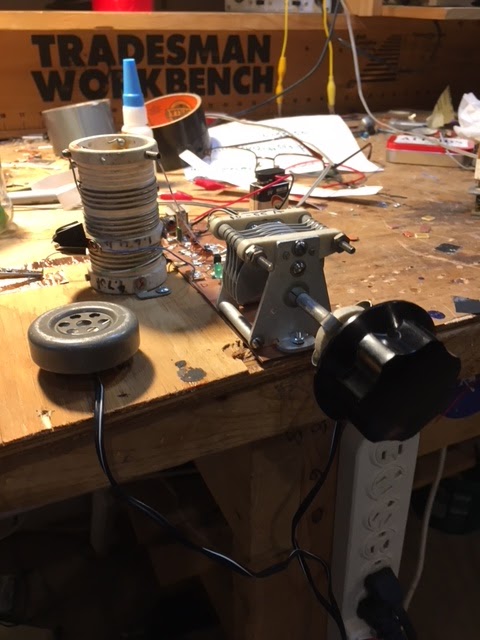
Farhan commented on yesterday's post, saying that it was hard to tell (from my pictures) where he rig started and ended. He was right. So this morning I have tried to clean up my bench a bit -- I hope these pictures are better.
Above you see the whole rig. The transmitter board is right next to the key that Farhan gave me. You can see the 7040 crystal. A C-Clamp holds to the bench the piece of scrap plywood that serves as the base for this rig. Next to the C-Clamp you see the TR switch -- the just switches the antenna -- both transmitter and receiver are powered at all times. I can hear the transmit signal in the headphones and this serves as my sidetone.
Here is a close-up of the transmitter with the schematic below:
The transmitter is VERY simple. Nine parts, including the low-pass filter. You can barely see the J310 FET to the right of the crystal.
Here is the receiver:
I really like N0WVA's regen. The green diode in the source circuit is the key. This one does not squeal when you go into excessive regeneration (when you think about it, regens should NOT squeal at audio frequencies -- but most do). Also, the green diode dims a bit when you are at the right amount of regeneration. In the picture you can look down the tube of the variometer that Pericles HI8P gave me many years ago. The big variable cap is from the junk box -- I think it may be from a Johnson Viking transmitter. Note the long shaft with the insulating connector -- this is to reduce the hand capacity effect. On the right you see a smaller cap with just one vane -- this is my fine tuning control --- with the smaller cap at mid range, I would just set the big capacitor to put the receiver at 7040 -- with the smaller cap I could tune +/- 12 kc. I also used an insulating shaft on the smaller cap -- the connector for this one is from an old 1930s era regen that I picked up at the Kempton Part rally in London.
Instead of the audio transformer and Radio Shack headphones, I just used some old DLR-1 WWII Headphones. They are very sensitive and work well.
Lots of soul in this new machine: The variometer from Pericles. The WWII headphones. The 1930s era shaft connector. The circuit idea from the Autumn 2001 SPRAT. Farhan's key.
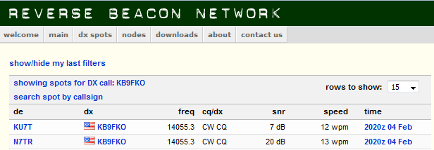
I recently read on Hack-a-Day of a new FPGA chip that has on it 35 BILLION transistors. I'm sure that thing can produce some fascinating results, but can anyone really understand it, or feel that they really BUILT something that has that kind of chip at its center? On the other hand, I did rely on a lot of modern digi technology in this project: The Reverse Beacon Network reported back that my unanswered CQs were in fact getting out (one as far as Kansas to K9PA). And in the end I had to ask -- via the DX Summit Spotting cluster -- for someone to listen for me. So I can't go full Luddite here. And I wouldn't want to have to use a rig this simple every day. No way. It is just too hard to use. But there is a beauty and a challenge in simplicity. There is some virtue in using just two transistors instead of 35 billion.
Thanks to N0WVA, W2UW, VU2ESE, HI8P, K4MQG, The G-QRP club and their inspirational journal SPRAT, the RBN and the DX Summit.
In my effort to replicate the ET-1 rig of Glen Yingling W2UW, I had a hard time getting the receiver to work well with the single FET being switched between receiver and transmitter, so I retreated a bit and went with individual FETs for the TX and the RX. This doubled the transistor count -- to TWO. So it is an ET-2.
I also boosted the power to 80 milliwatts by putting 12 V on the transmitter. The receiver was running off the 9V battery you can see in the left in the picture.
Here is the story of the contact:
To K4MQG from N2CQR:
Gary:
Wow thanks for the QSO today. I was using 80 mW transmitter that
consists of just 8 parts! The receiver was a regen using one single
transistor. So one transistor on transmit and one transistor on
receive. And it reached South Carolina.
I
was about to give up hope. I had been calling CQ for days. Then I was
talking to Rob VE4GV on 20SSB. Rob suggested that I "spot myself" on
one of the DX clusters. So I did (see below). Obviously you saw my spot and a
minute or so later, SUCCESS! I'm really pleased.
Attached
is a picture of the rig. The transmitter is around the crystal and the
blue pot on the right. The headphones are from WWII. The receiver was
powered by the 9V battery. The regen uses a variometer given to me by a
friend in the Dominican Republic in 1992. The main tuning dial is
connected to the cap by an adapter from a 1930s-era regen. Antenna was a
40 meter dipole at about 25 feet. Obviously your 3 elements a 115 feet
were doing the heavy lifting.
Thanks again Gary!
And thanks to Rob for the suggestion on the spotting.
I got my version of the ET-1 transceiver working. As I described in previous posts, I first got the transmitter and the receiver working separately, each with their own J310 FET (oh the extravagence!)Then I built a switching arrangement that allowed for just one shared FET and very short leads. I used a 4PDT "push button" switch from an old Ramsey Electronic LC meter. See the last picture for details. I use the tube from a pen to operate the switch (that's the green thing in the picture).
It is inhaling and exhaling. My 20 mW signal is being picked up on the Reverse Beacon Network, mostly in New England, but today in North Carolina.
No contacts yet. I may have to resort to scheduled contacts. OM Yingling W2UW was operating during much better propagation conditions (2001), so I don't think I will ever get close to his impressive (23 states!) operating record.
But it has been fun getting this thing going. The N0WVA regen design is one of the best and simplest regens I've ever built. It is really nice --hardly demonic at all.
I can run the whole thing off one 9V battery. I think it is a cool looking machine.
My son Billy was back from college over the weekend (he came back to help me celebrate the completion of yet another orbit of the sun). I was showing him my 8 part rig and telling him that it puts out 20 mW. He asked a good question (he is a scientist): What is the voltage at the antenna terminal. I checked: ONE VOLT rms. About 1.414 volts peak. Think about that. My transmitter is sending a signal to New Hampshire from Virginia on less than the voltage of AA battery. Two more spots on the Reverse Beacon Network (see above). Another skimmer station in New Hampshire. My signals seem to like the granite state.
50th PODCAST WITH OUR FRIEND PETE! THREE CHEERS FOR PETE!
Pete's Bench Report
-- Transceiver Count: FORTY! -- SDR RADIGS -- Colorful OLED screens -- Pilgrims and Paisanos -- "Left Coast Homebrew SSB" -- Pete builds a CW transceiver (see picture above)
Bill's Bench Report:
-- Going minimalist -- Tuna Tin 2 + Herring Aid 5 = Fish Soup 7 (and later 10) -- My QRPp QSO with K1PUB overheard in Canada -- Glen Yingling's ET-1 -- Bill attempting a single transistor transceiver
SPACE NEWS
-- Antuino's Cubesat Origins. Farhan's Antuino Mods -- Apollo 11 Anniversary -- Possibly the best space book ever: "Carrying the Fire" by Michael Collins -- Chinese microsat sending eclipse pictures from the moon -- LightSail 2 success -- India has spacecraft in lunar orbit.
Eric Sears ZL2BMI and Dino Papas KL0S on "QSO Today" Podcast
MAILBAG: ZL2PD's Sugar Cube VFO N8WQ gets free samples N5RWF Getting started, wisely wearing beret VK2EMU Australian Ad for Collins Filters W1PJE on new LDMOS PA transistors KA4KXX Al Fresco 75 meter SSB rig with model plane engine mufflers!
Forgot to mention: W9TH still has manuals for whover owns Drake 2-B #4215. Check your serial number!
In my previous blog post I'd expressed skepticism about using a single transistor regen on the air. But over the years I've learned to give new receivers a chance. They usually don't work perfectly on the first try. You have to work with them. It is almost as if you have to peak and tweak a lot in order to get them to properly inhale signals from the ether. That has been the case with this little receiver. I found some silly mistakes in my construction. And I decided to try some more sensitive headphones. I ditched the 1000 to 8 ohm AF transformer. And I added a very small variable cap for fine tuning. The results are amazing. See video above. It performs as well as most of the direct conversion receivers I've built. It is remarkably stable. I do think I could make contacts with this receiver. I might eventually go the full ET-1 route and try to do it with a single switched FET, but I think my next step will be to built a single transistor crystal controlled transmitter on the same piece of wood, and try to makesome contacts with a two-transistor rig.
My success with the Fish Soup 10 QRPp transceiver got me interested in further minimalization. About ten years ago I built a rig presented in SPRAT 108 as the ET-1 by Glen Yingling W2UW. It re-appeared in modified form as the FETer by G3XBM in SPRAT 137. This rig uses just ONE active device, an MPF-102 FET that is switched via a 3 pole double throw switch from transmit to receive. The transistor is switched. The receiver is a regen and the transmitter is a very simple crystal controlled one stage oscillator. See: https://soldersmoke.blogspot.com/search?q=ET-1 for info on my ET-1 effort. The transmitter was the easy part. I don't think I made any contacts with this thing. That has been kind of bugging me. So I tried it again. Again, I had trouble with the receiver. So I looked around for another single FET regen receiver design. I found one on AA7EE's page. It was designed by N0WVA: https://aa7ee.wordpress.com/2015/02/07/n0wvas-one-fet-regen-optimized-for-ssbcw-sounds-great/
I've had a variometer in my junk box since about 1994. (Given to me by Pericles HI8P. QEPD.) It was time to use it as the coil and ticker for this rig. I liked the green LED in the source, and the promise that this thing would not oscillate at audio frequencies.
I built in on one morning. See pictures. It works. I can hear CW stations. But I think I would have a tough time making contacts with this thing. OM Yingling worked 24 states with his ET-1. Respect.
Note the cool BLUE numerals. They represent 7040, 7050, 7060, 7070. The little black "pointer" is from a power cord wall fastener. My tuning cap has a nice reduction drive -- the pointer follows the movement of the capacitor blades. The VFO is very stable. Simplicity is a virtue. CW is, I think, outmoded and kind of absurd (one letter at a time? really?), but it does allow for extreme simplicity. Using a rig with just 10 transistors, putting out half a watt of RF, I am regularly communicating with people. This is what I like about CW. I've had about 12 solid contacts with this rig since putting it on the air earlier this month. The VFO was a huge improvement over being crystal controlled. Crystal control was OK back when receivers were broad and hams tuned around for replies, but those days are gone. Getting the transmit offset set correctly was another huge improvement.
The box with the two grey knobs on the left is the Herring Aid 5, the receiver that took me 38 years to complete. The box on the right is a VFO I originally built for my first BITX40Module -- it started out around 4 Mhz but I pulled turns off the coil until it was in the 40M CW band. The Altoids in near center has the buffers -- a 40673 MOSFET and a 2n3904 BJT. The box in the back holds the Tuna Tin 2. There the oscillator has been reconfigured as an amp. A relay switches the output from the buffers between the receiver and the transmitter. That big switch in the center switches the antenna and the 12 V for T/R. The circular black thing is piezo buzzer used for CW sidetone -- I have it glued to the board upside down to keep the volume down.
The whole thing is mounted on a kitchen cutting board. A breadboard!
The most difficult part of all this was getting the needed 800 Hz drop in TX freq on transmit. You need to do this with a rig like this or else you won't be in the other fellow's passband. I did a lot of cut and try -- in the end I put a 5 pf cap across the coupling cap from VFO to buffer. This 5 pf cap switches in on transmit via a small relay. It works. I just spoke to N8AFT out in Columbus, Ohio and I was in his passband.
So five transistors in the receiver, two in the transmitter and three in the VFO/Buffer. So it is the Fish Soup 10.
It puts out about half a watt. On CW. I am feeling virtuous and vaguely superior. I've made several more contacts. It all works very well and is a lot of fun.
We've continued on with this project and it has been a lot of fun.
Sure, there's
THE JOY OF OSCILLATION
but we've progressed to
THE JOY OF MODULATION (added a keyed buffer)
THE JOY OF AMPLIFICATION (added driver and PA, not threatening QRO, yet)
THE JOY OF RADIATION (perhaps my favorite) THE JOY OF RECEPTION (picked up by RBN, yeah!) last on the list is to experience THE JOY OF COMMUNICATION
for that, we'll try out a number of different receivers. Cheap SW portable. Softrock Lite. websdr.org.
Does one try to count all the joys? :-)
Here's a few snaps:
0.jpg - RBN evidence 1.jpg - lashup on the lid of a tupperware container This worked great for throwing the work in progress in a backback for our build session meetups. 2.jpg - Fig 1.34 less output LPF. 3.jpg - The missing LPF. THE JOY OF FILTRATION (OK, that's taking it too far.)
4.jpg - Fig 1.35 amp with BD139 transistor. 5.jpg - "breadboard" and a front panel to hold the T/R switch. Key and cheap SW portable for RX. Waiting for DX contest to end, so I have a chance. :-) 6.jpg - simple breadboard chassis
Our fun has certainly been cheap. The parts cost, including PCB and 1 BNC jack, was about $13 in low quantity from Mouser (and Diz) for all but the amp. The amp portion was $4 in low quantity from Mouser (and Diz), and most of that was the expensive heatsink. The "chassis" was just a piece of cheap 3/4" hardwood and lexan from home depot. I drilled and tapped the holes in the wood for the #4 screws. (Seems to hold quite nicely. I thought I might have to harden the threads with CA adhesive as is done sometimes with balsa.)
If there are any of those air variable caps left that you are meting out to the worthy, well, like Wayne and Garth, "we are not worthy." If you do have between 1 and 4 and find it in your heart, we'd be very grateful.
Dear Friends, The UJT transmitter circuit was improved considerably today. The power output has increased to 1.48mW and the start-up "whoosh" is now far less objectionable. It's currently running in beacon-mode at 3687.8kHz. I'll resume "CQing" as soon as I've returned from an hour's walk in the woods. I hoping to work K1QO among others. 73, Mike Added five QSOs today. Seabury/AA1MY is in Maine...exactly 100 miles from my doorstep. It's wild to think that we made a one-hundred mile radio contact on a unijunction.
AA1TJ writes: I spent most of a week working to raise the RF output power from my unijunction transmitter to nearly 1mW. I was rewarded this evening with two contacts.
Jim/W1PID exchanged (599/449) signal reports with me from Sanbornton, NH (112km) at 2210z!
Dave/K1SWL did the same (589/229) from Newport, NH (95km) some four minutes later!
I should think these were the first-ever radio contacts made using a unijunction transistor as the transmitter.
FYI: my receiver was comprised of a single 1N34a germanium diode mixer followed by a single 2N35 germanium transistor audio amplifier. Great signals on this end.
Michael updates Peter (and us!) us on his efforts of this week:
Grüss Peter!
Thanks for the nice message. Yes, I knew that you were going to be QRV with your ZnO transceiver but I never heard if you had made any contacts. I guessed that you had not, otherwise I'm sure you would have let me know.
Again, I think your circuit looks really great! It's amazing to think you managed to squeeze 500uW from a scrap of oxidized zinc-plated steel. Even if you didn't make a contact, what you are doing is really fantastic. Congratulations on the creation of this amazing radio!
Okay, so I spent most of the afternoon at the workbench. Thus far I'm only using a single SRD (step-recovery-diode...1N5401 rectifier). Of course the result is a unipolar pulse. The idea did work as planned, however the power only increased by 2.24dB. The maximum RF output power is now 230uW. At least the SRD makes a pretty pulse :-)
Please find two scope captures attached to this message. The first (0002) shows the SRD generated unipolar pulse. As you can see, the pulse width is nearly perfect for the job. The second trace shows the output RF waveform. The worst spurious energy is ~20dBc. The second image shows the 507kHz waveform at the unijunction emitter along with the output RF waveform.
The beacon is presently off the air, but I look forward to trying my luck tomorrow with a back-to-back pair of SRDs. A bipolar pulse pair will provide a shock impulse once every 3.5 cycles, instead of once every 7 cycles with the present unipolar drive pulse. The bipolar pulse pair should result in increased RF output power as well as a slight spectral improvement.
It's only a matter of time before you make a ZnO QSO, Peter. As we always say, the difficulty merely sweetens the eventual success.
A broadband measurement of my output power (using an AD8307 log-amp power meter) indicates 139uW. Spurious frequency energy accounts for 2uW, leaving 137uW at 3.552MHz. I believe this is roughly the output power produced by your ZnO transmitter?
This morning I'll attempt to increase the unijunction (UJT) 80m RF output power by inserting a pair of back-to-back standard-recovery power supply rectifiers (1N5401-ish) at the UJT base-2 to ground node. Thus far I have relied exclusively on internal UJT nonlinearity for the generation of harmonic energy. I've reason to believe the minority carrier charge-storage capability (normally a defect, but hopefully a virtue here!) of these rectifiers will efficiently produce a bipolar pulse-pair every 1/500kHz seconds resulting in an odd-order comb-spectrum. At least that's the plan...we'll see how it works out ;-)
Peter, I never heard the results of your ZnO DXpedition? Any luck OM?
Okay, I'm off to the Hobbit-Hole. My heartfelt thanks to you all for your shared interest in this cock-eyed project.
73,
Mike, AA1TJ
Peter, DL3PB, in Germany respond with amazing news of his own. Peter is homebrewing his own tunnel diodes, using Zinc Negative Resistance Oscillators. No store-bought appliances for him!
At this point you really have to visit the pages of Nyle K7NS
Nyle tells of building a little microwatt transmitter, and, once the snow melted, climbing a hill 5 miles from town to see if he could hear it. This reminded me of young Marconi's early efforts in Bologna.
Peter writes:
Hi Folks,
Mike, your plan on how to increase output-power sounds reasonable – yes, a few dB could really help, to make reception a bit steadier and thus allow a QSO.
Well, I thought we had already talked about the ZnO TRX attempt, but obviously we didn’t. The reason is dead simple - It didn’t work.
[ The ZnO TRX is a minimalist 80m band transceiver with a homemade tunnel-detector-diode as the only active device – based on Nyle’s K7NS experimentshttp://sparkbangbuzz.com/zinc-osc-2/zinc-osc3.htm – please find attached an early schematic ]
Three days in a row after Xmas I tried for several hours each, I had announced the activity on QRPSPOTS and the German QRP Forum. Thus several guys within the right distance were really trying hard to copy. I used different temporary antennas, mostly verticals, but also a sloper dipole - nada, niente , nothing. One or two OMs reported weak CW signals on the scheduled QRG, but too deep in the noise, to even make out, whether it was me or someone else.
Yes, power is more or less comparable, actually it’s 0.5mW +/-3dB depending on the day’s form of the homemade tunnel-detector, but I guess all my antennas are some dB behind a full-size dipole, so at the end it’s pretty much the same.
Folks were very cooperative during the test itself, but after it was clear, that it had not worked, the usual trolls showed up to explain, why that never could have worked... I plan another test within the coming week e.g. during the PA-contest next weekend ( I’m only 30km from the dutch border ) with a base loaded 15m vertical – be assured, you’re the first to hear about any success in terms of QSO or just being heard anywhere.
What would we go for, if everything works as expected and/or right from the beginning – or as Jim said it : What fun...
73!
Peter/DL3PB
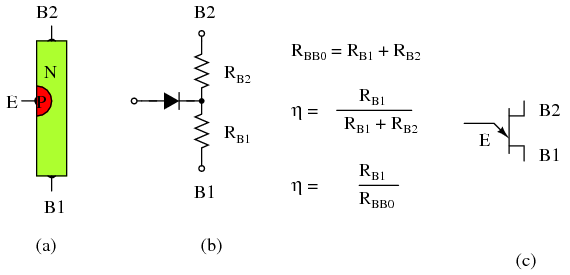
Finally, Alan Wolke provides a very illuminating (as always) explanation of tunnel diodes):
Miguel PY2OHH is the Wizard of Sao Paulo. This morning I was looking at his wonderful web site and came across this little rig. It seems a bit simpler than our beloved Michigan Mighty Mite. And the folks down in Brazil had several of these on the air and made contacts with them. FB. Miguel hints they may turn this rig into a transceiver.
Bill N0YUD built this really nice Michigan Mighty Mite. I like the wood base (with little feet!). And the classic black 35 mm film container. And the Vero board. Fancy connectors too! Nicely done Bill.
Bill has also wisely left space for a low pass filter. As you can see in his 'scope picture below, the MMM produces a lot of harmonics. With a low pass filter, that mess will turn into a beautiful sine wave. We'll be talking about harmonics and low pass filters in the next podcast.
Feb 20 at 3:31 PM
Hi Bill and Pete,
I just completed my Michigan Mighty Mite and am proud to announce it seems to be generating about 1 watt of what appears to be extremely harmonically challenged RF. I was worried about the ugly signal on my scope until I saw another screen shot on the blog page that looked almost exactly the same as mine.
What a fun project and lots to learn with just 7, or in my case 8, parts (I had to stack a couple of 56ohm resistors). I utilized those small pc board sockets for the coil and crystal so I can easily change bands and also left room for a low pass filter....
I am still struggling with the tank coil theory and impedance... Impedance matching is a very murky area for me!
I am looking forward to building the low pass filter. By the way, I checked for third and fifth harmonics and could not hear anything on my receiver. There's another question, why does this circuit generate odd harmonics? Fun stuff, this learning game!
I love the Podcast! Thank you for your efforts and keep them coming.
Bill and Pete, I bring news of the California Mighty Mite as Bill dubbed it.
I repeated the steps as documented in version two with Pete's parts. I had one hiccup. I was winding L1 with Pete's red wire when, on turn 42, I ran out. Luckily a search of the workroom revealed the last two coils of radio shack magnet wire that I bought with the Gold wire. I checked the thickness of the Green-coated wire and found it to be one gauge smaller than Pete's wire. To be ready in time for the podcast, the green wire would have to do. It was fussier that the larger gauge wires, but with my trusty electrical tape, the L1 coil stayed on the coil-form quite neatly. Using a scrap of gold wire, I wound L2 making sure to tape it evenly spaced.
Next I remeasured each of the parts to be soldered and arranged them in according to the Schematic. With the Soldering iron hot from warming while I would the coil, I detached the 365pf varicap from the MMv2. I strapped on the heatsink to the 2N3058 transistor and soldered the 27Ohm resistor to the Emitter. I attached one pole of the Colorburst crystal to the solder tab on the varicap along with the stripped end of L1 coil. I soldered the Collector to the Tap-2 of the L1 coil, then the Base to the other pole of the crystal. I then attached the 10k resistor to the base and attached another red-magnet wire to the side of the varicap. Almost done I looped a 47nF ceramic capacitor to the 2 power posts of a DC connector, then wrapped the Tap-1, 10k, and the lead from the varicap into the pin (positive) solder tab of the DC connector. I took a second red scrap and stripped the ends, stuck it in the sleeve (negative) solder tab.
Two applications of solder later, the multimeter was back out for a final continuity check. After checking across every joint, I plugged in my power supply to the Mighty Mite. Reaching over to the shortwave I leaned in the power button and tapped in the Colorburst frequency, 3-5-7-9. Static filled the room as I made sure the radio was how I left it earlier that week. SSB mode, attenuator off, and volume up. My finger tingled as caressed the straight key, now wired to the resistor and negative line. I was scared something would melt or flame up when I keyed down. Well no way to find out, except to do.
The key spring resisted, but I felt metal below as the key bottomed out. The radio let out a sound like rubber going down a slide and faded as I held down the key.
Gentlemen, we have Oscillation.
Revision 3 was a success. Version 1 being breadboard and Version 2 being Bill's crystal and what I had on hand.
I tried tapping out CQ, but was faced with the chirping fact that I haven't practiced in a year. I don't even know TEST let alone CQ CQ KK6JTL TEST. I turned the varicap to see if the sick squeal got any better with adjustment. It did and the pitch out of the radio changed after a bit. I must be changing frequencies! I spun around and fired up the computer. The RTL-SDR would show me what I was doing and who may respond, along with who I might be interfering with.
With the waterfall display zoomed in, showing about 5kHz around 3579kHz, I went back to the Mighty Mite. I saw one CW QSO going on in 3575kHz and two other spikes at 3576-3578kHz. Any guess at what those are? I knew since Sunday night I had been listening to JT65-HF. I reached over and held the key down. A big red spike went up at 3576.5kHz
I waited for quiet and keyed down. I turned the varicap to lower the capacitance. The spike moved to a higher frequency. When the varicap was half out, the squeal began to sound like a tone again. Problem was I was still at 3578kHz and still stepping on the JT65 signals. I called my wife in in excitement to show her and asked her to help me tune the circuit to the official frequency. I'm going to leave the varicap there for now. So I start it at 3577 and have to dial it back to 3579 to operate. I can almost go to 3580 with this little Mighty Mite.
Finally I was curious. I had forgotten to check the output of the transistor Pete sent me on my LC meter. So I got the datasheet from the Internet. The BC547A I had used in Versions 1 & 2 were rated for 325mW. The 2N3058 is rated for 5W. Pete, how much power does this put into an antenna when fed with 12V? Apparently not enough to wake my Radioshack SWR/Power meter. But that thing is hungry. It needs more than 2 Watts for it to function correctly.
Pictures attached. The transistor heatsink looks like it it touching the varicap in the pictures but I made sure there is plenty of gap. Too bad none of the pictures of that gap turned out. The wiggle in the waterfall picture is due to me turning the varicap to show range. Pete left a grounding wire on the case of the crystal. I chose not to remove it, but did not attach it to anything.
Congratulations Jacob! You really hung in there, overcoming obstacles including the US Postal Service's Crystal-Crushing Steam Roller. The rig looks great!
"SolderSmoke -- Global Adventures in Wireless Electronics" is now available as an e-book for Amazon's Kindle.
Here's the site:
http://www.amazon.com/dp/B004V9FIVW
May 2, 2024. The Choices We Make.
-
There is absolutely nothing exciting about today's blog other than to share
a bit of musing I did yesterday.
The occasion was sitting at the Board and C...
CEPT: Using a US callsign in Germany?
-
Many thanks to Spencer (WD4AWD) who writes: Hi Thomas, [I] know you’ve
operated abroad a number of times, in some cases with a country-specific
call (UK, f...
Conversion of NOELEC style balun board to 1:1
-
This article describes a small 1:1 balun for use in measuring field
strength using his TinySA Ultra and a small loop antenna. The balun is also
useful for ...
Frans puts his new KiwiSDR2 on the air and online
-
Many thanks to SWLing Post contributor, Frans Goddijn, who writes: Dear
Thomas, Last week I bought & installed the new KiwiSDR receiver and shared
it on th...
An Inline RF Step Attenuator for QRPp Work
-
I don’t need to explain the attraction of low power operation; if you’re
reading this, the chances are that you are already a convert. I’ve been
operating ...
A 51S-1 Restoration Story
-
I came across my Collins 51S-1 in a big junkyard in Ankara, Turkey around
2012. It was in a pile with a lot of other electronic scrap, probably from
one o...
New QRP Cluster Online From OM0ET and OM6APN
-
By DX EXPLORER
DX EXPLORER
Paul OM0ET and Peter OM6APN recently launched a new cluster dedicated to
QRP operations. Have a look and I hope you will enjoy...
3D Printing The Hadley 114mm Newtonian Telescope
-
Yes, we’re building a 3D Printed Newtonian Telescope called Hadley. It’s
being printed in PETG and in the video below, I give a quick tour. My build
isn’...
3D printed project boxes
-
I have been busy with some other things that have kept me away from
electronics projects for quite a while. Now I can get back to them, but
realize I n...
Daylight Again – An all Analog Radio
-
What’s all this? In 10 seconds, A high performance, 7MHz, 5 watt SSB rig
Draws just 24 mA of current 90 dB dynamic range, 80 dB close-in dynamic
range 3D ...
Adding Enclosure to your sBitx Boards Order
-
The early buyers of the sBitx board set who bought it for $270 USD might
want to also add the enclosure (box) for in the kit. What you will now get
is a f...
Digi-chirp! Digital synthesis of ‘nostalgic’ CW
-
The bottom ends of 80, 40 and 20m are not what they used to be. For
starters, the busiest part is the digital segment where computers talk to
computers – l...
-
A Simple Speech Processor
(For QRP/SSB Homebrew Transceivers )
Over the last few weeks I had been thinking to build a small AF speech
processor to add to...
A New Look for your uBitx!
-
Adding a "Cool Blue" Display to your uBitx!
The standard "green background" with black lettering frequently reminds me
that I suffer from Chronic seasickn...


