Podcasting since 2005! Listen to Latest SolderSmoke

Saturday, February 25, 2023

Progress Report: High-School Students Build Diode Ring Mixers (Board #2 of 4). Hyderabad Soul Added to the New Machines

Dean KK4DAS works with students

A team from the Vienna Wireless Society was back in the local high school Thursday and Friday of this week, helping the students finish their variable frequency oscillators and build their diode ring mixers.  Club President Dean KK4DAS was in the lead, and did an amazing job working with the school and procuring all the needed parts.  Mike KD4MM  and Don KM4UDX provided patient and understanding help to the students. 

Students at work on the receiver

On the oscillators, the students  had to add about six parts to install a buffer circuit built around a J310 FET.  They also had to replace some of the 3D printed coil forms for the main-tuning variable inductor. (Dean KK4DAS made some really nice forms -- see below.)   Several teams of students experiences were very pleased to get their oscillators running. 

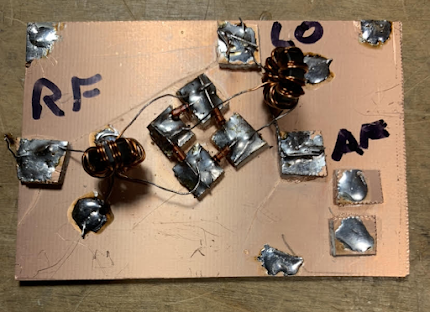
Manhattan Mixer Pads

Then it was on to the diode ring mixer.  We had planned on having the students wind their own trifilar toroids, but we realized that this might be too much -- it would add a lot of time to the build, and would introduce a lot opportunity for error.  

One of Farhan's transformers

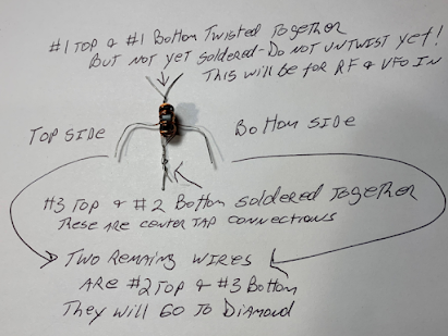
I remembered that Farhan had given me a big supply of FT-37-43 trifilar toroids that had been assembled in Hyderabad.  We decided to use these transformers.  We reasoned that this was not a big deviation from our DIY ethos -- after all, we didn't ask the student to wind their audio transformers, nor did they wind the RF choke in the VFO buffer.  But we faced a problem:   the Hyderabad transformers were all wound with the same color wire on all three turns.  This would make it hard for the students to figure out which wire went where (there were 12 such wires on each mixer board!).   I figured out how to do this:  The night before, I soldered together the center tap wires, and I twisted together the input coil wires.  We told the students to first solder the center taps in place, then solder the two free wires to the diode ring, and finally untwist the input coil wires, soldering in these connections.  This worked.  

How the transformers were prepped

Before we started, I gave the students a quick class on the essentials of mixers. And I pointed out that we were using transformers made in Hyderabad India and donated by our friend Farhan.  I told the students that whenever we include parts given to us by a ham radio friend we are adding "soul to the new machine." Indeed, Farhan's toroids added a lot of soul. 


We have been insisting that the students have each stage tested before moving on to the next.  This week we used signal generators to put RF and VFO energy into the mixers, and oscilloscopes to make sure that audio was coming out.  

One of the test set-ups for the mixers

The students are making good progress.  After today's session we did an estimate of where each of the projects stand at this point: 

We are building 15 receivers. 
Oscillation without the buffer:   11
Oscillation with the buffer: 5 
Mixer built and tested (but no diplexer yet):  5 
Mixer working, diplexer built  2

During the next month or so the students will build the bandpass filter and the audio amplifier, and put all the boards together to complete the receiver. 

Thursday, February 23, 2023

Early (1912?) Ham Station

 
Perhaps a bit overdressed by today's standards, but he's got a familiar look on his face.  Confidence and pride in his rig, and a steely determination to make contacts with it.  

If you zoom in you can see the crystal and the cat's whisker. 

More on this here: 

http://uv201.com/Photo%20Pages/ham_3.htm?fbclid=IwAR10Lbi2CAsYeiBDUjWb5KIQrh1SJVGwDyL2_1ZrkPk1VbllAUbeahwxsAI

Wednesday, February 22, 2023

The Transistor at 75, and the Raytheon CK722 (Pete's First Transistor)


https://www.eejournal.com/article/the-transistor-at-75-the-first-makers-part-1/

Part 4 is especially interesting to us because of the N6QW-CK722 connection: 

     Raytheon: Raytheon started making vacuum tubes in 1922. During World War II, the company made magnetron tubes and radar systems. Raytheon started making germanium-based semiconductor diodes in the 1940s and, just months after BTL announced the development of the transistor in late 1947, started making its own point-contact transistors using germanium salvaged from Sylvania diodes. After attending the 1952 BTL transistor symposium and licensing the alloy junction transistor patents from GE, the company quickly started making germanium transistors including one of the most famous transistors of that generation, the CK722, which was simply a rejected commercial CK718 transistor with downgraded specs for the hobby market. (Jack Ward has created an entire museum around the Raytheon CK722 PNP transistor.) Raytheon exited the semiconductor business in 1962.

Here are all of our blog posts on the CK722: 

https://soldersmoke.blogspot.com/search?q=CK722

Here is our post on Pete Juliano's CK722: 

https://soldersmoke.blogspot.com/2015/03/pete-juliano-homebrwing-with.html


Is this the Origin of the Term "Ham" Radio?

Click on the image for a better view

The timing (1895) and the context (railroad telegraphy) seem about right.  But other etymologies are out there.  Lexicographer Steve Silverman KB3SII is on the case.  What do you guys think?  Are the roots of "ham" radio in railroad telegraphy? 


Tuesday, February 21, 2023

Farhan's Direct Conversion Receiver

Thank God for the Wayback machine.  For a moment I feared that this article about Farhan's DC-40 receiver had been lost.  (Phonestack is now some Vietnamese vendor. ) But the WayBack Machine archive came through for us.  

https://web.archive.org/web/20171109081542/http://www.phonestack.com/farhan/dc40.html

Farhan's receiver has been covered on this blog before, but it is especially relevant for us now that we are immersed in our own direct conversion receiver project.  Farhan was working with his niece, who was a student.  We are working with high school students. 

I really like Farhan's blow-by-blow description of the build.  There are raw emotions here: He speaks of his hatred of LM-386s, and of how he thought of using the copper clad board as a projectile.  His niece wonders about the possibility of evil spirits in the receiver. The battle against AM breakthrough is very familiar.  (I like the RF choke idea.) You won't find candor like this in QST or QEX.  

Farhan's DC-40 project was one of the inspirations for our high school effort.  In fact, when we first went to the school, I left behind a direct conversion receiver that I had built.  Taped onto the bottom of the receiver was a quote from the DC-40 article and a picture of the Wizard of Hyderabad.  (See above, and click on the picture for a better look). 

This week we will inject some more Farhan-ismo into our receiver.  The time has come to build the mixer.  Like Farhan, we will go with the diode ring.   Winding the transformers would be very time consuming.   I remembered that on his visit, Farhan had left me a box of trifilar toroids wound by the seamstresses of Hyderabad using FT37-43 cores.  We will uses these in our build.  They will add a lot of soul to the new machine. 

Sunday, February 19, 2023

Antoine's Home Lab in Paris


Another very interestng lab brought to us by CuriousMarc.  


Saturday, February 18, 2023

Progress Report: High-School Students Melt Solder and Successfully Build Oscillators

Dean KK4DAS and I were at the high school on Thursday and Friday of this week for the construction (by the students) of the variable frequency oscillator stage of their analog, discrete, direct-conversion receivers for 40 meters.  Most of the students have already obtained their Technician Class licenses, so they are already radio amateurs.  Both the licensing classes and the receiver build are being done with the assistance of the Vienna Wireless Society. 

A week earlier Dean and I had demonstrated how to build the oscillator stage using the Manhattan technique (isolation pads super-glued to copper clad boards), but this week was the first time these students were actually building anything like this themselves. 


We deliberately did not "spoon feed" the students.  We told them that while we would be on-hand to help, THEY would have to do the building.  They would have to layout the pads on the PC board, select the parts (from a table set up by Dean), and do the gluing and soldering.  We did not hand the students bags of parts, or prepared PC boards.   This was not going to be a kit building session.  We wanted this to be real homebrewing. 

We had parts for 15 receivers.   But on the first day there were more than 60 students.  So four students per project.   On the first day we actually ran out of soldering stations.  

We cautioned the students against dawdling.  We told them to get on with it, and to "make haste slowly." We also injected an element of competition into the build by announcing that the first team to achieve oscillation would win.  (Prize still TBD).   

By the end of the Thursday session, many boards had been built but there were not yet any oscillations. We reconvened on Friday afternoon -- Dean and I set up support/troubleshooting stations. 

Right off the bat, one of the students came up with a board that he wanted to test.  After one quick correction (enamel still on the oscillator coil leads), my frequency counter showed that it was oscillating.  I fired up my DX-390 receiver and we heard the loud tone.   We had a winner! 

In the following hour or so, Dean and I did troubleshooting on about 10 more boards.   We found some of the problems that we would all expect (because we have all made these mistakes ourselves!): 

-- There were cold soldering joints.  We showed the students how to properly solder -- usually they just had to re-heat some cold-looking connections. 

-- A few of the Zener diodes and transistors were wired in backwards (been there, done that).  

-- A few of the feedback capacitors were of the wrong values.  Dean and I had brought some good caps, so the students were able to quickly swap out the parts.  This was another good lesson. 

-- There were a few wiring errors -- these were quickly corrected. 

It was exciting.  One-by-one we would hear the whoop-whoop as the DX-390 confirmed that another oscillator was OSCILLATING!  The students really liked to HEAR the oscillations that they had created.  We reminded them at the beginning that they would be taking DC from a little square 9 volt battery and turning it into RF that could (if connected to an antenna) be heard around the world, or in our case be used to receive signals from around the world.  

We got eight of the oscillators going.  We think the students will be able -- without much help from us -- to get the remaining seven oscillators going.  

They learned a lot.  They learned about the ease, flexibility, and usefulness of the Manhattan technique, and we think they could see how this represents a basic kind of PC board design.  Their soldering skills improved a lot. And they learned how to troubleshoot:  Is the layout correct?  Are any parts wired in backwards.  Is the soldering OK?   Are any of the parts bad (or of incorrect values)?  Most importantly, they learned that they CAN build circuits themselves, and actually get them working. 

The real payoff came each time oscillation was achieved. The students were really amazed and pleased.  I could tell that some of them weren't really sure their little device was actually creating the signal they were hearing.  So while we listened to the DX-390, I asked them to disconnect and reconnect the battery.  Confirmed.  Oscillation!  Smiles.   It was really great.  

Soon, after finishing up some PTO odds and ends,  we will move on to the other stages.  We'll probably do the bandpass filter or the mixer next.   Then the AF amp.  Then put it all together into a full receiver.  We think each stage will get easier and easier to build as the students learn and improve their homebrewing skills and their self-confidence. 

We've often reminded the students that what they are doing is NOT easy.  This is hard.  As new radio amateurs, they are taking on a project that most older hams never dare to take on.  They like the challenge.  They are homebrewing a real receiver. 

Friday, February 17, 2023

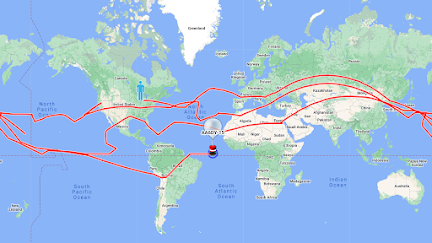
Ham Radio Pico Balloons Feared Shot Down by USAF


The Aviation Week article below helped to confirm some of my worst fears about the balloon thing.  For a long I've wanted to launch one of these balloons.  Recently I've been thinking about doing it from SolderSmoke Shack South (in the Dominican Republic -- they are BIG on party balloons down there!). 

https://aviationweek.com/defense-space/aircraft-propulsion/hobby-clubs-missing-balloon-feared-shot-down-usaf?fbclid=IwAR0ra3U4QPlzrNiVDNXz1UzQdDNfFUpccrQIRhVaCKkrZWHIPXQ0hwxEVKI

Check out Hans's site about the circumnavigators: 

http://www.qrp-labs.com/circumnavigators.html

Monday, February 13, 2023

The Infinite Impedance Envelope Detector (done with an FET)


Recently a fellow ham claimed that "envelope detection" doesn't really exist, and that the standard "rectification and filtering" explanation of how envelope detectors work (going back to Terman and beyond) is wrong.  But here is a good demonstration of the envelope detection of an AM signal.  It uses an infinite impedance detector built around an FET.  As Baltic Lab notes in the video above, the action is essentially the same as what happens with a vacuum tube:  The device is biased at cut-off.  The negative portion of the ENVELOPE is discarded.  The positive portion of the ENVELOPE is passed through the device and filtered.  What remains is the audio -- the same audio frequency that modulated the carrier.  ENVELOPE DETECTION.  

I was thinking about how fortunate we were that this form of detection was possible. Fessenden used what were in effect diode detectors to envelope detect very early transmissions of radiotelephony. If simple envelope detection via rectification had not been possible, radiotelephony might not have been invented as early as it was. 

Sunday, February 12, 2023

Mr. Carlson Replaces Old Capacitors -- Bathtub Capacitors


I recently posted a video from CuriousMarc about whether or not to replace electrolytic capacitors in old pieces of gear.  This is a hot topic in restoration circles. 

This week Mr. Carlson put out a video (above) in which he got rid of a bunch of "bathtub" capacitors in an old receiver. 

One of the many interesting things in Mr. Carlson's video was how his test gear initially showed the old capacitors to be good, but on further examination with better test gear he found them to be BAD! 

Out with old, in with the new!  

Friday, February 10, 2023

SolderSmoke Podcast #243 -- HI7/N2CQR, uBITX mods for 10 meters, High-School Direct Conversion Receiver Project Launched (Success!) Mailbag

 
DC RX and one of the PTO boards we built as demos last night. 

February 10, 2023


SolderSmoke Podcast #224 is available. 


http://soldersmoke.com/soldersmoke243.mp3


Video here: (32) SolderSmoke Podcast 243 (video) Hi7/N2CQR, uBITX, Success with High School Receiver Project - YouTube


Pete N6QW had technical difficulties this morning.  He insisted that the show must go on.  Pete will be back for the next episode. 


Travelogue: 

Bill in the Dominican Republic for all of January.  

HI7/N2CQR  Eastern tip of the island. uBITX and dipoles. 

20, 17, 10.  CW and SSB.  SSB was tough and I had reports of RF getting into the signal.

Went to CW. 

Worked VWS Mike KA4CDN, and Walter KA4KXX on 20CW.

Finally moved up to 10 CW.  Lots of contacts. Even though uBITX very QRP on ten.

I am modifying the uBITX now.  

Copper tape shielding to keep RF out.

 Low power out not the fault of the IRF-510s.  The problem is the 2N3904s.

Will replace with 2N2222 in To-18 cans.

Dean KK4DAS putting KD8CEC software into Arduino.  I gave up.

Who sent me this orphan uBITX?

SolderSmoke Shack South in final phase of construction.


SHAMELESS COMMERCE DIVISION:

Patreon!

Bezos Shopping!


DC Receiver Project

Local High School radio club. 

Simple:  Like Herring Aid 5 and Wes’s original.

Farhan’s four stages:

BP Filter, Diode Ring, PTO, AF amp. 

Simple Colpitts PTO SURPRISINGLY STABLE.

Simple and easy.  No chips.  No complicated circuits.

Guys have helped test out the design:  Rick N3FJZ, Walter KA4KXX,

Daniel VE5DLD, Stephen VK2BLQ and others. 

First session last night:  We demonstrated build of the PTOs.  

They worked (thank God).


Open Circuits book.

Envelope Detection Controversy

Save the Antenna – Book “Losing the Nobel Prize” K1JT


MAILBAG

--Dean KK4DAS 10 meter DSB!  Tiny SA ULTRA! FB

--John AC2RL on Elmer W3PHL DSB guy

--AC3K reports inventor of Fender Stratocaster guitar was a ham: W6DOE

--AF8E was doing POTA.  I worked him. He said my rig had presence. FB

--Alain F4IET FB DSB rig with mic in Cigar can!

--Daryl N0DP worked him on SSB.  He is homebrewing

--Steve N8NM was in for repairs but is on the mend.

--Rick G6AKG working with sub-harmonic mixers and logic chips

--Paul HS0ZLQ Built DC receiver but looking for something else to build. No DSB!

--Steve AB4I – Coherer, Jagadish Chandra Bose, and Marconi

--Eldon KC5U    Worked VK5QD right after me and mentioned SolderSmoke FB

--Todd K7TFC is building the DC RX.

--Tony G4WIF and Ian G3ROO using automotive relays for antenna switching. FB.

--Dave WA1LBP Great to hear from my fellow Hambassador (Okinawa)

Older post comments:

--Scott VO1DR was also in CF Rockey’s class! (Blog comment)

--Aurora Aug 4, 1972: Twelve people shared memories.  (Blog comment)

--Will WN1SLG Googled novice call and was led to my Novice log.(Blog comment)


Tuesday, February 7, 2023

VK2BLQ Builds the High-School Direct Conversion Receiver

It is truly a thing of beauty.  Stephen VK2BLQ built it just as we designed it, so his build (like those of several others) serves as confirmation that this design is ready for the high school students. 

Stephen writes: 

Bill,


Don't worry, you are not alone out there.

Here is my build; sorry that the front panel is overexposed and hard to see, but it is plywood.

I did follow the schematic but due to the contents  of the junk box there have been some component changes.

The only thing that I had to buy was the 3/16 x 50 mm (2 inch) brass screw.

My calculations for the coils for the PTO and  BPF  were  a little  bit off necessitating padding down the PTO with a further 100 pF (easier than remaking the coil and mounting)  and removing a few turns from the T50-6 toroids.

Like other people have found: the audio takes off at full volume; I am thinking but not yet tried adding decoupling between R5 (15K) and C2(47 uF). It isn't the actual values of the electros as I had to use 100 uF so might be the audio output getting back into the earlier stage.

The tuning range I get is  our 7000 to 7200 KHz and some shortwave stations above and below, Turning the screw is a little bit fiddly, but once tuned the vfo is quite stable and the audio sounds good.

Best wishes,

Stephen

VK2BLQ


I really like the ruler near the tuning control.  Is that (I hope!) the frequency readout? 

Designer: Douglas Bowman | Dimodifikasi oleh Abdul Munir Original Posting Rounders 3 Column