A while back Bob N7SUR got us talking about winter projects. Receivers. Of course, Pete and I quickly went down different paths. Pete is making great progress with lots of interesting digital circuitry. He is going over to the dark side. Check it out here:
I went with simplicity. Extreme simplicity. Direct Conversion (thanks Wes!). Discrete components. No chips. Analog Oscillator. 40 meters -- monoband.
 |
| Schematic updated 29 November 2017 |
There it is. You can click on the picture to make it larger. Here is an outline of the circuitry:
-- Single tuned circuit bandpass filter preceded by a simple pot that serves as a gain control.
-- JFET RF amp
-- Singly balanced passive mixer inspired by F5LVG's RX-20 in SPRAT 100. For the coil I used one of the many trifilar toroids that Farhan gave me.
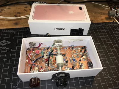
-- The local oscillator is the coolest stage. I used a 7.37 MHz ceramic resonator and a circuit inspired by Miguel PY2OHH. With a polivaricon I can tune the entire 40 meter band. I put a reduction drive int here to make tuning easier.
-- The AF amp is an op-amp free design. It works well into ear buds or into a computer speaker.
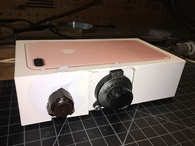
-- Perhaps in an effort to catch the attention of the younger generation, I built it into an iPhone box.
Please let me know if you spot any flaws in the circuit, or see any places where it might be improved.
More to follow. This prototype is now in the mail, en route to my nephew John Henry who will be testing it for me.


Hi Bill.
ReplyDeleteSimplicity is perfection. Absolutely a stunning project. Very nice indeed. John Henry will have a lot of fun with that rig.
I smiled a bit when I saw inside your box. In case some of the youngsters in our hobby don't recognize one of your key components -- the interface between your reduction drive and the tuning cap is an insulated shaft coupler that is good for about 10 KV. The metal coupler typically which would accommodate a 1/4 inch shaft (some were 3/8 inch) is bonded to a chuck of ceramic. The length of the ceramic portion is in direct proportion to the insulation rating --the more ceramic the higher voltage rating. These insulated couplers were made by companies like National and Millen.
Thus not only does your creation have a simple fundamental approach to a direct conversion receiver but it the addition of the insulated coupler add real "soul" to the rig.
Speaking to your design -- it is anything but just a simple DCR -- it is a very sophisticated design embodying many refinements that address some of the general DCR short comings. Just looking at the schematic --this is one FB design and certainly will perform well.
Bravo Bill and hopefully John Henry has a real appreciation of what is inside the box.
73's
Pete N6QW
Of course I spotted a flaw in the circuit. I didn't invent it! (turns light green with envy)
ReplyDeleteOf course I spotted a flaw in the circuit. I didn't invent it! (turns light green with envy)
ReplyDeleteExcellent!
ReplyDeleteThis is an example of something that children and cats are well aware of: Playing with the box is more fun than what came in the box originally. We sometimes lose sight of that in the course of the human maturation process.
73 - Steve N8NM
Thanks guys. Hey Pete: Thanks for he info on the coupler. I just pulled it out of the junk box (actually out of a regen receiver -- no great loss!). And I just realized that this adds even more CERAMIC to the rig. FB. It also takes care of hand capacitance. Completely.
ReplyDeleteSteve: I hear you on the boxes. Christmas is a coming!
73 Bill
Bill,
ReplyDeleteThanks for your efforts with the show and blog, enjoy them immensely as an aspiring radio builder (otherwise experienced electronics hobbies/enthusiasts just getting into Radio/RF building/learning the tricks and absorbing the tribal knowledge). Will appreciate if you can share the circuit source, like to play with it a bit, simulate blocks with Spice, and maybe get motivated to lay out a board in KiCAD to send to OSHPark or similar.
73 de kc1ccr
Hi Bill,
ReplyDeleteNice simple design. I have one question:
The mixer diodes seem to have no conduction path to ground. How does LO current pass through the diodes to turn them on\off? Seems like there should be a resistive load at the mixer output to develop that current, otherwise the mixer will collapse on anything except very weak signals.
Joe
W3JDR
In thinking about it, it seems that the transformer secondary needs a grounded center tap and the LO injection point should be on the other side of the diodes. Can you point to the original article where operation of this mixer might have been discussed?
DeleteJoe
Joe: The circuit is from SPRAT 100. But there is no real discussion there. I realize that it looks different from the standard two diode mixer circuit. But I don't think you NEED that center tap. They usually have the center tap as a way of introducing the AF signal in a balanced modulator in a non-differential way -- to have the same AF signal hitting each diode. But here the 1K pot performs that function -- the LO signal turns the diodes on and off. The RF signal from the antenna is the one that is balanced out. Audio mixer products on to the AF amp. I'm listening to it right now. It works FB and knocks down all AM breathrough. 73 Bill
ReplyDeleteI don't understand how the mixing takes place without LO current in the diodes, but apparently it does. I'd love to hear an explanation. One possibility is that it's happening in the output of the LO buffer - kind of far fetched though.
ReplyDeleteJoe
Joe: Very cool that we are trying to understand this mixer. I modeled it in LTSPICE and it works well there. I think it helps to look at it this way: The simplest of product detectors use just ONE diode, with the LO AND the signal going into the same side; resistive load to ground on the other side of the diode. LO turns the diode on and off; signal goes through when diode is on and mixing action occurs. The F5LVG circuit is that, but sort of in push-pull. In my circuit the load is provided by the 100K resistor to ground via the 100uF cap. LTSpice is very illuminating on this mixer. Please take look at it in LTSpice and see if you think I'm on the right track. 73 Bill
ReplyDeleteBill
DeleteI can see a way it might produce mixing products if there were a way for the ground referenced LO to force switching currents through the diodes in the floating secondary path of the transformer, but I'm not seeing it. I can see how this mixer could produce some mixing products by square law properties of the diodes, but it seems to me that it would collapse with moderate to strong signals.
Be assured I won't rest until I've modeled this and understand it thoroughly. I do this kind of work when I arrive in the office early, about an hour before anyone else is there, so I'll try to get,to it tomorrow. I'll do a little write up when my investigation is complete.
Joe
Excellent Joe. There aren't a lot of people who -- like us -- worry about this kind of thing. These circuits are a lot more fun to use when you really understand them. I'm not quite there yet with this one, but I think we're getting there. As for the diodes, I think the LO alternately pushes, then pulls current up through the cap and the resistor to ground on the other side of the diodes. LTSpice helps a lot. Look forward to your write-up. I also wrote to F5LVG, asking for some background on the circuit -- I will let you know if I hear from him. 73 Bill
ReplyDeleteBill
ReplyDeleteI modeled everything from the input preamp through the mixer post amp and, sure enough, virtually nothing. I then moved the resistor divider to the output side of the diodes with the divider midpoint to ground, went to a center-tapped xfmr and drove the LO input to the CT. Remarkable increase in overall gain.
FYI, F5LVG fraws this circuit differently in different writings; in one case like you have it and in other cases like I described. I think the one you're using is a mis-print and is wrong. That's why I asked for signal generator tests. My guess is your receiver, though it seems to 'work', is relatively deaf.
My Error in my previous:
DeleteI actually drove the LO into the midpoint of the voltage divider and grounded the xfmr CT.
Joe: I don't know. With the F5LVG SPRAT 100 configuration, in LTSpice I get a nice 1 kHz audio sine wave out of the mixer with a 2.4 mV peak with 1 Vpeak from the LO 7100 kHz and .01 volt 7101 kHz going into the JFET preamp. The actual receiver is quite loud with this configuration. I can hear the band noise when I connect the antenna. I had to put an RF gain control in because it was so loud it was hurting my ears. So deafness is not a problem. And it sounds good.
ReplyDeleteIn LTSpice I tried the circuit you recommended -- moved the pot to the other sided of the diodes, put a center tap on the coil, grounded the center tap and fed LO into wiper of the pot. I couldn't get it to produce audio in LTSpice.
I wrote to F5 LVG to ask him to see if the SPRAT article had an error. But I think it is OK. Again -- imagine this circuit with just ONE diode. With LO AND RF going into the same side of the diode and output taken from a resistor across the other side of the diode. They actually do that in some very simple SDR receivers. I modeled it in LTspice and it works there too.
This is fun. We will get to the bottom of this. 73 Bill
Bill
DeleteIf you put 10 mV in and got 2.4 mV out, you had about 12 dB loss. In my souped up comfiguration, I get about 45 dB conversion gain, from RF in to output of the mixer post amp, with 2 fewer parts. Can you send your LTSPICE file to me so I can see where we differ?
This comment has been removed by the author.
Delete...also,
ReplyDeleteCan we continue this interesting dialog via direct email? My address is:
Joe
At
Roccis
Dot
Com
This is commenting way late, but...
ReplyDeleteIsn't the LO current path AC-coupled from the center of the pot, through whichever diode is forward-biased, and then grounded through the 0.1uF cap at the junction of the diodes? Then the RF path has its polarity reversed each half-cycle of the LO because of the reversal of forward-conducting diodes, causing the mixing products to be generated.
Anyway, that's how I see it. My brain would prefer to see a DC path, but I'm not sure it matters as long as the AC reactance is low enough.
This simple design has such powerful features, the blogger is a genius
ReplyDelete