Just go to http://soldersmoke.com. On that archive page, just click on the blue hyperlinks and your audio player should play that episode.
http://soldersmoke.com
Lock-down is bad enough, but now we will also have to cope with the feelings of homebrew inadequacy that Peter's rigs always cause. But look on this as an opportunity for inspiration. Peter once again raises the bar.
I'm
just listening to the latest podcast and note your returning lovefor AM
Broadcast stations and wondered if you also see the trend in the US that we are
seeing in Germany?
I
know you have WTWW but that's a commercial SW AM Broadcast radio station, that
has always been owned and run by a family of Hams. What we are seeing Germany
is that when a commercial broadcaster such as Deutsche Welle closes down their
Shortwave Broadcast stations, Amateurs are applying for and getting licences to
the freed up frequencies. This started about 5 years ago with channel292
(Channel292.de) on initially 6070 kHz and then later also on 7440 kHz.
This amateur is located near Ingolstadt in Bavaria and runs 10 kW using the
driver stage from the old DeutscheWelle 100 kW transmitter on the same
frequency. He is partnered with a group in Austria who run a major AM station
near Vienna that has two 500 kW transmitters and some fantastic massive antenna
systems with 20dB gain across the whole of the HF spectrum. That Austrian
station is still owned by the Austrian government in case they need a broadcast
station to transmit around the world at any time. It's kept "idling"
at 100 kW in the meantime and like Channel 292 includes the German language "DARC
Radio" amateur radio program in what it transmits.
New
on the scene is "shortwaveradio.de" - Yes the station name is the same
as their web address. They currently run just 1 kW into an Inverted-V wire
antenna on 3975 kHz (in the 75m BROADCAST band over here) and 6160 kHz in the
49m broadcast band. As they are located
in North Germany, I don't get much of a signal from them down here in the south
and the recording is using a WebSDR receiver. Their dipole is orientated to
cover the Benelux countries and the UK. The lads at this station are always
looking for English content, so if you want part of Soldersmoke to be
transmitted on a shortwave AM broadcast station, (as you mentioned in the
latest podcast) I can easily put you in touch with them.
One
more for the list could be Radio Caroline in the UK. The station, which once
was the main pirate radio station off the coast of the UK is now a volunteer
historic preservation society (with some radio Hams involved) who have been
granted a local radio service licence using a frequency (648 kHz) and
transmitter site previously used by the BBC world service! Their old nemesis ! (http://www.radiocaroline.co.uk/#home.html )
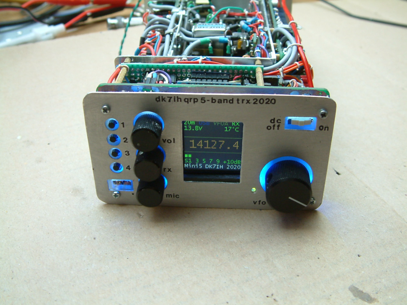
And that, my friends, is a HOMEBREW transceiver. Wow, amazingly well done. After I showed this to Pete N6QW (no slouch in the homebrew packaging department), in frustration with his self-perceived shortcomings he threatened to give up on homebrewing and to throw away all his rigs. Don't do it Pete!
Peter Rachow, DK7IH has carefully documented his project through as series of blog posts:
Don't be deterred by the lack of English subtitles -- radio amateurs around the world will be able to follow what is going on in this very interesting 1955 film. It is only about 14 minutes long. This video takes us back to a time when hams were hams and rigs were RIGS! Note the German OM who apparently slept fully dressed (with necktie) in order to be ready to spring into action on the ham bands in the middle of the night. That's dedication my friends. Also note the fellow sending out QSL cards that feature the schematic diagram of his rig. Lots of solder melted in 1955. Great stuff. Thank God for the Heaviside Schicht!
I was especially interested in the rig pictured above. NOTE: NO GLOWING NUMERALS. That rig has an analog VFO. The blog article provides some great pointers on how to achieve thermal stability. Also, be sure to check out his "Old School" rig.
I've put Peter's blog in the blog listing on the right side of the SolderSmoke blog.
Take a look at that beautiful rig in the bottom of the cover pictures. (A closer shot appears below.) That is an HRO dial, right? Or is it? No, it is not. In the picture we see the homebrew receiver designed and built during the 1960s by Rudolf Fishcer, DL6WD. It is magnificent in every respect. Because I have been working with the HRO dial and gearbox given to me by Armand WA1UQO, the tuning dial on this receiver caught my attention. Here is what DL6WD says about this part of his project: "The main tuning gear was built around a BC-221 tuning capacitor and reduction gear. The counter dial and tuning knob are the result of four weeks of labor, The counter dial reads in tens of kHz, where the main tuning knob has a calibration of 200 Hz per division, from an HRO inspiration." The counter is in the little window to the upper left of the tuning knob. The window to the upper right is a phase-lock indicator. (See below.) By the way, by the time DL6WD got finished with this all solid state receiver it weighed in at 52 pounds. Rudolf noted that "excessive shielding pays in electrical performance, but not in weight!" DL6WD earns the title "Homebrew Hero."
I understand the launch of Farhan's CubeSat has been delayed a few days. That's the way it works in the rocket launch biz --patience is required. In the meantime, I've been practicing with my receive system. Today at 1000 local the Max Valier satellite flew to my west. It rose 78 degrees above my horizon to the W NW. I left my three element quad pointed in that direction and waited for the satellite (which had been launched from India) to fly through its pattern. The CW beacon was quite strong, very visible and audible through my RTL-SDR dongle and HD-SDR software. You can see it and hear it in the video above. There is something quite charming about this very personal Morse message coming down from orbit and then passing through all that digital technology. More info on the satellite:
"Max Valier Sat" is an amateur satellite built in cooperation by:
"Max Valier" High School in Bolzano/Bozen (Italy)
OHB System AG from Bremen (Germany)
Max Planck Institute for Extraterrestrial Physics from Garching (Germany)
Its main payload is an X-Ray telescope devised and made by MPE. Data generated by this detector will be transmitted, together with housekeeping data, over an amateur radio link with frequency 145.860 MHz.
A second payload is an amateur radio beacon transmitting a message in Continuous Wave. The beacon's frequency is 145.960 MHz
"Max Valier Satellite" was launched by the Indian Rocket PSLV-C38 on June 23, 2017 at 9:29 am IST (05:59 am CET) from Satish Dhawan Space Centre.
This past weekend I dusted off my old scratch-built, all-analog, no-chips BITX20. (THREE CHEERS FOR FARHAN AND HIS BITX DESIGN!) I hooked it up to my trusty CCI .1KW (note decimal point) amplifier and my new 135 foot store-bought doublet. This all happened just as the Worked All Europe DX contest was kicking off, with lots of activity on 20. TRGHS. I was in. My contest operating style was in the category of "relaxed-casual-noncompetitive." I took a lot of breaks. In fact there were more breaks than non-breaks. You have to pace yourself in the contest world. My results: 8 SEPT: DF0HQ,
SN7D, GM6X, DP6A, S51A, DL0HN, DB0HX, OZ5E, DJ5MW, HG7T, IK4UPB, VY2ZM, G6XX,
EF1A, LZ5R, 9A5W, YP0C, F6HQP, DL7ON, HB9DQL, ON6NL, DA0WRTC,9 SEPT: EI7M, P3X, RU1A, DP7D, SP2KPD, DL0WW. P3X might not count because, you see, Cyprus is considered to be in ASIA. Really? Anyway, I 'm assuming that I am the winner in the homebrew, discrete component , all-analog transceiver category. Woo Hoo! The contest rig is pictured above. Before you point to the glowing numerals and cry foul, realize that the little Altoids box between the two speakers holds a San Jian frequency counter that was deliberately kept OUTSIDE the BITX box. So it is more of an outboard accessory. I can run the BITX 20 without the digital assist -- I have an old fashioned non-digital dial pointer to indicate frequency. The "Low - High" switch you see switches the VFO from the low portion of the 20 meter phone band to the higher part of the band. The box below the BITX 20 holds the uBITX. Seriously though, I was quite pleased with the performance of the doublet.
SolderSmoke Podcast #200 -- TWO HUNDRED!!!!-- Is available http://soldersmoke.com/soldersmoke200.mp3 -- Old friends on 17 meters. -- Another Knack Nobel in Physics. -- Hans Summers' QCX transceiver: $50 IS THE NEW 10 GRAND! -- New Bands! 630 and 2200 Meters. BIG ANTENNAS! -- Nuke Powered QRP. No joke! -- The Challenge of UHF. Not for the faint of heart. -- Reginald Fessenden, Father of Phone. PETE'S BENCH REPORT: The New Simple-ceiver. Soon to be a Transceiver. BILL's BENCH REPORT: Discrete, Direct Conversion, Ceramic Receiver in iPhone Box. THE EDUCATIONAL PORTION OF TODAY's PROGRAM: HOW TO TROUBLESHOOT A HOMEBREW RECEIVER. MAILBAG.
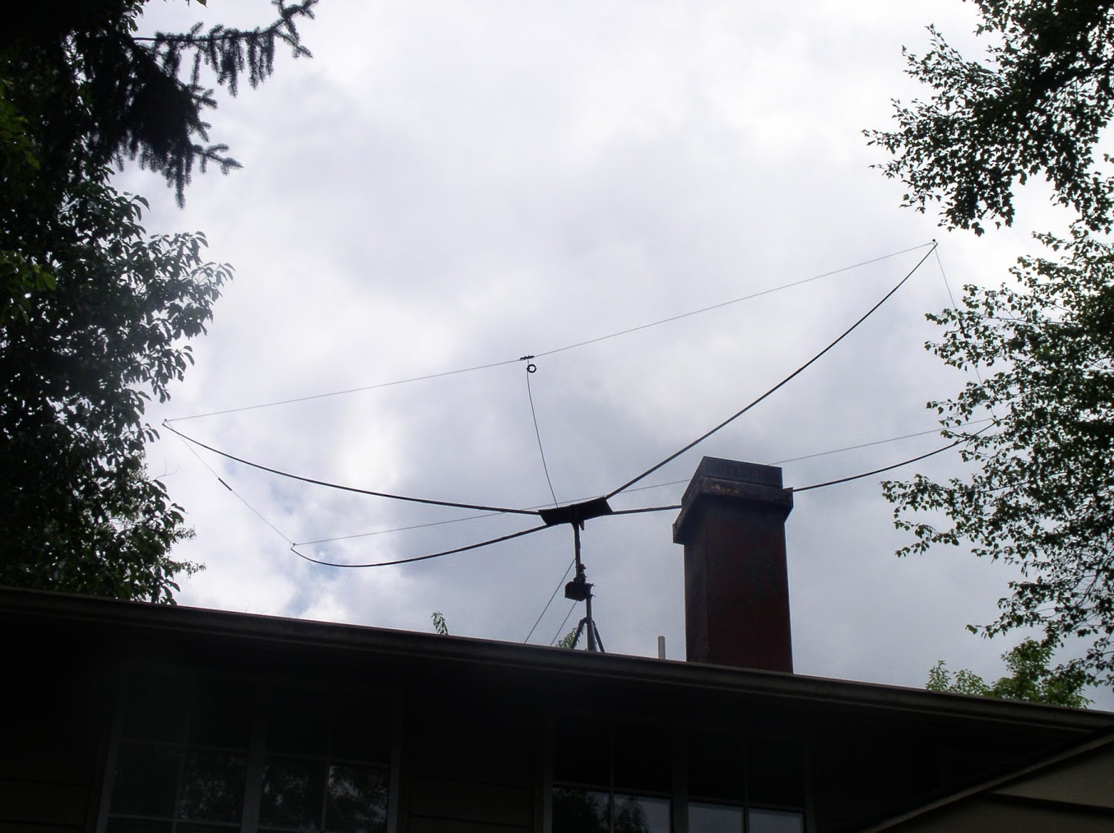
I had a very nice contact on 17 meters yesterday with Jan DL1YC. It was a rare Moxon-to-Moxon contact, with homebrew 17 meter Moxons on either end. Jan's is a bit cooler than mine: His is flat, without the "blownout umbrella" support that we see in mine (below) and in the Hex Beams. Jans told me that he achieved this flatness by starting out with very long telescoping fishing poles -- he discarded the the thin portions of the pole and used only the more rigid pieces. (I used 16 foot, 5 piece Shakespeare Wonderpoles from Amazon.) I think he also used thin wire for the elements. The crossbar that you see in the picture above is there to support a balun at the feed point -- without the cross bar the balun and the feedline would cause the balun to droop. I couldn't resist a little front to back testing. Jan's antenna does not have a rotator -- he used the "Armstrong" method of antenna pointing. I didn't want to make him go outside to spin the thing around by hand, so I just turned mine and asked him to take note of the difference front to back. He saw 3 S units. 18 db. Not bad. Jan said his antenna weighs about 8 pounds -- mine is very similar at 9 pounds. Jan expressed some concern about UV deterioration of the fishing pole fiberglass. Mine has been up there three years without any problems. Like me, Jan had considered "nesting" an element for another ban (perhaps 20 or 12) but -- like me-- had concluded that this would be too difficult.
At the instigation of Bob N7SUR I've been working on a simple, easy-to-reproduce Direct Conversion receiver for 40 meters. I'm building this for my nephew John Henry, and I'm hoping this will be a circuit that others can use to break into the ELITE corp of successful ham receiver builders. Coincidentally Joh in Freiburg Germany is working on a very similar project -- we have been comparing notes. At first I used an FET detector described by Miguel PY2OHH. It worked, but at night the AM detection of powerful shortwave broadcast stations drowned out the amateur signals. So Joh and I started to explore detectors that would eliminate this problem. I went with a version of one described in SPRAT by F5LVG ( "The RX-20 Receiver"- see below). Very simple: A transformer to two back-to-back diodes with a 1K pot to balance the signal from the VFO. OM Olivier used a very, very cool transformer: he took two small, molded chokes and simply glued them together! 22uH choke as the primary, 100uH choke as the secondary. I went with one of the toroidal transformers that Farhan left me when he visited in May. I'm using a varactor-controlled ceramic resonator VXO (no Si5351 in this one!) and a non-IC AF amp designed for use with ear buds (the world is awash in ear buds). It is a "singly balanced" design with the incoming RF signal being the one "balanced out" in the detector. Last night the receiver passed the AM breakthrough test. The SW broadcast monsters were balanced out and kept at bay. This morning the receiver passed The Boa Vista Rooster Detection Test. I fired up the receiver and heard an operator speaking Spanish with a Brazilian accent. When I heard the rooster crowing in the background I knew it was Helio PV8AL from Boa Vista Brazil. TRGHS -- this little receiver is a winner. I'll try to post a schematic soon. And hey -- look at what wonderful IBEW (International Brotherhood of Electronic Wizards) project this is: Instigation and inspiration from Oregon. Some design ideas from Brazil. A French detector circuit described in a British QRP magazine. A transformer from India. A collaborator in Germany. And finally, the rooster of Boa Vista.
Let's not forget Wes Hayward W7ZOI for bringing back (in 1968!) the neglected Direct Conversion idea.
Pete WB9FLW alerted us to the work of Peter DK7IH, a very talented homebrewer who recently followed the lead of Pete N6QW in building some really small SSB transceivers. Here is his Micro QRP SSB rig:
You can see more of his fine work here: https://radiotransmitter.wordpress.com/ https://www.qrz.com/db/DK7IH Have you guys noticed how many Peters there are among homebrewers, especially among SSB homebrewers? Just from recent mentions on this blog: Pete Juliano N6QW Pete WB9FLW Peter Parker VK3YE Peter DL3PB Peter W1UO Peter GW4ZUA Peter G6GNR Peter VK2EMU Peter VK2TPM Peter HA5RXZ Peter DL3JIN
There is a lot of radio history in this shortwave transmitting station. I came across it tonight with my BITX DIGI-TIA rig. It was on 7.215 MHz transmitting in Indian (South Asian) languages. But alas, the signals were not from distant India (home of the BITX!). Instead -- as often happens these days -- the signals were from a relay station. In this case they came from relatively nearby Germany, from the Nauen transmitter site. Check out the Wikipedia page: https://en.wikipedia.org/wiki/Nauen_Transmitter_Station
In spite of being a bit off frequency, sTef, DL1FDF (aka VY1QRP) has been inducted into the Color Burst Liberation Army. Congratulations sTef! Normally we would requite operation on 3.579 MHz, but sTef has been granted special dispensation because 1) he doesn't have a 3.579 MHz rock, 2) our stock of this crystal has been depleted, and 3) he actually made a contact with this rig, working II3ICZ in Venice. FB sTef. If anyone has a color burst crystal for sTef, please let us know.
sTef writes:
I would like to say „Thanks" to both of you for your ongoing inspirations in soldering and homebrewing. After 15 years out of ham radio it were you two guys who got me back into the world of -> SOLDERSMOKE. Thanks for that.And belive me been away for 15 years and now getting back into it feels a sometimes a little bit too "digital“ …. ARDUINO or NOT TO ARDUINO ? This is the question….
Anyway…
So what could be more sophisticating than having a MMM ready on the work bench and answering a CQ call on 40m with that thing and be heard.
Yes, the first QSO today with my MMM was for you both.
I worked the Italian Radio Station II3ICZ. I was 559 into Venice with 0.5 watts from the MMM into my full-size triple leg for 40m.
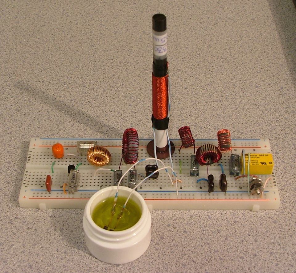
The saturable magnetic frequency septupler. The tiny computer memory core is submerged in olive oil (Italian...naturalmente).
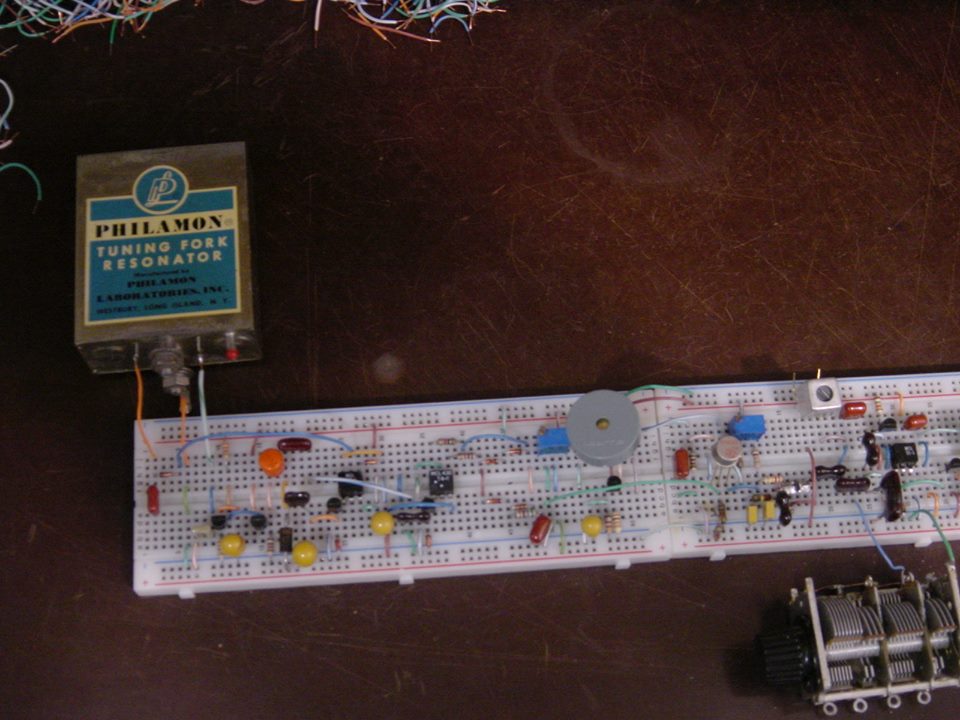
Not a very good picture, but here's the 1600Hz tuning-fork, fork oscillator, SRD pulse generator, PLL S/H phase-detector (diode gate), differential amplifier D.C. amplifier, and part of the 500kHz VCO.
I was pleased to have made the first contact with my tuning-fork transmitter this evening. My contact, N1QLL, runs a pretty B&B on the Maine seacoast, midway between Bar Harbor and Cutler. Jerry was operating a solar-powered QRP station. I found a follow-up email from him when I came up to the house for dinner. He's asking for a better explanation of my set-up. I can't wait to tell him about the passive frequency septupler made from an East German computer memory core, heat-sinked in a thimble of olive oil.
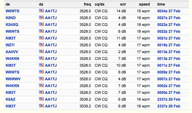
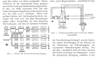
My signal was also logged by a number of automated "Reverse Beacon Network" receivers (image attached) located in Ohio, North and South Carolina, Virginia and Pennsylvania...not bad for 90mW on 80m. Please note that my operating frequencies, 3,528.0 and 3,539.2kHz, are the 2,205 and 2,212th harmonics, respectively, of my 1,600Hz tuning-fork frequency reference. FYI: the third attached image illustrates the block-diagram and tuning-fork reference oscillator circuitry for three common-wavelength AM broadcast transmitters operating in Berlin, Stettin and Magdeburg, Germany from 1928 through the mid 30's. A central 2,000Hz tuning-fork generated reference carrier was transmitted by landline to transmitters in the aforementioned cities whereupon the 529th harmonic was generated, amplified and broadcast at 1,058kHz. The equipment was designed by the Berlin-based firm, C. Lorenz A.G.. The fourth image details Lorenz' technique of frequency multiplication via saturable magnetic iron-core inductors. My septupler operates in an identical fashion. A very pleasant day...
Mike points out that this is a work in progress. He hopes to cross the pond (the Atlantic!) soon. Here is a update from Mike: A nasty cold has delayed work on the 20 meter implementation, although some of the time I've spent crashed on the sofa was put to use redesigning the loop filter network. I think yesterday might have been my "hump" day so I'm looking forward to getting in some quality bench-time over the weekend.
By the way, my PLL-based transmitter frequency stabilizing circuit has much in common with a garden-variety frequency-synthesizer. Obviously, the tuning-fork frequency reference is the main point of departure. My sampling phase detector, for example, was old hat by the mid-1960's. Nevertheless, this has been a fun project.
This is almost enough to make me abandon my analog, discrete component, HDR fundamentalism. Check out that display. And that StereoAM mode in which the upper and lower sidebands go to the left and right headphones "useful for CW"... Wow, that's seems like a step beyond binaural.
Don't miss Parts 2-4 --They are all on YouTube and will appear in the right hand column when you are watching Frank's videos. But I couldn't resist embedding the video that shows the hardware. Note: the oscillator is an Si5351! Yea! And the LP filter board comes from Hans Summers.
Beautiful work Franz! Thanks for making the videos. 73 Bill
Michael updates Peter (and us!) us on his efforts of this week:
Grüss Peter!
Thanks for the nice message. Yes, I knew that you were going to be QRV with your ZnO transceiver but I never heard if you had made any contacts. I guessed that you had not, otherwise I'm sure you would have let me know.
Again, I think your circuit looks really great! It's amazing to think you managed to squeeze 500uW from a scrap of oxidized zinc-plated steel. Even if you didn't make a contact, what you are doing is really fantastic. Congratulations on the creation of this amazing radio!
Okay, so I spent most of the afternoon at the workbench. Thus far I'm only using a single SRD (step-recovery-diode...1N5401 rectifier). Of course the result is a unipolar pulse. The idea did work as planned, however the power only increased by 2.24dB. The maximum RF output power is now 230uW. At least the SRD makes a pretty pulse :-)
Please find two scope captures attached to this message. The first (0002) shows the SRD generated unipolar pulse. As you can see, the pulse width is nearly perfect for the job. The second trace shows the output RF waveform. The worst spurious energy is ~20dBc. The second image shows the 507kHz waveform at the unijunction emitter along with the output RF waveform.
The beacon is presently off the air, but I look forward to trying my luck tomorrow with a back-to-back pair of SRDs. A bipolar pulse pair will provide a shock impulse once every 3.5 cycles, instead of once every 7 cycles with the present unipolar drive pulse. The bipolar pulse pair should result in increased RF output power as well as a slight spectral improvement.
It's only a matter of time before you make a ZnO QSO, Peter. As we always say, the difficulty merely sweetens the eventual success.
A broadband measurement of my output power (using an AD8307 log-amp power meter) indicates 139uW. Spurious frequency energy accounts for 2uW, leaving 137uW at 3.552MHz. I believe this is roughly the output power produced by your ZnO transmitter?
This morning I'll attempt to increase the unijunction (UJT) 80m RF output power by inserting a pair of back-to-back standard-recovery power supply rectifiers (1N5401-ish) at the UJT base-2 to ground node. Thus far I have relied exclusively on internal UJT nonlinearity for the generation of harmonic energy. I've reason to believe the minority carrier charge-storage capability (normally a defect, but hopefully a virtue here!) of these rectifiers will efficiently produce a bipolar pulse-pair every 1/500kHz seconds resulting in an odd-order comb-spectrum. At least that's the plan...we'll see how it works out ;-)
Peter, I never heard the results of your ZnO DXpedition? Any luck OM?
Okay, I'm off to the Hobbit-Hole. My heartfelt thanks to you all for your shared interest in this cock-eyed project.
73,
Mike, AA1TJ
Peter, DL3PB, in Germany respond with amazing news of his own. Peter is homebrewing his own tunnel diodes, using Zinc Negative Resistance Oscillators. No store-bought appliances for him!
At this point you really have to visit the pages of Nyle K7NS
Nyle tells of building a little microwatt transmitter, and, once the snow melted, climbing a hill 5 miles from town to see if he could hear it. This reminded me of young Marconi's early efforts in Bologna.
Peter writes:
Hi Folks,
Mike, your plan on how to increase output-power sounds reasonable – yes, a few dB could really help, to make reception a bit steadier and thus allow a QSO.
Well, I thought we had already talked about the ZnO TRX attempt, but obviously we didn’t. The reason is dead simple - It didn’t work.
[ The ZnO TRX is a minimalist 80m band transceiver with a homemade tunnel-detector-diode as the only active device – based on Nyle’s K7NS experimentshttp://sparkbangbuzz.com/zinc-osc-2/zinc-osc3.htm – please find attached an early schematic ]
Three days in a row after Xmas I tried for several hours each, I had announced the activity on QRPSPOTS and the German QRP Forum. Thus several guys within the right distance were really trying hard to copy. I used different temporary antennas, mostly verticals, but also a sloper dipole - nada, niente , nothing. One or two OMs reported weak CW signals on the scheduled QRG, but too deep in the noise, to even make out, whether it was me or someone else.
Yes, power is more or less comparable, actually it’s 0.5mW +/-3dB depending on the day’s form of the homemade tunnel-detector, but I guess all my antennas are some dB behind a full-size dipole, so at the end it’s pretty much the same.
Folks were very cooperative during the test itself, but after it was clear, that it had not worked, the usual trolls showed up to explain, why that never could have worked... I plan another test within the coming week e.g. during the PA-contest next weekend ( I’m only 30km from the dutch border ) with a base loaded 15m vertical – be assured, you’re the first to hear about any success in terms of QSO or just being heard anywhere.
What would we go for, if everything works as expected and/or right from the beginning – or as Jim said it : What fun...
73!
Peter/DL3PB
Finally, Alan Wolke provides a very illuminating (as always) explanation of tunnel diodes):
"SolderSmoke -- Global Adventures in Wireless Electronics" is now available as an e-book for Amazon's Kindle.
Here's the site:
http://www.amazon.com/dp/B004V9FIVW
Re: Can not upload pictures to For Sale section
-
Glad to know I'm not the only one with that problem Mark. I tried to upload
a PDF file in the Technical forum and was met by the same message. I sent
JN a ...
May 2, 2024. The Choices We Make.
-
There is absolutely nothing exciting about today's blog other than to share
a bit of musing I did yesterday.
The occasion was sitting at the Board and C...
CEPT: Using a US callsign in Germany?
-
Many thanks to Spencer (WD4AWD) who writes: Hi Thomas, [I] know you’ve
operated abroad a number of times, in some cases with a country-specific
call (UK, f...
Conversion of NOELEC style balun board to 1:1
-
This article describes a small 1:1 balun for use in measuring field
strength using his TinySA Ultra and a small loop antenna. The balun is also
useful for ...
Frans puts his new KiwiSDR2 on the air and online
-
Many thanks to SWLing Post contributor, Frans Goddijn, who writes: Dear
Thomas, Last week I bought & installed the new KiwiSDR receiver and shared
it on th...
An Inline RF Step Attenuator for QRPp Work
-
I don’t need to explain the attraction of low power operation; if you’re
reading this, the chances are that you are already a convert. I’ve been
operating ...
A 51S-1 Restoration Story
-
I came across my Collins 51S-1 in a big junkyard in Ankara, Turkey around
2012. It was in a pile with a lot of other electronic scrap, probably from
one o...
New QRP Cluster Online From OM0ET and OM6APN
-
By DX EXPLORER
DX EXPLORER
Paul OM0ET and Peter OM6APN recently launched a new cluster dedicated to
QRP operations. Have a look and I hope you will enjoy...
3D Printing The Hadley 114mm Newtonian Telescope
-
Yes, we’re building a 3D Printed Newtonian Telescope called Hadley. It’s
being printed in PETG and in the video below, I give a quick tour. My build
isn’...
3D printed project boxes
-
I have been busy with some other things that have kept me away from
electronics projects for quite a while. Now I can get back to them, but
realize I n...
Daylight Again – An all Analog Radio
-
What’s all this? In 10 seconds, A high performance, 7MHz, 5 watt SSB rig
Draws just 24 mA of current 90 dB dynamic range, 80 dB close-in dynamic
range 3D ...
Adding Enclosure to your sBitx Boards Order
-
The early buyers of the sBitx board set who bought it for $270 USD might
want to also add the enclosure (box) for in the kit. What you will now get
is a f...
Digi-chirp! Digital synthesis of ‘nostalgic’ CW
-
The bottom ends of 80, 40 and 20m are not what they used to be. For
starters, the busiest part is the digital segment where computers talk to
computers – l...
-
A Simple Speech Processor
(For QRP/SSB Homebrew Transceivers )
Over the last few weeks I had been thinking to build a small AF speech
processor to add to...
A New Look for your uBitx!
-
Adding a "Cool Blue" Display to your uBitx!
The standard "green background" with black lettering frequently reminds me
that I suffer from Chronic seasickn...