


In the video above (from 16 years ago) we see Jeff Damm, WA7MLH's band-imaging receiver for 75 and 40 using an IF of 1.750 MHz and a VFO of 5.2 - 5.7 MHz, For a signal at say 3.579 MHz (!) you subtract the signal from the VFO and you end up at the IF. For a signal at say 7.030 MHz you subtract the VFO frequency from incoming signal and get to the IF. (By the Hallas rule you get sideband inversion on 75/80 meters, but Jeff was on CW so this doesn't really matter.)
Sixteen years ago this receiver was a work in progress and Jeff was having some trouble with the bandpass filters. I had similar trouble with bandpass filters. Like Jeff, I eventually got this sorted.
I was happy to see a comment from my friend Jonthan-san on Jeff's old video.
Jeff has an awesome and rececntly updated QRZ site: https://www.qrz.com/db/wa7mlh
Band imaging like this is an old idea, and a very good one: I used a slightly different scheme: Start out planning on using a single conversion design. Pick two bands you are interested in. Select an IF midway between the two. Build a single VFO that --when added to the incoming (or the outgoing) signal will get you to one of the bands, and when subtracted from the signal will get you to the other one. Bob is then your uncle. Two bands, with minimal switching.
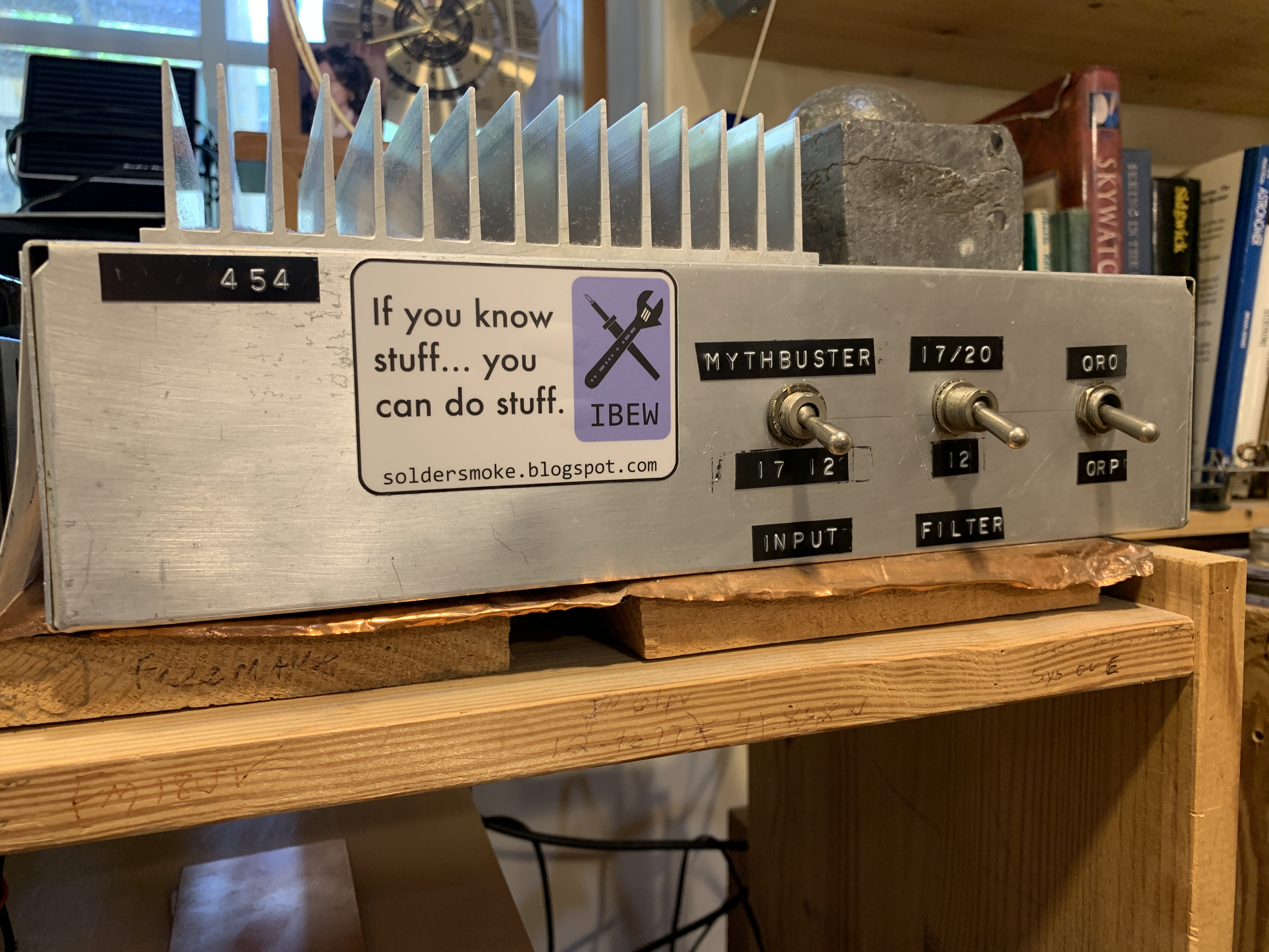
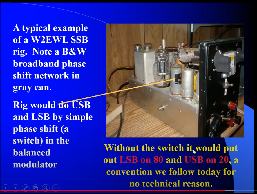
I got started with band switching with my Mythbuster rig: I would get 75 and 20 meters. The IF was midway between the two at 5.2 MHz. My VFO (from an old Yaesu FT-101) ran around 9 MHz. Boom, it worked, with the added benefit of receiving and transmitting LSB on 75 and USB on 20 with no switching of the BFO/Carrier Oscillator.
Then I did 17 and 12 meters. Kind of a WARC-band special. IF was at 21.4 Mhz. VFO ran around 3.5 MHz. So by adding the incoming modulated signal 18 MHz signal and the VFO, you get to 17 meters. By subtracting the VFO from the incoming 24.9 MHz signal you get to 12 meters. And both are on USB (apply the Hallas rule), so again, no switching of BFO/Carrier frequencies are required.
Finally, at solar max, I built rigs for 15 and 10. Here the IF was 25 MHz. Again the VFO was around 3.5 MHz. Adding the incoming 21 Mhz signal to the VFO gets you to 25 MHz, subtraction of the VFO frequency from the in coming 28 MHz signal takes you to 25 Mhz and thus 10 meters. Again, no sideband inversion (Hallas rule). Both signals are USB and stay on USB. (I built two versions of this rig -- one stays in Virginia, the other is heading to the Dominican Republic.)
In the ARRL book QRP Classics, there is an article from the 1990 Handbook entitled "A Band-Imaging CW Receiver for 10 and 18 MHz." The article may have been based on a receiver built by Dave Newkirk AK7M (Rod Newkirk's son). Unfortunately in the write-up for the ARRL handbook, the drafters repeat the oft-repeated myth about how 9 MHz IF and a 5.2 MHz VFO would supposedly produce LSB on 75 and USB on 20. This just doesn't work. But if you put the IF at 5.2 MHz and the VFO at 9 MHz, it does work, as demonstrated by my Mythbuster rig.


.jpg)


