Podcasting since 2005! Listen to Latest SolderSmoke

Showing posts with label VFO. Show all posts

Sunday, May 8, 2022

The JF3HZB Digital VFO Dial in the DJ7OO Direct Conversion Receiver (Who is JF3HZB?)


Pete was talking about this beautiful Digital VFO dial in the latest podcast.  In response, Klaus sent me an e-mail with links and the video above,  describing how he used the VFO dial in a very cool Direct Conversion receiver project.  TRGHS. 

Here is the web site (you can easily get the English translation by clicking on the UK flag link): 
http://www.kh-gps.de/uni-rx.htm

Thank you Klaus!  And thanks to JF3HZB!  (Does anyone have more information on him?) 

Wednesday, April 13, 2022

The 17 & 12 SSB Transceiver -- Circuit and Build Info -- Video #4


I REALLY LIKE THIS RIG. IT IS LIKE A MAGIC CARPET THAT CARRIES MY VOICE ACROSS THE SEAS.

Cutting Display Hole sets off smoke alarm. Reverse Polarity Protection. IF and Crystal Filter at 21.470 MHz 50 ohms! TRGHS! Amp for VXO Carrier Oscillator/BFO. Mic Amp from uBITX. Transmit/Receive switching from mic connector. VFO: NO DIE CAST BOXES! HT-37 Variable Cap, Frequency Shift. BP filters from QRP LABS designs (G0UPL). TIA amp boards from K7TFC. Needed RF amp to hear band noise. BITX40 PA design, but RD006HHF1 instead of IRF510. Should I run receiver input through LP filter? Frequency Readout Story: How to use one San Jian counter on two bands.

Friday, April 1, 2022

SolderSmoke Podcast #236 -- Bill's 17-12 Rig, Pea Shooter, VFO Wisdom, Temp Compensation, Need Code for Max2870, Making Enclosures, MAILBAG

ARC-5 R-23 Nav Receiver Parts

SolderSmoke Podcast #236 is available!

http://soldersmoke.com/soldersmoke236.mp3

Winterfest!  Many Boatanchors.  Lots of old good analog test gear.  Talk with Dean KK4DAS.  Met up with Armand WA1UQO and Charles AI4OT. 

Pete's Bench: 

-- Looking for help in software development for MAX2870 board.  
-- Tapped Capacitance Impedance Matching
-- The Pea Shooter (See N2USD's version in videos
 below).
-- Tribal Knowledge on Making Enclosures

Bill's Bench: 

-- 17-12 Band Imaging SSB Transceiver.  It works on both bands. 
-- Plan for Glowing Numerals (N6QW has been there and done that!)
-- WU2D's videos on VFOs.  
-- Temperature Compensation:  HT-37 capacitor.  FT-101 VFO,  even in the ARC-5 receiver! 
-- Trying to get more rigorous about receiver design.  Gain distribution, IMD, Dynamic Range, etc. 
-- Do I need a true RMS audio voltmeter?  Or can I get the same info from freeware audio spectrum analyzer and soundcard?
-- 6EA8s replace 6U8s in MMRX 

SHAMELESS COMMERCE DIVISION:   We have a sponsor!  

PARTS CANDY out of Chicago produces quality test leads for your bench.  The guy who runs the company is Carlos, and he is one of us.  He is an electronic tinkerer. See the ad on the left hand column of the SolderSmoke blog.  Just click on the picture of the test leads and you will be taken to Carlos's ebay store.  Go for it. 

Mailbag

Walter KA4KXX in Orlando -- Diodes in BITX Bilats -- Why?  Farhan says To prevent reverse junction of off transistor from conducting and clipping waveform. 
Tony G4WIF -- Audio test gear and G3ROO paraset
Todd K7TFC Pine boards, TIAs and 12 meters
Dean KK4DAS  Ceramic Variable Oscillators on 40.   Juliano Criteria? 
Mike WU2D   VFOs and Temp compensation. ARC-5s
Chris KD4PBJ   A really nice parts care package -- Thanks Chris! 
Steve M0ECS.  Inspired by SS, moved something off the Shelf or Box of Shame. 
Jason KD2RKN Building a DC receiver.  It is all our fault. 
Chris Mannon in Indiana joining the CBLA
KC4GMH is listening! 
Ed N2XDD has been armed with a 3.579 MHz crystal.  
Harvey Wa3EIB working on his museum 
Tim AG4RZ is BACK IN THE SOLDERSMOKE! 
Fred KC5RT -- an old friend -- recommends Bangood RF sig gen for 88 bucks. 
Shlomo 4X4LF listening and homebrewing from a Kibbutz in Israel. 
Chuck KF8TI was a Peace Corps Volunteer in the Philippines. 


Sunday, March 20, 2022

17 - 12 Dual Band SSB Transceiver On-The-Air


It is still completely al-fresco, with all the guts exposed, but I got it on the air this morning.  I was 17, running it through my CCI  .1kW  100 watt amp to a tuned doublet.   Four QSOs so far: HP3SAM, K5BM, N4ZUL, and II3WRTC.   

The structure of the rig is basically BITX. 

The blue boards you see are TIA boards developed by Todd K7TFC. 

No major problems to report.   I will try it out on 12 meters  soon.  The receiver was working well on that band. 

Monday, March 14, 2022

Wednesday, March 9, 2022

Video #2 17/12 SSB Transceiver -- Receive RF Amplifier Needed?


Lots of progress to report on the 1712 rig. 

With just two TIA amps (one on either side of the 10 pole filter) and the AF amplifiers, I now have it inhaling on 17 meters.  But nothing heard so-far on 12. On both bands I can hear the band noise, but just barely.  So I may try some RF amplification ahead of the mixer. What do you guys think about this? I think the two TIAs and the crystal filter are providing 30 db of gain.  

I want to get the receiver circuitry working well on both bands before I build the T/R and transmit amplifier circuitry.
  
It is nice to have a project on the bench!  

I am trying to find a shaft extender or adapter for that big beautiful HT-37 main tuning cap.  The shaft on the capacitor has a width of 1 cm or 0.393701 inches.  I need something that will grab onto that and allow for the connection of a tuning knob.  Please search your junk boxes!  

Friday, February 25, 2022

Split Stator Temperature Compensation Also Used in Yaesu FT-101


The eagle eye of VE3EAC spotted this (he also correctly pointed to a tiny broken "tine" as the cause of my  HP8640B woes).   I had missed the temp comp circuit.  Inside the Yaesu FT-101 VFO box that I used in my Mythbuster rig, there is a split stator capacitor and two temperature compensation caps similar to that recently described by Mike WU2D.  Very cool.  You can see the temp compensation cap in the picture (above). The red arrow points to the split stator cap,  the blue arrow points to to the two temperature compensation caps attached to it. You can see them all in the schematic below(in the lower left of the schematic). 

Thursday, February 24, 2022

Old Military Radios at the Air and Space Museum Udvar-Hazy Center, and Autogyros

 
My son Bill and I were out at the National Air and Space Museum's Udvar-Hazy Center (out near Dulles Airport, where they display the really big stuff).  We spotted these old military radios.  The ARC-5 Command sets caught my eye.  Of course I was thinking about the great VFO parts inside those boxes...   The acknowledgement of the ARC-5's contribution to ham radio (on the card) was nice. 

 They also have an ART-13 on display.  


We had a lot of fun looking at all the planes.  We were especially impressed by the Autogyros. 
The Bensen B-6 Gyroglider seemed to be really pushing the envelope (of good sense!).   This was a an Autogyro with NO MOTOR.  It was towed!  No license required as long as you didn't release the tow line.   Note that it was designed in 1954 to introduce teenagers "to the thrills of flight at minimal cost." The headgear and goggles were key.  And the kit was only $100! 


Wednesday, February 23, 2022

An Analog LC VFO for my 17/12 Meter SSB Transceiver (VIDEO #1)


Here's my initial work on a VFO for my 17 meter -- 12 Meter Single Conversion Dual Band SSB Transceiver. The IF (crystal filter) will be at 21.4772 MHz. On 12 meters the VFO will run from 3.5128 to 3.4528 MHz. On 17 the VFO will run from 3.3092 to 3.3672 MHz.

The transistor I am using is an SK3050 Dual Gate MOSFET. I bought a bunch of these years ago in a panic when I heard that 40673's were getting scarce.

I forgot to mention another important reference: Joe Carr's Popular Electronics VFO articles:

Thanks again to Dale K9NN for the bags of NP0 capacitors. And to Pete N6QW for the suggestion on the HT-37 main tuning cap.   Thanks to Mike WU2D for the great VFO videos, and to Frank Harris for his wonderful book on homebrewing.  And we can't forget the great reference books that guide so many of our projects: Solid State Design for the Radio Amateur and Experimental Methods in RF Design -- thanks to Wes Hayward W7ZOI and all of his co-authors.  

Saturday, February 19, 2022

Pete's Eclectic Approach to the Pea Shooter, San Jian counters on Analog VFOs, Non-Restaurant Menus

I liked Pete's comments on the various (analog, digital, mixed) approaches to homebrew: 

http://n6qw.blogspot.com/2022/02/2022-return-to-peashooter-build.html

http://n6qw.blogspot.com/2022/02/2022-peashooter-20m-compact-ssb.html

I too have San Jian digital counters watching the stability of analog VFOs (DX-100, HQ-100, Mythbuster). 

Variety is the spice of life!  

I also liked Pete's comment about the fellow who does on-the-air menu counseling for FTDX-3000 owners.  I sometimes run into guys on the air who want to do something similar with my simple homebrew rigs.  They start by making comments about my audio -- they will usually say it is "too high" or something like that.  Especially when I'm using the separate transmitter and receiver (which have to be "netted" imprecisely by ear), I have to explain that maybe resort to their RIT control would help.  If they persist, I sometimes have to tell them that how my rig sounds depends A LOT on the placement of the carrier oscillator relative to the passband of the crystal filter (most recently, the filter from the 1963 Swan 240).  Most of them have never had to do that kind of adjustment, so the "technical discussion" usually ends at that point, with my interlocutor saying 73, and presumably moving on to someone whose rig has menus to fiddle with.  (Recently heard audio techno term: "massaging the codec.") 

To each his own!    


Tuesday, February 15, 2022

Differential Temperature Compensation Capacitors in the Hallicrafters HT-37 Main VFO Tuning Circuit

 
I've been watching with great interest Mike WU2D's excellent series on VFO construction.  His second video is especially interesting because he talks about how we can use a split stator differential capacitor to build a temperature compensation circuit that will allow us to "dial in" the proper amount of temperature compensation.  

The heart of this circuit is the split stator differential capacitor.  The stator is split; but there is a common rotator. As the rotator moves, the capacity across one part of the capacitor increases while the other part decreases -- thus the total capacity remains unchanged.  If we connect two capacitors of the same capacitance BUT OF OPPOSITE TEMPERATURE CHARACTERISTICS -- we can use this split stator cap to select just the right amount of temperature compensation.   Very cool.  Even cooler:  Mike actually built a split stator differential capacitor.  That, my friends, is dedication. 

I was sitting here this morning thinking about all this when it occurred to me that right in front of me was a capacitor that might be relevant to all this (see above).  I bought it on e-bay one year ago after Pete N6QW had alerted me to it.  It is the main tuning capacitor from an HT-37 transmitter.  What attracted us was the big anti-backlash mechanism.  But now I realized that it had another charming feature.  

Looking at it a bit more closely I saw a split stator differential cap just like the one that Mike had made.  Attached to the two rotors were two tubular capacitors.  The three caps are in parallel with the main tuning cap.  Bingo -- this is a temp compensation circuit.  

I checked the HT-37 manual.  The manual says that temp compensation is set at the factory.  OK.  But the schematic does not show the split stator caps and the two tubular caps (see below).  Could it have been that this circuit was added later perhaps to address drift? (We do see it in the HT-32B schematic -- see below.)

HT-37 VFO SCHEMATIC

Anyway, it was very cool to find this example of the circuit Mike was discussing.  In the photo at the beginning of this post you can see the three caps.  Below you can see the split stator cap in the background. 


In the comments a reader points out correctly that this circuit was discussed in the ARRL book "Single Sideband for the Radio Amateur."  Indeed, it is on page 51 of the 1970 edition, ARRL  gave credit for the circuit to Hallicrafters: 


HT-32B VFO Circuit

Joe Carr K4IPV (SK) also discussed this circuit.  In his article in Popular Electronics in August 1993, he too gave credit to Hallicrafters.  Carr also gave some detailed instructions on how to use the circuit to stabilize a VFO.  See pages 78 and  79 of the August 1993 Poptronics: 

Friday, February 4, 2022

Mike WU2D -- VFO Video #3


Mike WU2D continues to show us how it is done.  I hope to make all my future VFOs using the techniques he describes.  Thanks Mike. 

Tuesday, February 1, 2022

Mike WU2D Shows Us How to Do Temperature Compensation in Homebrew LC Analog VFOs


In several of the articles that I have seen about the homebrewing of VFOs the authors seem to throw up their hands when the subject of temperature compensation comes up.   They seem to just say, "This is hard.  Not for the faint of heart.  Good luck with that!"   But in this great video Mike WU2D shows us in very practical terms how to do temperature compensation of VFOs.   This is really great news for those of us who prefer old style coils and caps to Si5351 chips.  Thanks Mike!  

Thursday, January 20, 2022

Mike WU2D on VFOs (with additional Tribal Knowledge from Frank Harris K0IYE)


Great stuff from Mike and from Frank Harris K0IYE.   But when I put the VFO in a box, I usually try to put the frequency determining components (the coil and most of the caps) in the box, with the powered components (transistor, Zener,  voltage dropping resistors) outside the box.  If I put these powered components in the box, I find there is some drift as these components slowly heat up the interior of the box. 

Dean KK4DAS and he VWS Builders have just stated building analog VFOs, so Mike's video is very timely for them. 


Wednesday, October 13, 2021

SolderSmoke Podcast #233: PIMP, Boatanchors, Novices, MMM, Heathkits, DC Receivers, Mailbag


SolderSmoke Podcast #233 is available. 

http://soldersmoke.com/soldersmoke233.mp3

Travelogue: Cape Cod. SST. Marconi Site.

The WFSRA:   The World Friendship Society of Radio Amateurs.


Pete's Bench:

The Pimp.
The NCX rig.
The Collins.
The many DC receivers built worldwide.
The parts shortages are real! Several key radios on hold. Si5351 sub.
Talk to G-QRP convention

Bill's Bench:

FT-8. Not for me. I tried it.
Novice Station Rebuild.
Globe V-10 VFO Deluxe.
Selenium rectifier removal CONTROVERSY?
Not crazy about my Novice station. Not crazy about CW. 
Mate for the Mighty Midget. Again. 
Mike W6MAB -- Detector problems LTSPICE Check
One more mod for MMM RX. Ceramic filter at 455.
Dropped screw inside tubular cap on Millen 61455 transformer. 
Talk to the Vienna Wireless Society
Thinking of a Moxon or a Hex beam.


BOOK REVIEW Chuck Penson WA7ZZE New Heathkit Book. http://wa7zze.com


Mailbag

-- New SPRAT is out! Hooray!
-- Todd K7TFC sent me copy of Shopcraft as Soulcraft. FB.
-- Dean KK4DAS building an EI9GQ 16 W amp. FB.
-- Jack NG2E Getting close on Pete's DC receiver.
-- JF1OZL's website is BACK!
-- Tony K3DY sent link to cool books. 
-- Sheldon VK2XZS thinking of building a phasing receiver.
-- Peter VK2EMU has joined the WFSRA. FB!
-- Ned KH7JJ from Honolulu spotted the Sideband Myth in the AWA video.
-- Chris M0LGX looking at the ET-2, asks about the variometer.
-- Pete Eaton Nov 64 anti HB rant in november 1964 QST. Wow.
-- Josh Lambert Hurley spreading FMLA stickers in the UK. FB
-- Stephen VE6STA getting ready to melt solder.
-- Got a great picture of Rogier PA1ZZ back on Bonaire.
-- Farhan reading the manual of Hans's new digital rig.
-- Paul G0OER wonders if FMLA getting ready to move on 5 meters.

Saturday, October 2, 2021

Selenium RECTIFIED

Selenium rectifiers. The name kind of sounds like Dilithium crystals, possibly related to flux capacitors. 

Anyway, there were two of them in the Globe Electronics V-10 VFO Deluxe that I recently bought.  Obviously they had to go, so I took them out yesterday, replacing them with a 1N5408 silicon rectifier.  

The new diode had a significantly lower voltage drop than the selenium rectifiers -- this pushed the output voltage from the power supply up to around 200V.  It is supposed to be around 185 V.  So I put a 470 ohm,  5 watt resistor (found in the junkbox) in series.   This brought the output voltage to 167 V.  Close enough.  VFO seems to be working fine.  

I'm glad I did the extraction before these aging components released their nasty toxic smoke. 

W3HWJ has a good article on replacing these nasty old parts, with some interesting info on their history:   http://www.w3hwj.com/index_files/RBSelenium2.pdf

Backgound on the element Selenium:  https://en.wikipedia.org/wiki/Selenium


Wednesday, September 29, 2021

N2CQR (WN2QHL) Novice Station Re-Created

 
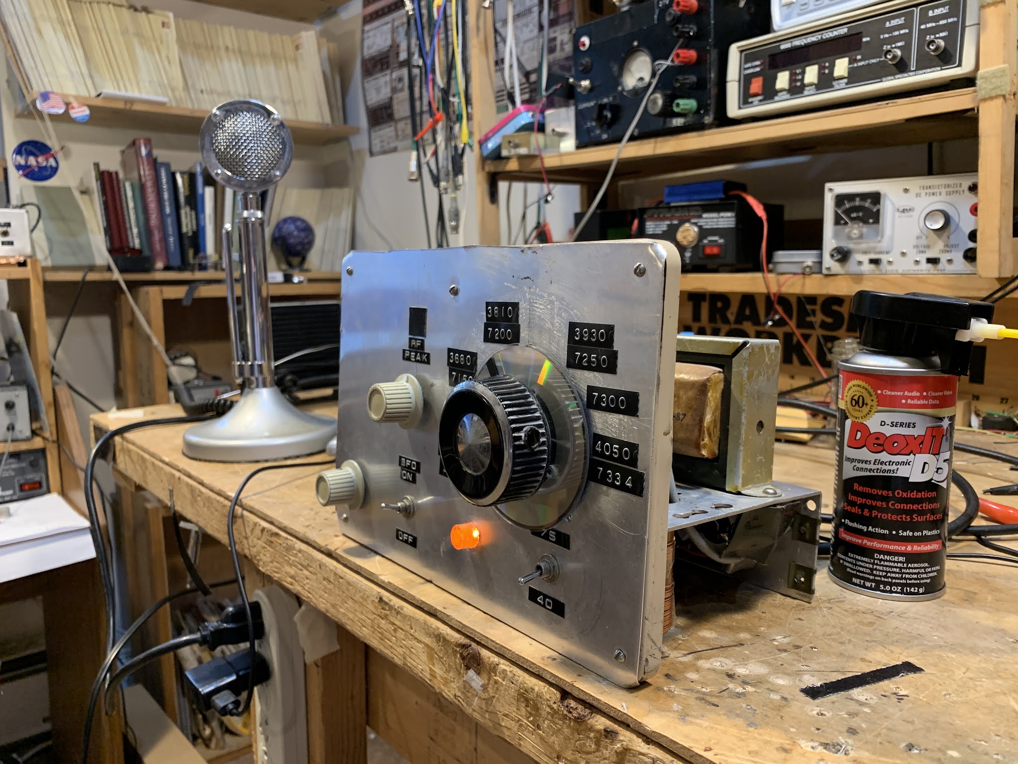
There it is.  The 2021 re-creation of the WN2QHL Novice Amateur Radio Station.  This is what I had when I first went on the air in April 1973 from Congers, NY. 

-- I got my first Lafayette receiver (WITH JEWELED MOVEMENTS!) for Christmas in 1972.  My mom drove all the way into New Jersey to get it for me. 

-- I bought my first DX-40 and the Globe VFO Deluxe from someone in the Crystal Radio Club.

For this re-creation station: 

-- I got this recently acquired Lafayette free-for-pickup from a very kind SWL in the Shenandoah valley.  (I've discussed this receiver extensively here.) 

-- The DX-40 is the result of a couple of junkers that I bought in a hamfest some 23 or 24 years ago.  It might have been the Timonium Hamfest.  I cannabalized one of them and made one good DX-40 out of the two.  Parts of the cannabalized unit carry on the good fight as pieces of my balanced  antenna tuner (the coils were useful there) and as the chassis for my first SSB transmitter. 

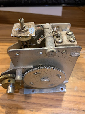
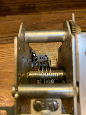
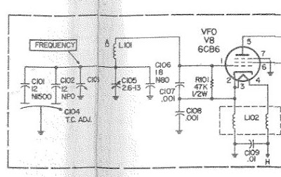
-- The Globe VFO Deluxe was harder to recover.  There are just not a lot of these things around.  I actually put up a plea for one of these on the SolderSmoke blog.  Not even the IBEW could come up with one of these things.  But then, last week on Facebook I came across a fellow who was selling one.  Deal!  Check our the nice Juliano Blue light indicating 40 meter operation. 

Putting these three devices together was more challenging than I thought.  To get them to work together decently three different things had to happen as the result of throwing one switch: 

1) Antenna had to switch from receiver to transmitter. 
2) Receiver had to be largely muted (leaving some key-down signal for sidetone).  
3) VFO had to be turned on (I left it running and just keyed the DX-40).  

Fortunately I have almost 50 years more experience than I did when I first set this station up.  So I was able to do this better in 2020 than I did in 1973.   I had a 3PDT relay that I had built for a DX-60 station.  I was able to use it to do all three things described above. 

Muting the Lafayette was a bit tricky.  On the back octal connector they have two post  (1 and 3) that are normally connected.  Disconnecting 1 from 3 completely mutes the receiver by cutting off a needed ground connection to the RF amplifier and to an IF amplifier.  The Lafayette manual tells you to connect these terminals to the "muting voltage" presented by your transmitter.  The DX-40 doesn't have such a voltage, and I was reluctant to connect any voltage to this terminal for fear of blowing up the RF and IF amplifiers.  I figured that just putting a big resistor across 1 and 3 would mostly mute the receiver.  The 3PDT relay shorts this resistor on receive, un-muting the receiver. I use a 500,000 ohm resistor.  It works well, but the sidetone is chirpy while the actual signal is not.  This is a bit annoying. 

I re-capped the DX-40 when I got it back in the late 90's.  Those caps are still good. 

The Globe VFO had also been recapped.  But it still has selenium rectifiers in there.  I will change them ASAP.  Also, the Globe VFO had a somewhat mysterious second transformer in there.  I wondered what that was.  I measured the output:  6.3 V.  That is a filament transformer.  My guess is that the filament winding in the main transformer went open, maybe as a tube failed. Instead of replacing the whole transformer, they just popped in a replacement filament transformer.  That's fine. 

I've been on the air with this rig, mostly on 40, as I was as a Novice.   I can work anyone I hear on 40 meter CW and my CQ's are heard in Europe (as shown by the RBN). 

I'm struck by how physically BIG these pieces of gear are.  Much bigger than our beloved BITXs. 

Regarding T/R switching:   There was a line in the 1973 ARRL Radio Amateurs Handbook that really got to me back in 1973:  Page 640, in the chapter entitled "Assembling A Station:" "

"In any amateur station worthy of the name, it should be necessary to throw no more than one switch to go from the 'receive' to the 'transmit' condition." 

By this standard, my station was probably unworthy of the name.  I don't remember how I handled T/R changeover, VFO keying, receiver muting and sidetone,  but it almost certainly involved throwing more than one switch.  But now, I am happy to report, my novice station is finally up to the ARRL's high standards.  As Pete says, "When you know stuff you can do stuff." 

Saturday, July 17, 2021

Mythbuster Video #7: Bandswitch, Reverse Polarity Protection, CW with Clarifier Offset

I have the speaker mounted on the front of the board. I kind of like it like that. I now have a bandswitch, and reverse polarity protection (no more living dangerously for me). That Yaesu VFO clarifier circuit might prove useful should I decide to give this rig CW capability. I once again find myself thinking that I might never put this in a metal box. Frank Jones had the right idea.

Wednesday, July 14, 2021

Mythbuster Video #4 -- First Signals, 75 meter Bandpass Filter, Yaesu VFO output


This receiver required almost no coaxing or tweaking, probably because I had been so careful about testing and measuring each of the stages. 

I have been pleasantly surprised at how well the receiver works without an RF amplifier ahead of the first mixer.  But I need to know how much AF gain I have in order to understand how/why the entire receiver works so well.  I think I have about 35 db of gain (combined) through the two TIAs and the crystal filter.  That would mean that all of the remaining gain is provided by the AF amplifiers (with some loss in the product detector).   I haven't really measured the gain of the AF preamp/LM386 combo, and I had some trouble measuring the input impedance of the pre-amp with the NanoVNA.    

The 75 meter LC filter to the left of the VFO is actually a bandpass filter, not the lowpass filter. And what I call "the mixer" to the right of the VFO is really the Product Detector/BFO.

For the 75 meter bandpass filter, I used the ELSIE program. 

75 meter Bandpass Filter designed in Elsie.  10 turns on a T50-2 toroid yield .46uH.

Here's the plot from Elsie on the 75 meter BP filter.  

Alan W2AEW asked for a picture of the VFO output. 
On this shot I had the probe between theVFO and the 
outboard booster amp that I built to bring it to 7dbm. 

Tuesday, July 13, 2021

Mythbuster Video #3 -- Using the VFO from a Yaesu FT-101


FT-101 VFO

I used LTSpice and Wes's FBA program (from LADPAC) to come up with a circuit that would provide the needed gain. I needed to get the 290 mV rms signal (across a 50 0hm load) up to the 500 mV rms signal needed by the ADE1 mixer.  Above is the amplifier that I came up with.  The key here is to adjust R2 and R1 to get the required gain. 
Designer: Douglas Bowman | Dimodifikasi oleh Abdul Munir Original Posting Rounders 3 Column