Podcasting since 2005! Listen to Latest SolderSmoke

Showing posts with label troubleshooting. Show all posts

Sunday, September 13, 2020

HP8640B -- Fault Found! A very TINY and Hard-to-Fix Fault


I've been troubleshooting the internal counter in my HP8640B signal generator. The generator itself works fine.  And the counter works fine for all signals coming in on its "external" port.  But the internal counter stopped working properly above 16 MHz. So I started digging into the manuals and the schematics, re-familiarizing myself with the digital logic behind pre-microcontroller  frequency counters.  NOTE:  If you are working on one of these, be sure to be using the correct version of the manual and schematic. At one point I found a really nice high def copy of an HP8640B manual (for one used in a Patriot Missile System!) only to discover that MY A8A3 board was significantly different from the one in this manual.  BAMA provided a manual that matched my device:  http://bama.edebris.com/manuals/hp/8640b/

Every dark cloud has a silver lining.   Here, the silver for me came from opening up the HP8640B.  What an impressive looking piece of gear.  It looks like something from the Apollo command module, or perhaps from a nuclear weapon.  "The RF source is a 256 to 512 MHz cavity-tuned oscillator that is mechanically tuned..."  There is phase lock circuitry.  The are AM and FM modulators and a really useful array of attenuators.  There is a frequency counter with an external port and an internal frequency counter that measures the original 256-512 MHz signal, then divides down to give a very accurate readout of the output frequency.    This is the kind of device that would generate a cult following.  Count me in! 

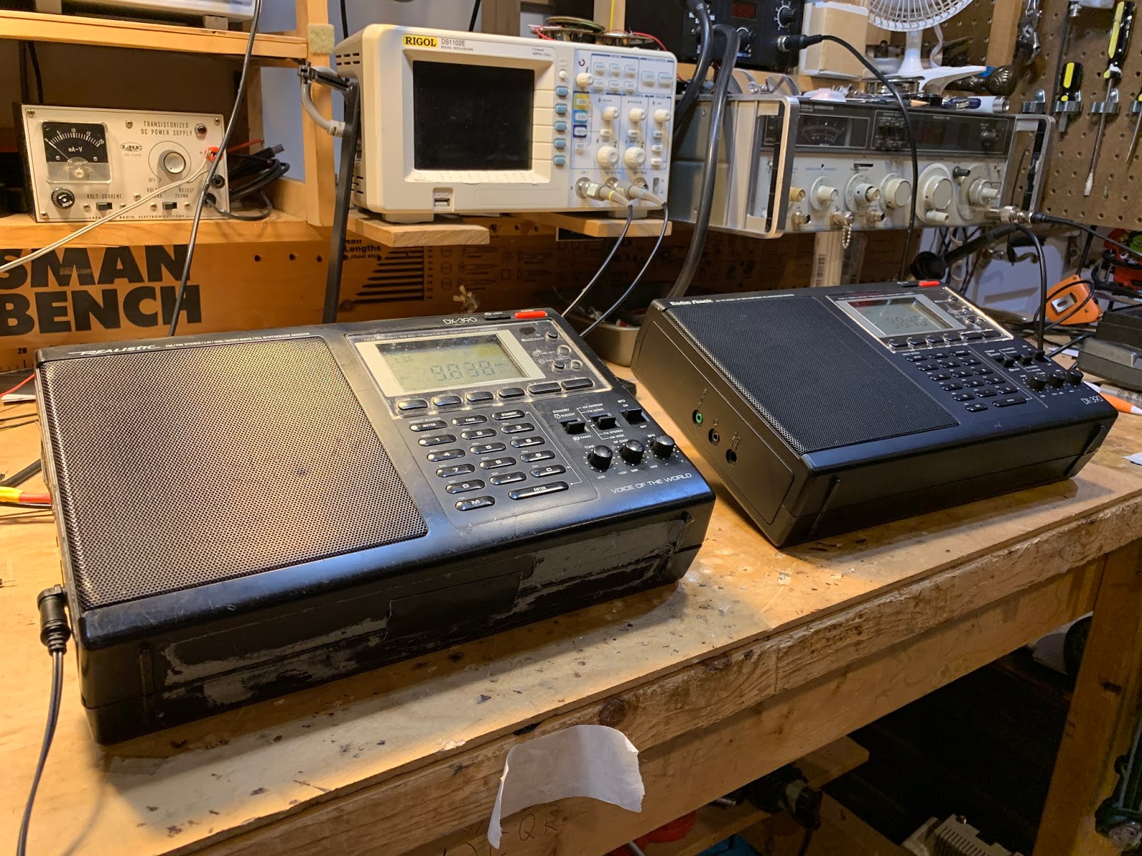
Also,  I've sometimes lamented the lack of VHF test gear on my work bench -- the HP8640B could really help me move me into the VHF range.

I started the troubleshooting with some observations and noodling. At what frequency did the internal counter stop working?  What did the readout look like when it stopped working?  What device failure could lead to these symptoms?  I was aided in this by suggestions sent in by readers of my previous blog posts.  Thanks guys.  

I was just getting ready to start some intrusive testing on the logic devices in the internal counter when Dave VE3EAC sent me this: 

-----------------
I think you might be overthinking the failure mode here. I had a similar problem with my unit and it was one of my early Covid-fix-it projects. There is an assembly that controls the bands on the front. It has the famous gears that crack. On the back side are two sets of rotary switches that control a lot of stuff. The switches are of a very unique HP design and offer a lot of advantages over traditional switches EXCEPT they fail in an unusual manner. A PC board has all of the interesting wiring and very tiny double leaf springs short tracks together as needed. The springs tend to break away from the plastic posts on the rotating plate and not make the needed contact. Very carefully examine the insides of the 8640 and your bench top to see if any have fallen out. These are difficult to buy or fabricate. The disk is designed to be rotated 180 and use a new set of posts to locate the springs. Use a small dab of epoxy to set in place. The totally mechanical repair fixed my unit that also would not read above 16 MHz. There are a number of web pages that give great detail of this repair. Also it is worth while to replace the Delrin gears if they are cracked. Replacement brass ones are available on eBay and they will permanently fix the gear problem.
---------------

I had thought about the problem being in the frequency range switch, but I had sort of tested for this by slowly rocking the switch through various positions as I watched the display.  A dirty rotary switch will usually allow the circuit to intermittently work as you rock the switch.  But this didn't happen.  And the HP switch felt quite sturdy, so I focused on the circuitry.  

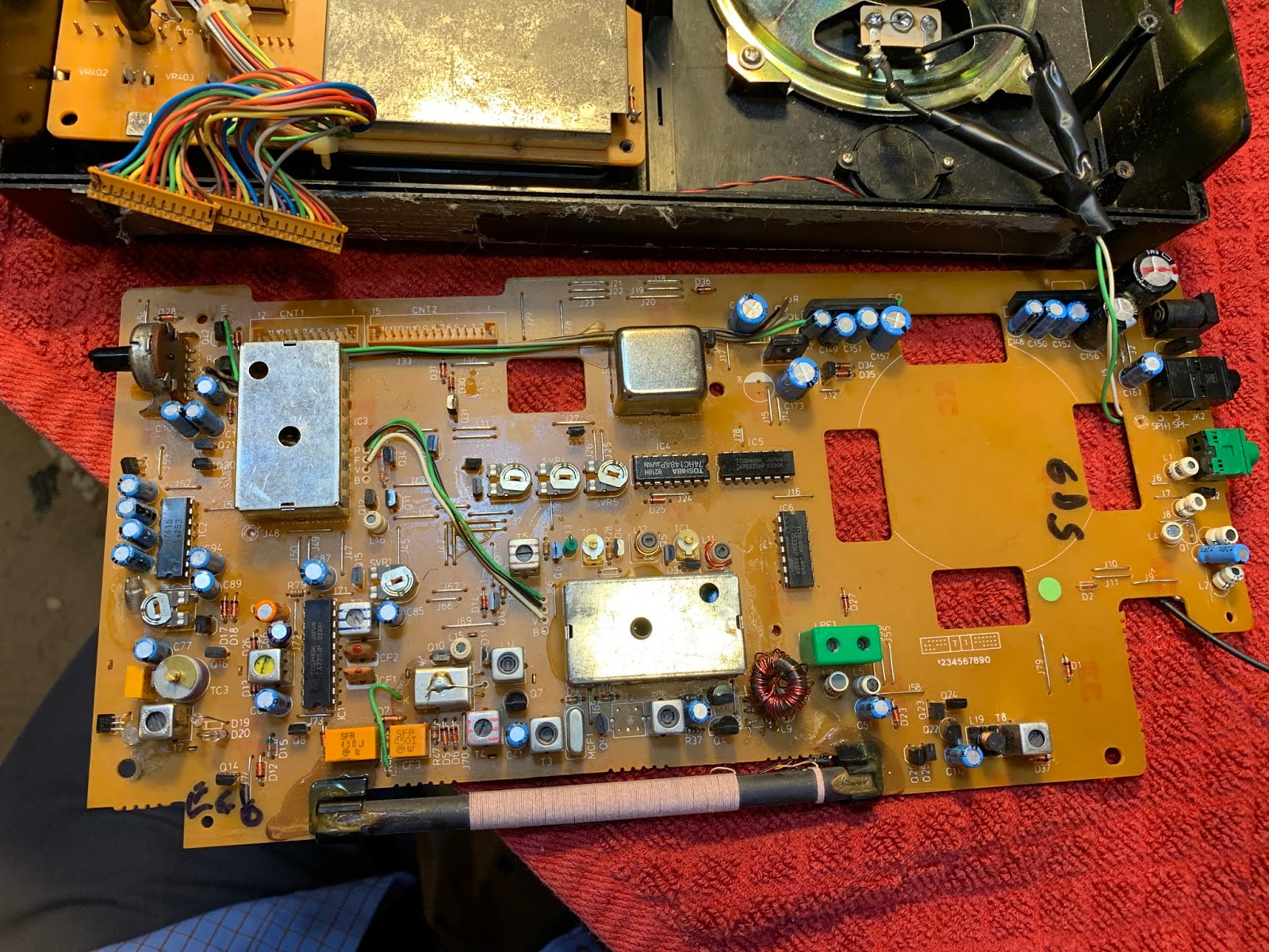
When I got VE3EAC's message, I carefully flipped the HP8640B over and for the first time opened the bottom of the compartment.  The bottom view is much more impressive than the top view: 


The switches that VE3EAC wrote about  are just below the ribbon cable near the center front. I could see the little springs that he was discussing on the switches.  They appear MUCH more delicate than the rotator on a standard rotary switch.  And I didn't see any of them lying around below the switch.  But when I tried to flip the HP8640B over, something in there moved and caught my eye.  I pulled out some tweezers and pulled this out: 


Wow.  That little spring contact fell off the switch.  That was preventing the HP8640B internal counter's time base from changing as I went above 16 MHz.   It is ironic that such a big and solidly built device such as the HP8640B should be laid low by such a TINY part.  

This gets me back to my original question:  Discretion or valor?  Getting that spring back onto that switch will not be easy.  VE3EAC sent me this K6JCA link describing how to do this.  Yikes, it even requires the purchase of a special tool!  

I'm going to let the HP8640B sit there with the cover off for a while.  It will be taunting me, challenging me to fix it, to make it work the way Hewlett and Packard intended.  It may take a while, but I think I'm going to have to accept this challenge. I've become  real fan of the HP8640B and it would be a shame to leave it wounded like this. 

Thursday, September 10, 2020

The Agony of Troubleshooting -- From China


I am troubleshooting my beloved NYC HP8640B Signal Generator (thanks to Steve Silverman and Dave Bamford).  Some of you may wonder why I don't just replace this beast with something small, lighter, cheaper and newer.  Well, I have not found any new sig generators that will do what this beast does:   It goes all the way up to 256 MHz (higher with an extension kit).  It has a great attenuator in it so you can set the output just where you want it.  AM or FM modulation.  Really useful.  So I think I'll fix it. 

My problem is that the internal freq counter stops working above 16 MHz. Using the very extensive  documentation, and without even really opening up the machine, I think I have located the fault.  I think it is in the Counter Time Base Assembly board A8A3.   Now of course, the fun begins.  (Tips, advice, solutions, and words of encouragement would all be appreciated.) 

While planning my assault on A8A3, I came across the web site of BH1RBG.  He too has recently been working on an HP8640B.  His problem was different, but when I read through his site I saw evidence that the agony of troubleshooting is something that is the same all around the world.  Check out his description of the agony: 

I even suspected the LM723 should had something bootstrapping circuit, make sure the Q4 sure start. Because the external reference VR3 is floating too, oh, my godness.

I became hopeless, and ordered several LM732,and waiting delivery for days. This beast frustrate me so deeply, changed the LM723 does not help anything. And i almost desoldering everything in the board!

Oh man, I've been there. Several times while in the throes of a troubleshooting battle I have actually had dreams of removing all the parts from a troublesome PC board.

BH1RBG has a very interesting site with lots of ham radio projects: 

https://sites.google.com/site/linuxdigitallab/rf-ham-radio?authuser=0


Sunday, September 6, 2020

Marc Verdiell Has The Knack


Here is Marc Verdiell, the "Curious Marc" who repaired the Soyuz Clock (shown in yesterday's blog post).  

Really cool.  Many SolderSmoke fans will completely understand Marc and his passion for 
electronics. 

Saturday, September 5, 2020

Taming Glitches in a Soyuz Space Clock (Plus -- Inside a Logic Chip and How Crystals Work)


Thanks to Bob KD4EBM for sending this.  

There is so much good info in this video:  They crack open a logic chip and look at the internal construction (it is entirely understandable by mortal minds).  They use cool test gear to troubleshoot the clock from a Soyuz spacecraft.  They explain very clearly the series and parallel resonances of quartz crystals, then display these resonances on a very nice spectrum analyzer.

The creator of the video is CuriousMarc.  He has many other interesting projects: 

https://www.youtube.com/c/CuriousMarc/featured

https://www.curiousmarc.com/ 

His bio is here: 

One paragraph from his bio really resonated with me: 

Working on this old stuff forces me to deal with the very fundamentals of electronics (and electro-mechanics). The principles are exactly the same as today, but nothing is hidden in mysterious circuits - you can understand and fix everything. Years of Moore's law has sure given us gobs of transistors, oceans of memory and a glut of gigacycles, but many times, particularly in consumer hardware, these are simply used to cover up poor and inefficient designs - and resource devouring software. What Intel giveth, Microsoft taketh away, as they say. It often irritates me that my PC takes several seconds to react to a simple command, in which time it must have executed billions of unnecessary instructions and consumed a few gigabytes of memory, no one knowing exactly what for anymore. Nothing like this in old high-end hardware: designs are pure and efficient, and the lack of resources is compensated by engineering mastery and immense cleverness, which is a joy to reverse engineer. Not only does it teach us timeless electrical fundamentals and engineering tricks, but it also gives us a much better appreciation of today's tech. How did all the technology we take for granted came to be? It will make you a far better engineer and inventor if you take the time to be a thorough student of the inventions of your illustrious predecessors.

Tuesday, August 25, 2020

Great Video on PC Board Techniques, with a Focus on Surface Mount


Wow, lots of wisdom in this video from Leo Fernekes.  Great hints and kinks on prototyping with copper clad boards. I need a Dremel just so that I can make Leo's board cutter.  And I can see that I need some of that liquid flux and isopropyl alcohol. Surf boards and headers! Who knew?  Teflon coating for the wires -- gotta get it. Glad to see that Leo is also a fan of copper tape.

His emphasis on the importance of stage-by-stage construction and testing is right on the mark.  

My only disagreement with Leo is about his use of steel wool.  I've found that steel wool will inevitably cause little tiny "Murphy Whiskers" to float around your workbench. They will eventually settle onto the most inconvenient and damaging place on your board.  So I have banished steel wool from my workshop.  Those green, non-metallic Scotch Brite pads work just as well and don't cause shorts. 

Three cheers for Leo. He is based in Thailand.  He has an interesting background and some really amazing projects and insights:  

http://www.luminati.aero/leofernekes

http://www.fernekes.com/blog/

https://www.youtube.com/channel/UCe1bjEcBichpiAMhExh0NiQ/videos

Thanks to Tore LB4RG for alerting us to Leo's video.  

Sunday, August 23, 2020

Mike WU2D's Great Drake TR-3 Refurb Video -- Part 2


Mike WU2D made another very nice video about his Drake TR-3 refurb. 

He cracked me up when he noticed that one of the calibration oscillators was 30 Hz off.  "Let's pretend we care," said Mike.  Indeed. But it was probably wise to tackle this problem, given how upset modern hams seem to get with 30 Hz discrepancies.  Mike noted that the problem was casued by "aging cystals." Yikes! Another thing to worry about, along with the Southern Magnetic Anomaly. 

Once again Mike has added a useful term to our lexicon:   "The Dribble Method" of signal injection (or extraction):  Just wrap a few turns of insulated wire around the tube or IF can and inject or measure away.

Neutralization! Now there's a blast from the Thermatron past.  I haven't done that in a long time. I liked Mike's "reverse neutralization" method. 

Mike's video featured some real Boatanchor eye candy.   That Heathkit HR-10 receiver caught my eye, as did that HP signal generator. 

Thanks Mike.  One hand behind your back OM.    

Tuesday, August 18, 2020

WU2D's TR-3 -- Mike Refurbishes a Nice Old Drake Transceiver (PART 1) (Video)


There is a lot of Tribal Knowledge in this video.  And good discussion of the many moral issues faced by those of us who work on old gear. 

-- Mike seems apologetic about his blatant and blasphemous spray painting of the Drake copper chassis.  As well he should be. 

-- His stubborn replacement of the tube socket (to allow for shielding) seems wildly reckless to me.  The Radio Gods may retaliate with some unexpected instability in that circuit. 

-- He CORRECTLY refers to the rewiring of the final circuity (to accomodate 6146s) as "the evil thing."  Indeed. 

-- I love in the beginning how he is listening to some ham radio chatter and the guy is talking about the selection of COM PORTS. With old radios "we don't have COM PORTS -- we have an antenna connector."  Well put Mike. 

-- I was struck by how much the TR-3 innards look like my 2-B receiver.  But the TR-3 has no dial strings.  That is a major technological improvement. And it has a PTO.  Was this a case of Collins envy?

-- Mike adds a useful word to the lexicon:  "shotgunning" -- the indiscriminate replacement of entire categories of parts in old radios.    Now I don't mind shotgunning the electrolytics (some people bitterly oppose this).  But I agree with Mike on the wisdom of keeping the paper caps in there.    

I am looking forward to Part II.  These videos are like "This Old House"  but instead "This Old Rig." And I will go back and look at Mike's video on the Power Supply refurb.  Thanks Mike. 


Sunday, August 16, 2020

Fixing up a Radio Shack DX-390 (AKA Sangean ATS-818) While Suffering from Fat Finger Syndrome


I've had this Radio Shack DX-390 portable receiver since the early 1990s.  I bought it when I was in the Dominican Republic.  It accompanied me on some interesting trips to the Haitian border, and on one very memorable 1994 trip to the Haitian capital.  I have made some CW contacts with it serving at the inhaler.  


Click on the diagram for a better view. It is a dual conversion superhet.  First IF is at 55.845 MHz.  There is a big 90's era IC-based PLL oscillator that runs from 55.995 to 118.7 MHz -- The main tuning dial moves this oscillator.  Second IF is at 450 kHz.  There is an oscillator at 55.395 that takes the signal down to 450 kHz. Selectivity (not a lot) is provided by ceramic filters.  Finally there is a product detector and a 450 kHz  oscillator that produces the audio.   While there are many mystery chips in this receiver, there is also a lot of discrete-component analog circuitry in there -- it is kind of a pleasing mix. 


DX-390 Main Board.  Note kludged toroidal replacment for L10 (just above ferrite antenna) 
The old DX-390 suffered a lot of wear and tear.  The case is very beat up.  The most serious problem was that at some point, probably on a cold, dry, winter day in Virginia, static electricity took out the FET in the receiver's front end.  I made a half-hearted effort to fix it, but it never really worked properly.  

I occasionally found myself thinking of this receiver.   I spotted one on e-bay not long ago, and bought it.  This newer one was in very nice shape.  

But that old one was kind of staring at me from the corner of the shack.  "C'mon radio man," it seemed to say, "can't you fix a shortwave receiver?" So this week I took up the challenge.  

First the FET.  I had kludged an MPF102 in there, but that didn't seem to work well.  Internet fora seemed to think that a J310 would do better, so I installed one of them -- it did seem to work better.  (Note:  Pete Juliano likes J310s -- TRGHS.) 


Kludged in J310. And two sets of back to back diodes
During my earlier repair effort I had apparently destroyed the front end output transformer (L10) but I discovered that I had replaced this with a toroidal transformer.  It still worked, so I left well-enough alone. 

I was pleased that the old receiver was receiving OK, but there was a problem:   The "BFO" control wasn't working.  The BFO would come on, but turning the BFO control did not vary its frequency.  

At this point I discovered that while there are many copies of the DX-390 service manual and schematic on the internet, all of them have seriously degraded copy quality right around the parts of the circuitry that I needed to study.  Sometimes Murphy overpowers the Radio Gods. It took me a while to get a useful schematic of the BFO control mechanism. 

BFO is a bit of a misnomer here:  the control actually shifts the frequency of the 55.395 MHz oscillator that drives the second mixer.  See Block diagram above).   There is a varactor diode in the base circuit of a BLT oscillator circuit.  Turning the BFO control varies the voltage going to the varactor thus causing the oscillator frequency to slide up and down.  But mine wasn't moving.  And that was a problem. 

So I dove right in, trying to figure out why it was oscillating, but not shifting in frequency.  At this point I discovered that I too am afflicted with the disease that Pete Juliano suffers from: Fat Finger Syndrome.  That BFO control circuit has a nice big 100k pot, but all the fixed resistors and caps were surface mount and SMALL.  As I poked around trying to troubleshoot, I managed to make things worse.  It turned out that the lead carrying 6 volts to the BFO control circuitry had broken.  But before I discovered this, I managed to do all kinds of damage to the board.  I lifted two PC board  pads (I should have turned down the temperature on my soldering iron).  Then, when I tried to fix this, I managed to put a solder bridge across two parts of the circuit that definitely should not have been connected.  

This resulted in a bizarre BFO situation.  From the center position, turning the BFO to the left OR TO THE RIGHT would move the BFO in the same direction.  So I could tune in an SSB station by turning to the right, or by turning to the left.  That was just not right. 


Lifted solder pads.  And small wires that now bridge the gaps 
Uffff.  It took me a while to find that fault.  While trying to figure this out, I built the circuit in LTSpice just to see what it was SUPPOSED to be doing.   This helped.  Eventually, through careful inspection with magnifying goggles, I found a solder blob, and removed it.  Now all was right with the universe.  Even though I had caused most of the trouble, it was still quite satisfying to fix it. 

Some additional observations on the DX-390. 

-- It really is a Sangean ATS-818 in disguise.   Just look at the marking on the PLL board.  If you can't find a decent DX-390 schematic, just use an ATS-818 schematic. 


ATS 818 marking along the bottom (green) part of the PLL board
-- The service manuals on these receivers are quite good: the include bloc diagrams, detailed alignment instructions, and even voltage charts for all the chips and transistors.  Impressive and useful. 

-- The static discharge vulnerability is hard to understand.  There is so much cool circuitry in these receivers, why not add four simple diodes?   Not wanting to repeat this saga, I went in and put two sets of back-to-back small signal diodes in each receiver: one set on the telescoping antenna, and other at the input for the external antenna.  Curiously, on the newer receiver, it looks like a previous owner had gone in and tried to address this vulnerability -- but he did a very incomplete job.  He just put ONE diode between the external antenna input and ground.  I had always thought that two diodes back to back would give you good protection from static discharge.  And I don't think that single diode protects the front end in any way from discharge coming in from the telescoping antenna.  


This was a good project.  I got more familiar with general coverage dual-conversion receivers.  And I got reacquainted with an old receiver that I liked a lot.   Both receivers could probably use some alignment.  I'll take that up next. 

Tuesday, August 11, 2020

Teddy Roosevelt on Homebrewing: "The Ham in the Arena"


"It is not the critic who counts; not the sharp-tongued appliance operator who points out how the homebrewer stumbles, or where the builder of rigs could have built them better. The credit belongs to the ham who is actually melting solder, whose fingers are marked by burns and glue and blood; who strives valiantly; who errs, who splatters and distorts again and again, because there is no homebrewing without error and shortcoming; but who does actually strive to build and improve his rigs; who knows great enthusiasms, the great devotions; who spends himself in a worthy project; who at the best knows in the end the triumph of saying “rig here is homebrew,” and who at the worst, if he fails, at least fails while daring to try, so that his place shall never be with those cold and timid amateurs who never try to build anything, but who only stare at their waterfalls, ready to pounce on those who do."

See also: 


Monday, August 10, 2020

Using SDR without SDR Hardware -- N2CQR Adjusts Analog BITX20 using Web SDR


I know what you are thinking:  Software Defined radio with the TOTAL elimination of hardware? WHERE IS BILL AND WHAT HAVE THEY DONE WITH HIM?  

Relax my friends.  All is well at SolderSmoke's East Coast HQ.  In fact, just yesterday I was making use of one of the systems described in this video.  Here's how: 

I was on 20 meters with my BITX 20 Hardware Defined (HDR) homebrew transceiver. Everything was going smoothly.  We have some sunspots now, so DX is once again possible.  I heard a loud U.S. station (that will remain anonymous) calling CQ, so I gave him a call.  

The trouble started right after he looked at my QRZ page. You see,  I have pictures of my homebrew rigs there.  These images sometimes trigger hostile reactions, especially from guys who have almost their entire stations INSIDE their computer boxes.  I also admit to occasionally making things worse by pointing out that it is possible to build a BITX20 for about five dollars U.S.   Some guys apparently don't like hearing about this. 

Anyway, the fellow I was talking to proceeded to give me a very blunt and harsh signal report:  "Well, I suppose your signal is strong enough, but your audio is TERRIBLE!"  Interpersonal relations pointer:  This is NOT a good way to alert a fellow ham to possible technical problems in the rig that he has built by hand, from scratch, in his home workshop.  Especially when the person delivering the harsh signal report is using a "rig" that was built by credit card in a robotic factory on the other side of the planet. 

So that QSO ended rather quickly. But I did want to follow-up in the comment about the audio.  And here is where I turned to Web SDR.   Mehmet NA5B has a really nice WEB SDR receive system in Washington DC, just about 8 miles east of me.  Before 20 meters opened, I called up Mehmet's SDR on my computer, tuned it to the frequency of my transceiver and watched the screen as I asked if the frequency was in use.  I then issued a couple of hopeless CQs, again watching the screen.    I could see in NA5B's waterfall that my signal was indeed seriously lacking in low frequency audio. 

Now it was time to turn to hardware.  Rig on the bench, 'scope and sig generators fired up,   I quickly determined that the problem most likely resulted from my placement of the  carrier oscillator frequency in relation to the homebrew USB crystal filter.  I had placed it about 300 Hz too low.  This resulted in a low AF frequency roll off not at the desired 300 HZ, but instead at around 600 Hz.  That would make the audio sound "tinny." So I moved the carrier oscillator up 300 Hz and went back to Mehmet's SDR receiver.  I could see that the lows were now at the right level.  Thanks Mehmet. 

One note about the audio coming out of the many SDR radios on the air:  When you look at the passbands in the Web SDR receivers you can see audio going almost all the way down to the frequency of the suppressed carrier.  With non-SDR rigs  you usually see a gap of around  300 Hz between the carrier freq and the start of the SSB signal.  This is often the result of our filter rigs having IF filter skirts -- you would place the carrier oscillator frequency a bit down the skirt -- this would help with opposite sideband suppression and all you would be losing would be the lows below 300 cycles, which weren't really necessary anyway.  I had placed the carrier oscillator too far down on the skirt.  

Of course, sometimes SDR rigs will also have a gap between the carrier freq an the start of the audio if the operator has set the passband this way, or if the microphone attenuates below 300 Hz.  But you see a lot of signals with audio filling almost the entire passband --some of the "Enhanced SSB" guys are running audio passbands that go as low as 50 Hz.  

Has anyone else noticed this "full passband" effect when looking at the waterfalls?  
Any other tips for using Web SDR for troubleshooting?  

Thursday, December 12, 2019

VU3JVX's Beautiful Homebrew Scratch-built uBITX


When Farhan announced that BITX40 Module boards would no longer be produced,  my first thought was that it is, of course, still possible to homebrew a BITX.  Anthony VU3JVX proves that in his wonderful description of his uBITX scratch-built homebrew project.  Anthony obviously learned a lot  -- perhaps the most important lesson for new homebrewers is what Anthony did when he couldn't get the receiver to work: HE TOOK A BREAK and went back after a few days.  That is very important. 

I also liked very much the fact that Anthony did what Farhan did when the receiver came to life -- he stopped building the transmitter and just listened to the receiver that he had built. FB OM.  

And three cheers for Anthony's XYL -- she was very wise to suggest that he take on a project like this when he found himself out of work.  


Anthony VU3JVX wrote: 

I would like to share my journey of building ubitx from scratch, I would also like to dedicate this to Farhan (hope he will read this sometime) as he has always motivated to homebrew stuff.

I got my license 'VU3JVX' on March 2017. Passing the exam and getting on HF bands is still two different things. Yes, I started to transmit to local VHF repeater with cheap Chinese Bafong radio, I believe the most economical way to start the ham operator experience. However, I knew that I am missing something since I was not able to operate on HF bands.Coincidentally I saw that bitx40 became available as kit from HF Signals during the same time. I was happy to try it and that's how I made my first HF rig. Then I came to know about the BITX20 forum and joined the same, one of the best thing I did after buying bitx40. I have learned a lot from all the great people caring and sharing information. I will try to contribute whatever way possible from my side in coming days.

I was already thinking of building bitx40 for other band (because the way Farhan Sir has drawn the schematic it becomes so tempting for DIY) and then ubitx happened and it changed everything. I started studying the ubitx circuit and collecting all the required components, even ordered the exact toroid from W8DIZ website (during my good days and travel to US) but I was not having enough time to put things together on the bench as I am by profession a computer network & security engineer.  I was not sure what to do next, during this time my XYL suggested me that why don't I focus on something which I always wanted to do. And that's how my journey started to build the ubitx from scratch.

Honestly, I was not sure if this was the right time to start this project. So I started to work on building the receiver segment of ubitx only. I had my challenges during this time and at one point I thought I made a wrong choice of building ubitx, instead I should had tried the bitx40 circuit first. I was almost on the verge to pack up and shelf the project because I was not able to hear anything from the receiver itself forget about building the transmitter. Then took a break for few days and then started troubleshooting each segment one by one. Finally I found it after reading through the bitx20 forum that my Q70 to be defective then I also came to know that is it better to replace it with audio type transistor 2sc945.
I believe during this process I have read most of the content on bitx20 forum. Some name which repeatedly comes to my mind are Raj (vu2zap), Allison, Jerry and thanks to all other hams out there. I had all the version schematics but started my work based on V5 and wanted to get the best out of all the version so I kept the build approach modular and laying them almost like the schematic for easy troubleshooting (you can see those pic on my qrz page).

Next challenge was trying to be too good student and follow everything the master said (pun intended). I made a cocktail of 12 Mhz with 11.059 Mhz crystal filter (Farhan Sir I believe the schematic is still showing X7 as 12 Mhz) and after changing the X7 to 11.059 Mhz I was able to see the radio signal making it through the crystal filter, then came the next hurdle of fine tuning the USB and LSB and fiddling with the software for the right value. After the receiver started working I took a break from building the radio and started enjoying the receiver and checking all bands. One evening I narrowly missed Farhan ji on air but anyway I would not have been able to communicate with him since my ubitx transmitter was not ready.
After that day I thought of building the ubitx transmitter soon. I was quiet confident about the transmitter build by this time and thought it should be straight forward. Logically yes it should had been that way but I was so wrong. Following all the recommendation from the forum about harmonic issue and how to avoid them I started building the BPF. Then I started to work on the PA section then came tuning the IRF510 current (I call it "Bell the cat moment") luckily I never blew any IRF510. However, the output watt on 40 M was hardly 2-3 Watts and other higher band less than 1 Watt. I knew something was wrong with those MOSFET but out of circuit the test look normal. I had some other stock from different source even those performed the same. Played around with different PA transformer settings and checking/tracing the RF signal. Everything looked normal till IRF510. Chances of fake IRF510 is less (as debated on the forum) as it is not an expensive RF part like RD16HHF1. Now I was confused, I had some spare new RD16HHF1 which I got online, which I was not very hopeful thinking that it might be fake. I thought of giving it a try (pin layout configuration was easy for me as I have taken the island cutting approach on single side copper board).

Voila ! I got a whopping 10+ Watt 40M, 5W on 20, 10W on 17M, 10W on 15M, 5W on 12M and 10M. Yes there are lot of fake IRF510 out there. Now it was time to test the homebrew rig on air, checked in at evening into All India Net and got 59 report and the net controller thought I am using commercial rig. Finally during these difficult time in my personal life I was able to smile and sleep well that day. The icing on the cake was installing the Nextion 3.5 display (If I remember correctly this is single most expensive component in the radio and thankfully it is optional).

Does that mean everything is 100% with my home brew ubitx ? Nope, I am still trying to figure out the feedback issue from the speaker during transmit. I traced the issue and found the audio leaking from emitter of Q6. I would like to mention that I tried all the audio circuit and finally settle for TDA2822 circuit. However, the issue is still there during transmit so I have made the audio circuit offline during transmit, I know this will impact my CW listening while transmitting when I upgrade my license . I have exhausted all solutions from Bitx20 forum but still no luck. I would be happy is someone can point me to the right direction. I would be also happy to share any information related to my build or the software settings/tuning, yes I like programming especially 'C' so I am comfortable with Arduino programs. I am thinking of building another PA module with IRF510, I personally feel IRF510 (I got the original finally) has made the home brewing so interesting. 


Anthony VU3JVX


Tuesday, November 5, 2019

For All You Guys Who DON'T Use the Proper Fuse Value


Pete has been trying to talk sense on this issue for a long time, but some folks just won't listen. 
You need to have a reverse polarity protection circuit in your rigs AND you need to carefully determine fuse size needed for normal operation.  If your final transistors for some reason start pulling more than the normal amount of current, the fuse will blow before your PA transistors release their smoke. 

Saturday, March 2, 2019

SolderSmoke Podcast #210 Boatanchors, Magnetostriction, VFOs, AM, CW, SSB, Mailbag

2 March 2019 

SolderSmoke Podcast #210 is available: 

http://soldersmoke.com/soldersmoke210.mp3

Alexa, Marie Kondo, berets, and ham radio

Bi-Coastal Boatanchors
BATTLE CRY: The Vintage SSB Preamble! "We are NOT ashamed!" 
Bill's HT37 and Drake 2B 
Pete's National National NCX-3  TRGHS
Mechanical Filters
Magnetostriction
Why did Collins go with mechanical vice crystal filters? 
The foam deterioration syndrome in mechanical filters.  Sad. 
Please send any unwanted Mechanical Filters to Bill. 
BONUS QUESTION:   Look at the filter below.  What is different/special about this one?

Pete's antenna trouble
Pete's FB amplifier troubleshooting
Recent improvements in the uBITX finals
Pete's design for a VFO for Bill (and an indoor antenna tuner!)

Bill's VFO for Pete:  HRO dial and gearbox driving a rotary encoder

Guido PE1NNZ puts the QCX on SSB
"The Secret Life of Machines -- Radio"
HB HRO dial from DL6WD
WA1QIX's USB D-104
"The High Frequency Oracle" 
DeMaw's LC filter receiver
Godzilla and Ham Radio
Bill's poor quality SSTV images from space (what happened?) 
Listening to AM on an SSB receiver
Mixed feelings about CW 

MAILBAG
M0KOV's mom took him to the doctor due to THE KNACK. 
M0JGH getting married (ALWAYS LISTEN TO PETE!) 
Jac's FB Receiver


What is different/special about this one?


Sunday, December 30, 2018

HT-37 Choke Failure -- Why did this happen? What is your diagnosis?


Look, it has been 60 years, so I'm not looking for my money back or anything, but having just repaired the LV power supply choke on my very venerable Hallicrafters HT-37, I started thinking about how and why it failed. 

Clues: 

-- I found it with four of the windings broken, with the eight broken leads kind of sticking out of the winding wrap. 

-- The four broken leads were on the outside of the winding (thank God!) an were at the part of the winding closest to the chassis and the back of the cabinet.  (See picture below.) 

-- There was evidence of burning on at least two of the leads. 

-- The choke is located in the extreme back corner of the chassis, near the back of the cabinet. 

-- The paper and cellophane wrapping around the windings was a bit deteriorated.  

So,  what is your diagnosis?   What happened to cause the choke to go open? 


Friday, December 28, 2018

HT-37 FIXED -- Thanks for all the support

Don't worry-- I covered it with tape
This week I found myself with some unexpected free-time, courtesy of the government shutdown.   And of course, my thoughts turned to the HT-37.  I started thinking about the open choke in the power supply.  Four wires were sticking out of one side, four sticking out of the other.   Figuring out which went to which would have driven me nuts.   But it occurred to me that I could just wrap the four one on both sides together, and then just connect them with a piece of wire (see above).  I'd end up sacrificing three windings, but that shouldn't matter.  

It worked.   My AADE L/C meter won't measure up into the full Henry range, but  the choke was no longer open and the resistance looked right (about 230 ohms). 

I put it into the HT-37.   It works.  I had a long rag chew with AE2EE --  a guy who really knows his boatanchors.  He said it sounded great.  This contact was like icing on the cake.  TRGHS.  

Thanks to everyone who wrote in with offers of parts or suggestions on how to acquire a suitable replacement.  

Special thanks to Steve Murphy, N8NM who removed the LV choke from a junker HT-37and mailed it to me JUST AS I WAS LEARNING THAT THIS REPAIR WOULD WORK.  I feel bad about putting Steve to the trouble. I blame the shut-down.  Idle hands are the devil's workshop. And that broken HT-37 was bothering me. 

This was a very satisfying repair.  It was great fun to put the old rig back on the air.  And I did it without injuring myself.  Straight Key Night is right around the corner. 

Terminal strip for newer caps.  Repaired choke went to the two ends of the strip. 


Tuesday, December 18, 2018

All I want for Christmas is... an HT-37 L25 Choke-- 9 Henries at 135 ma


Following my own advice to prepare for Straight Key Night, I tried to fire up my venerable Hallicrafters HT-37 transmitter. It didn't work.  I quickly determined that none of the oscillators were working, so my troubleshooting focused on the power supply.  Sure enough, the choke in the low voltage power supply is open.  That's bad.  

I briefly considered giving up on this old rig.  I don't really like working with tubes anymore.  And this thing is very heavy -- a real beast.  DX-100-like in its heaviness.  It can be hazardous to your health just moving this thing around.  Opening up the case is not easy. And there are nasty voltages in there....  

But I  have had this transmitter since 1973 or 1974.  I have fixed it many times, in several countries.  I got it from a member of the Crystal Radio Club when I was a kid.   There are parts given to me by Pericles, HI8P in the Dominican Republic. I used it to transmit through Russian satellites.   That transmitter is like an old friend.  I just can't give up on it. 

So I need to replace or repair the choke.  Is there anyone out there who has a junker out in the garage or some other source of L25?   Or does anyone know of a business that could rewind the choke.  Please let me know.  I have decided to leave the rig on the bench until I get this thing fixed (it is too heavy to move multiple times!)   

It it Hallicrafters Part Number 056-300259. L25 -- 9 Henries at 135 ma.  Help! 

Sunday, October 21, 2018

The Radio Doctor of Montreal


So much radio wisdom in the words of the Radio Doctor of Montreal. 

Sunday, September 30, 2018

Back to Mr. Carlson's Lab


I like the Vedolyzer in the wooden box. 

Sunday, August 19, 2018

"From Crystal Sets to Sideband" -- Homebrew Wisdom from Frank, K0IYE (Free Book)

Get Frank's book here (FREE!) http://www.qsl.net/k0iye/

I've had Frank's book on the blog many times over the years, but it is a book that merits repeated mention.   It is filled with great advice and homebrew wisdom.  I found myself looking at it again recently, and at Frank's QRZ.com page.  I came across lots of wisdom that I may have missed in earlier visits.  For example:  

From the QRZ page: 


My version of ham radio is 100% scratch built equipment. I buy nothing manufactured for ham radio except log books...My rig is based mostly on the 1986 ARRL handbook. Modern designs in today's QEX and Handbooks are usually full of mysterious ICs. In my opinion, they don't qualify as homebrewing. 

From his book (Chapter 15): 

I was fascinated by ham radio, but I didn’t learn much about how sideband worked. I had the impression that sideband was MODULATION FOR MILLIONAIRES and too complicated to homebrew. The 1957 ARRL handbook’s opaque descriptions of “phase shifters” and “balanced modulators” only confirmed my opinion.

If you are like me, you will have a devil of a time getting your SSB drivers to produce intelligible speech without hissing and noise problems. All I can tell you is to keep your brain mulling over your difficulties. Shield and filter your prototype until the darn thing works. Keep careful notes so you don't make the same mistakes twice. Persistence will win in the end. 

My sideband transmitters are still in the experimental category. You will find that it takes a great deal of tweaking and fussing to get SSB tuned so it sounds good and doesn’t radiate on unplanned frequencies. You won’t believe how many diseases your SSB transmitter will create for you to conquer! Sideband is not a project for impatient people. 

Foreword: 

We homebrewers are nearly extinct, but there are still hundreds of us scattered around the world, some are even in the USA. Yes, there ARE American homebuilders! We’re rare, but thanks to the QRP hobby, the number is growing. Even if we homebrewers don't change the world, I guarantee you will enjoy learning radio technology and building your own equipment.  

Get Frank's book here (FREE!) http://www.qsl.net/k0iye/
THANKS FRANK!      Send Frank a thank you note:  Frwharris@live.com 
  

Designer: Douglas Bowman | Dimodifikasi oleh Abdul Munir Original Posting Rounders 3 Column