Tore Bonderudtåjet LB4RG tells us that he is a SolderSmoke listener, and that the old tradition of hams soldering their fingers together continues to be practiced in Norway. Here are some pictures of his latest efforts. This is an SWR bridge project. Thanks Tore! Careful with the fingers OM!
Podcasting since 2005! Listen to Latest SolderSmoke
Sunday, February 25, 2018
Soldering Fingers (and SWR Bridges) in Norway
Tore Bonderudtåjet LB4RG tells us that he is a SolderSmoke listener, and that the old tradition of hams soldering their fingers together continues to be practiced in Norway. Here are some pictures of his latest efforts. This is an SWR bridge project. Thanks Tore! Careful with the fingers OM!
Tuesday, February 20, 2018
N8NM's "20 Dollar Bill" DC Receiver

Steve N8NM wrote:
I call it "The $20 Bill" because it contains about $20 in junkbox parts and complies with Bill's discreet component, hardware defined radio ethos.
73 - Steve N8NM
I replied:
Excellent Steve. Very nice.
Your post caused me to fire up my DC RX -- I was listening on 40 earlier today. I think the world needs MORE 40 meter direct conversion receivers.
Too bad about the regulator IC chip. We need to get you an 8 volt Zener so that you can bring that receiver into a state of discrete component purity.
DISCRETE HDR FOREVER!
73 Bill N2CQR
Labels:
40 meters,
direct conversion,
Murphy -- Steve
Monday, February 19, 2018
A Wonderful Troubleshooting Story -- Thailand, Mixers, a Simpson 260, Microwaves, and some Black Tape
My old friend was really fortunate to have had such a good Staff Sergeant instructor at Signal School, someone for whom the mixer trig was obviously not enough. And our old friend obviously also benefitted greatly from having had a dad who set him up with a Simpson 260 and some handmade experimental glass diodes. Wow. It all came together with some black tape in Thailand...
Bill,
Enjoyed your latest blog. I remember your asking about mixers years
ago. I received much the same explanation from a Staff Sergeant
instructor at Ft. Monmouth in 1967. His example was a mixer with
diodes, noting the need to have them forward biased by the LO supply.
We worked out much the same waveforms as shown in your Blog and
the concept became part of my 'intuitive' knowledge.
A few years later I was fighting 120hz hum on the baseband of an IWCS
microwave system feeding USAF command at the Korat Air Base in
Thailand. The hum was pretty high level and causing inter-modulation
problems on the 60 channels of signal sideband suppressed carrier
being applied to the microwave system.
We ended up with a couple of DCA DoD employees being flown in to help,
to their credit they were prior service and darn good at what they did.
After three days of testing all parts of the microwave system with a
very long distance and long duration phone call to the manufacture in
Calif, they still had not found the trouble.
I had stayed working with the DCA guys all of the time, during the
testing I noted the hum seem to lessen in strength with someone standing
directly behind the radio bay.
I went around to the back and took a close look, Yep! the mixer diodes
for the baseband order-wire were glass and exposed.
Put a length of black tape over them and the hum went away. Not the
power supply problem everyone was fixated on, it was diode photo
sensitivity. I guess we could have just turned off the florescent
lights too.
When I was 10 years old my father showed me how to use a Simpson
260 to check diodes and early transistors*. We were on the floor of the
living room with sunlight streaming in. I saw the forward resistance change
a lot when the glass diode was in sun light vs shade. It was this memory
that prompted me to try the black tape.
All the MW systems in SEA later received a MWO to change out the
order-wire board and I found that the assembly was a non-standard part
of the microwave system just for military use. Civilian deployment of
that microwave system had no need for the order-wire.
Thanks for the quick trip, for me anyway, down memory lane and the
memory of being an electronics tech hero for all of two minutes. The DCA
guys made me buy the first round at the club.
73 from an old friend....
Labels:
mixer theory,
Thailand,
troubleshooting,
UHF
Sunday, February 18, 2018
HB2HB QSO with KC1FSZ and his Al Fresco Scratch-built BITX
I had some good luck on the ham bands last weekend. First, I was called by Bruce KC1FSZ -- this time he was on his Al Fresco scratch-built BITX-on-a-board. FB. The next day, I called CQ on what seemed like an empty 17 meter band. I heard someone come back -- it sounded like DX. I had to swing the Moxon a bit -- oddly, I thought, to the south-east. FR5FC was calling me from Reunion Island. TRGHS.
Here's a follow-up message from Bruce:
Hi Bill:
Here's a follow-up message from Bruce:
Hi Bill:
Great to catch up with you on 40m yesterday. I was using the Peppermint II which is a scratch-build of the BITX-40 for the most part, although I did my own digital VFO/BFO and made a few other modifications in order to be able to use it on 80m. It took about 8 months of noodling to get the thing to work, but it was a great learning experience.
As discussed, I’m working on a 24V power supply (LM723 + 2N3055) and a push-pull IRF510 final so that I can get some more power.
I got a few more Williams-Sonoma Peppermint Bark tins off of EBay so I’m ready to start boxing things up as soon as the linear is working.
73s,
Bruce KC1FSZ
Labels:
40 meters,
BITX20,
BITX40Module,
HB2HB,
Reunion Island
Saturday, February 17, 2018
KD4PBJ's Acorn AM Broadcast Band Regen
From Chris, KD4PBJ:
This is my AM band regen I built during December and early January.
It uses a 955 acorn tube and is a really hot performer! I can pick up dozens of stations with only a 20 ft piece of wire thrown out my shop window and tied to a nearby tree limb 5 ft off the ground. This is from rural Tennessee where we have no local AM’s.
It uses a velvet vernier I bought off eBay back around 1999 or 2000 and had saved for a special project like this.
I’m running filaments off a 6V lantern battery and plates off a type 415 45V battery.
A nice ham/machinist I met on the Time Nuts list who lives in San Francisco made my insulated shaft couplings. I got the Delrin rod cheap off eBay. He cut them to length, center drilled for 1/4 inch and drilled each end for 2 setscrews.
Wednesday, February 7, 2018
Understanding Switching Mixers (as in the Ceramic DC RX)
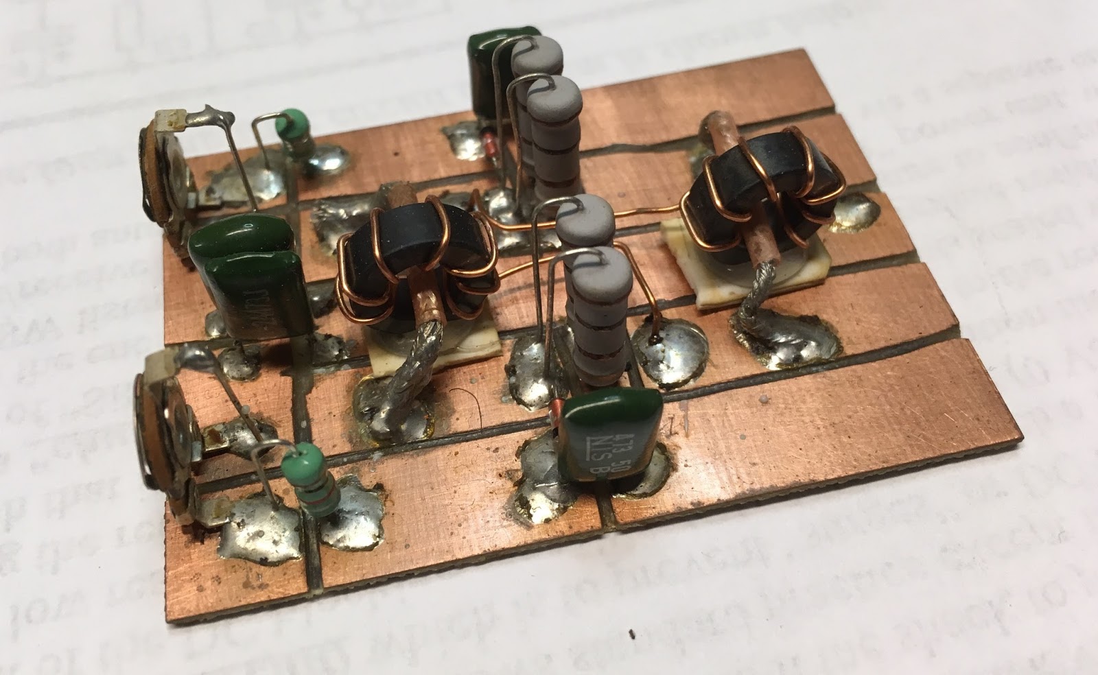
W3JDR's Comment on my post about the DC RX mixer got me thinking. He was right -- my explanation of the mixer action wasn't quite complete, especially as far as switching mixers are concerned. I remembered that I had written about this in the SolderSmoke book. Below you can see the part of the book in which I discuss switching mixers. Realize that the two diodes in F5LVG's mixer play the same role as the two gates in Leon's circuit. It will be worth your while to sit down with Leon's circuit diagram, his frequency chart, and a ruler and really go through this so you can SEE and really understand how the two gates (or switching diodes) generate sum and difference frequencies.
-----------------------
I
guess I still yearned for clarity and intuitive understanding... Time and time again, as I dug into old
textbooks and ARRL Handbooks and
promising web sites served up by Google, I was disappointed.
Then I found it.
It
was in the Summer 1999 issue of SPRAT, the quarterly journal of the G-QRP Club. Leon
Williams, VK2DOB, of Australia
had written an article entitled “CMOS Mixer Experiments.” In it he wrote, “Generally, mixer theory is
explained with the use of complicated maths, but with switching type mixers it
can be very intuitive to study them with simple waveform diagrams.”
Switching
mixers apply the same principles used in other kinds of mixers. As the name
implies, they switch the mixing device on and off. This is non-linearity in the extreme.
Not
all mixers operate this way. In
non-switching mixers the device is not switched on and off, instead one of the
signals varies the amount of gain or attenuation that the other signal will
face. And (as we will see) it does this in a non-linear way. But the basic principles are the same in both
switching and non-switching mixers, and as Leon points out, the switching
circuits provide an opportunity for an intuitive understanding of how mixers
work.
Let’s
take a look at Leon ’s
circuit. On the left we have a signal
coming in from the antenna. It goes
through a transformer and is then applied to two gate devices. Pins 5 and 13 of these gates determine
whether the signals at pins 4 and 1 will be passed on to pins 3 and 2
respectively. Whenever there is a positive signal on gate 5 or on gate 13,
signals on those gaps can pass through the device. If there is no positive signal on these
gates, no signals pass. Don’t worry
about pins 6-12.
RF A
is the signal going to pin 4, RF B is the “flip side” of the same signal going
to pin 1. VFO A is a square wave
Variable Frequency Oscillator signal at Pin 5. It is going from zero to some
positive voltage. VFO B is the flip
side. It too goes from zero to some
positive voltage.
Look
at the schematic. Imagine pins 5 and 13
descending to bridge the gaps whenever they are given a positive voltage. That square wave signal from the VFO is going
to chop up that signal coming in from the antenna. It is the result of this chopping that gives
us the sum and difference frequencies.
Take a ruler, place it vertically across the waveforms, and follow the
progress of the VFO and RF signals as they mix in the gates. You will see that whenever pin 5 is positive,
the RF signal that is on pin 4 at that moment will be passed to the
output. The same process takes place on
the lower gate. The results show up on
the bottom “AUDIO OUTPUT” curve.
Now,
count up the number of cycles in the RF, and the number of cycles in the
VFO. Take a look at the output. You will
find that that long lazy curve traces the overall rise and fall of the output
signal. You will notice that its
frequency equals RF frequency minus VFO frequency. Count up the number of peaks in the choppy
wave form contained within that lazy curve.
You will find that that equals RF frequency plus VFO frequency.
Thanks Leon !
Labels:
DC Receiver Build,
France,
GQRP,
mixer theory,
SPRAT,
UK
F5LVG's Glue-Built Mixer Transformer
One thing I forgot to mention: In Olivier F5LVG's DC receiver article back in SPRAT 100, he casually mentioned building a transformer for his mixer by taking two inductors of the appropriate values and GLUING THEM TOGETHER. What a great idea! I had to try it. I did. Picture above. It worked in my Ceramic DC receiver, but the trifilar transformer from Farhan in India worked better. Perhaps the coupling was tighter. But hey, it worked. Three cheers for Olivier.
Labels:
DC Receiver Build,
France,
mixer theory
Sunday, January 28, 2018
Building the Ceramic Discrete Direct Conversion Receiver #4 -- The Mixer
I think the most important stage of a direct conversion receiver is the mixer. This is the stage that takes the RF energy coming in from the antenna and -- in one fell swoop -- turns it into audio.
It is important to understand how this happens. I go into this in some detail in the SolderSmoke book. To summarize:
1) You have two signals going into a non-linear device. The way in which the smaller signal passes through the device -- how much it is amplified or attenuated -- depends on the instantaneous value of the larger signal. We are not just adding the two signals together.
2) The waveform that comes out will be a complicated repeating waveform. We know from Fourier that any complicated repeating waveform can be broken down into sine wave components.
3) When you analyze the complicated repeating waveforms coming out of the mixer, you will find that the sine wave components include a frequency that is the sum of the two inputs and another that is the difference between the two.
So lets suppose we have a non-linear device. We send in a signal from our oscillator at 7061 kHz. Coming in from the antenna we have a signal at 7060 kHz. The non-linear device will produce outputs at 14121 kHz (sum) and at 1 kHz (difference). We are interested in the difference frequency. We can HEAR that one. We feed it into our audio amplifiers and we can copy the Morse Code coming in. It will sound like a 1 kHz tone going on and off as the operator at the distant station presses his code key. (We don't really have to worry about the 14121 kHz signal -- it is easily eliminated by filters and would never make it through our audio amplifiers. And in any case we could not hear it.)
What can we use as a non-linear device? In this receiver we will use diodes. Diodes are extremely non-linear devices. They can be used as on-off switches, with one of the signals determining if they are on (conducting) or off (not conducting). When used like this they are "switching mixers." In essence, a larger, controlling signal from the VFO will be turning the diodes on and off. Thus the signal coming in from the antenna will be chopped up by the switching action of the diode being turned on and off. This is non-linear mixing at its most extreme. It will definitely produce the sum and difference products we are looking for.
We could build the mixer with just one diode. You could apply the VFO signal to the diode to turn it on and off, and then feed the signal from the antenna into the same diode. You would get the sum and the difference product out the other end. You will see very simple direct conversion receivers intended for use in software defined radio schemes using just one diode. But this kind of circuit has a couple of serious shortcomingsq: it is susceptible to "AM breakthrough" and it is "lossy."
The circuit we are using addresses these problems by using two diodes. To reduce loss, one conducts during half of the oscillator signal's cycle, the other during the other half. Here LTSpice is ueful. You can model this mixer and see in the simulator how each of the diodes handles half of the oscillator RF cycle, with both contributing to the AF signal we want at the output (the difference frequency). (The schematic above is from LTSpice but it is not ready for simulation. For this you should replace the variable resistor with two fixed 500 ohm resistors, and add two oscillators -- one with the weak incoming RF signal and the other the strong local oscillator signal.)
The AM breakthrough problem is also addressed by the use of two diodes. Here's the problem: If you are on 40 meters, there will be strong shortwave AM broadcast signals coming in from your antenna. Some will be so strong that they will get past your front-end filtering. If you were using just one diode, that diode might demodulate the AM signal -- the AM carrier would mix with the AM sidebands and you would have an undesired audio signal heading for your AF amplifiers. Many of us have experienced this -- you are trying to listen to ham radio SSB signals, but you can hear China Radio International playing in the background.
The two diodes take care of this easily. Look at the way an AM signal would reach the diodes. The carrier (and its sidebands) going through the top diode will be 180 degrees our of phase with the signal going into the lower diode. But the output of the diodes are joined together. They will cancel out. We say that for the RF signal coming through from the antenna, the circuit is "balanced." That signal -- in this case the undesired AM signal -- will cancel out at the junction of the two diodes.
But to understand this circuit you must see what is NOT cancelled out. The signal from the VFO is hitting each diode with the SAME polarity at the same time. Look at the 1k variable resistor. So the signal from the VFO will NOT be cancelled out at the output. Nor will the mixing products produced in the diodes. That last sentence is the key to all of this. The sum and difference products that result from the mixing of the signal from the antenna and the signal from the VFO SURVIVE. They are not cancelled out.
We can easily select the one we want. An RF bypass capacitor connected from the output of the mixer to ground will get rid of most of the VFO signal (7061 kHz) and most of the sum product (14121 kHz) while passing the audio to the AF amplifiers.
When I built this detector I used a trifilar toroid out of a box of them that Farhan left with me back in May. I used two of the windings secondary and one of the windings for the primary. You might want to make a more simple transformer using an FT-43 type core. I recommend W8DIZ as a source.
I hope this explanation helps, and I hope I got it right. Let me know if you see any errors in my explanation. Tinker with the circuit when you build it. You should be able to get it going.
Complete Schematic |
Labels:
DC Receiver Build,
direct conversion,
mixer theory
Sunday, January 21, 2018
Mike Rainey and Heavy Metal AM Phone
Michael Rainey AA1TJ wrote:
I can tell you exactly what's going on here. I'd just received a license upgrade from "Novice" to "General." My new license granted radiotelephone privileges and I was eager to try them out.
In the early 1970's no self-respecting amateur radio operator would dream of using amplitude modulation (AM) on wavelengths above 10m. It wasn't illegal, rather, it was frowned upon due to bandwidth issues, among other things.
But in my excitement - and in the time-honored spirit of, "don't ask permission, ask forgiveness" - I tuned my clunky, Heathkit DX-100 to the 40m radiotelephone band and began calling CQ on AM. Everyone that I contacted was very polite, but to the man they all mentioned how "odd" it was to hear an AM signal on 40m. I eventually took the hint, but not before I'd figured out that yakking on a microphone wasn't my thing after all. Morse telegraphy was my first and enduring love.
-------------------------------------
I think Michael's next phone transmitter was that voice-powered rig that he used in an attempt to cross the Atlantic with the only power source being his vocal cords. But even there, he was using his voice to send Morse.
Labels:
AM,
CW,
DX-100,
Rainey -- Michael
Saturday, January 13, 2018
SolderSmoke Podcast #202 Cover-Rig, SKN, Pete's Vector Boards, uBITX, K1BQT rig, MAIL
SolderSmoke Podcast #202 is available:
http://soldersmoke.com/soldersmoke202.mp3
13 Jan 2018
Opening music from Shel Silverstein and Dr. Hook and the Medicine Show.
http://soldersmoke.com/soldersmoke202.mp3
13 Jan 2018
Opening music from Shel Silverstein and Dr. Hook and the Medicine Show.
On the Cover of the Rolling Stone or On the Cover of SPRAT magazine.
Travelogue and Weather Report
-- Bill's trip to the Dominican Republic. SWL on the beach. Return to the ice box.
-- Dramatic events in California.
-- Reading Chinese Sci Fi with lots of radio in it. "The Three Body Problem" by Cixin Liu
Straight Key Night. IN QRP MODE THANK YOU. With nephew Jeffrey. Annual event -- worked Jim W1PID friend of Mike Rainey.
Steve Murphy and Jeff Damm on QSO Today. FB.
Oh your rig is homebrew? "It must be propagation."
ER Reading about G3UUR
Hams avoiding 60 meters due to 100 watt limit. SAD.
Bill's Bench: Continuing series on the Ceramic Discrete DC receiver. Described the oscillator and the AF amp. Next we will do the Mixer. The most interesting stage. Nephew John Henry and niece Helena visiting today.
Pete's bench. uBITX adventures.
The K1BQT IC transceiver.
The Vector Board building technique. See http://n6qw.blogspot.com/
MAILBAG
Paul KA5WPL Looking for project with his son. Sawdust. Thanks again Steve Silverman.
Chris Waldrup OM PBJ thanks for the gift
Pete in contact with Sven Johnson
Chuck KE5HPY sent us picture of fashion model with boatanchors in background Grayson recalled 73 magazine covers...
Pete WB9FLW Bilateral SBE-33 ad "with inherent stability" That's the best kind!
Bruce KK0S experimenting with AF amps for the DC receiver
John KE5ETX Attempting CBLA
Labels:
CW,
SolderSmoke Podcast,
SPRAT
Friday, January 12, 2018
Saturday, January 6, 2018
Steve Murphy N8NM on QSO Today

Don't miss this one. Listen here:
https://www.qsotoday.com/podcasts/N8NM
My notes:
-- On a Stingray bicycle patrol on garbage night, looking for radio parts. FB Steve!
-- Started with SWL. A fine radio pedigree.
-- Had an R-390A at age 16.
-- Uses an LC meter to check on toroid windings.
-- Steve: Thanks for the kind words about inspiration.
-- Manhattan And Ugly. Mugly!
-- Planker! Better on a Board!
-- Form Factor First, but then it never fits! Al Fresco!
-- Packages arrive from China faster than they go across Israel.
- - E-bay as a really good source for parts.
-- Oh god, not an S-38E. Stop torturing yourself Steve.
-- N8NM: Radio Renaissance Man: Runs a 2 meter repeater network. Thinking of 900 MHz.
-- Papa Legba -- I got it from a W9SCH via SPRAT. He got it from Voodoo.
N8NM is chickenkiller.com FB.
-- Moderation? Ha! Good luck with that!
-- An Electromagnetic Playground where Failure has No Consequences. Well put.
-Happy New Year Eric and Steve! Thanks to both of you.
Labels:
China,
Guth -- Eric,
Israel,
Murphy -- Steve,
Old radio
Subscribe to:
Posts (Atom)