Podcasting since 2005! Listen to Latest SolderSmoke

Wednesday, January 30, 2019

Putting the QCX on SSB


Here is a very cool mod to Hans Summers' amazing QCX CW phasing transceiver.  This rig seemed to have been crying out for an SSB mod.  Guido has come up with a very clever way to put this rig on phone. 


Guido PE1NNZ wrote: 
Jan 28   2019

Over Christmas I have been playing around with a simple modification that transforms the QCX into a Class-E driven SSB transceiver. With this setup I have been able to make several SSB contacts and FT8 exchanges across Europe and so far this experiment is working reasonable well. It can be fully-continuous tuned through bands 160m-10m in the LSB/USB-modes with a 2200Hz bandwidth, provides up to 5W PEP SSB output and has a software-based full Break-In VOX for fast RX/TX switching in voice and digital operations.

The SSB transmit-stage is implemented in a completely digital and software-based manner: at the heart the ATMEGA328 is sampling the input-audio and reconstructing a SSB-signal by controlling the SI5351 PLL phase (through tiny frequency changes over 800kbit/s I2C) and controlling the PA Power (through PWM on the key-shaping circuit). In this way a highly power-efficient class-E driven SSB-signal can be realized; a PWM driven class-E design keeps the SSB transceiver simple, tiny, cool, power-efficient and low-cost (ie. no need for power-inefficient and complex linear amplifier with bulky heat-sink as often is seen in SSB transceivers).

An Open Source Arduino sketch is used as the basis for the firmware, a hardware modification bypasses the QCX CW filter and provides a microphone input in-place of the DVM-circuit; the mod is easy to apply and consist of four wires and four component changes and after applying the transceiver remains compatible with the original QCX (CW) firmware.

This experiment is created to try out what can be done with minimal hardware; a simple ATMEGA processor, a QCX and a bit of signal processing to make SSB in an artificial manner. It would be nice to add more features to the sketch, and see if the QCX design can be further simplified e.g. by implementing parts of the receiver stage in software. Feel free to experiment with this modification and let me know your thoughts or contribute here: https://github.com/threeme3/QCX-SSB

73, Guido
PE1NNZ


Schlitz Beer and Ham Radio


Another necktie in the hamshack. Can anyone identify any of the gear? 

Tuesday, January 29, 2019

The Vintage SSB Net


This group looks like a lot of fun.  I like how they record the entire session and put it on the web.  


You should listen to their "preamble."  It describes the purpose of the net and the group's belief system.  Very well done.  These are our people!  I will request a full transcript of this important and inspirational document. 

Here is a link to a reading of the net preamble:


"Smoke and flame may occur at any time!" 

DON'T BE A VIOLATOR! NO MODERN RIGS!  

Monday, January 28, 2019

HT-37/2B QSO with K6ZA (three short videos)


On January 23, 2019 on 20 meters I talked to Barry K6ZA.  He is near San Francisco.  I was running my Hallicrafters HT-37 with my Drake 2B.  I was really pleased to discover that the guy I was talking to loves these two pieces of gear as much as I do.  

Barry said he wished I could record his voice coming out of the HT-37.   My iPhone came to the rescue.  


The Secret Life of Machines -- Radio


We had this on fhe blog three years ago, but it is so good that it deserves a second posting. 
Thanks to our old friend Stephen Walters for reminding us of this gem.  There is so much soul in these old machines. Thanks Stephen. 

Sunday, January 27, 2019

Godzilla, an SP-600, a D-104, and a Turner SSB+2 Transistorized Mic


We were in a restaurant last week and this trailer played on a TV that was all the way across the room.  The SP-600 caught my eye.  I once had one of those, but chickened out when I read about the horrors of black-beauty cap replacement.   There is also a D-104 in the trailer (several of those are with me now).  And the girl is transmitting with a Turner SSB+2 Transistorized mic -- I have one of those also. 

Thomas K4SWL over at The SWLing Post  notes that the SP-600 Tuning Dial appears to have been modified.  I'm thinking the wanted it to look like some sort of transmitter output meter. 

I think I can also see some sort of Collins antenna tuner.   

Any ideas on whose shack this all comes from?   It looks like a real ham shack.  

From the trailer, it appears that the ham gear somehow helped us establish contact with Godzilla, who then went on to save the planet.  I hope.  ONCE AGAIN, HAM RADIO SAVES THE DAY! 

The ham radio stuff is in the first minute or so of the trailer. 

Saturday, January 26, 2019

Rescued at Sea! Saved by an S-38!

Just click on the ad to enlarge it. 

Another cartoon relayed via the Facebook page of Jeff Murray K1NSS.   

Sure, there was a rescue at sea, but what about all the casualties caused by the AC/DC "widow-maker" S-38 power supply? 


Friday, January 25, 2019

When Hams Wore Neckties, and AM Transmitters Were in the Living Room

Jeff Murray K1NSS had this on his Facebook page.  Great stuff.  But I felt like yelling out, "Stay in the basement OM!  Stick with your haywire rig!" 

Monday, January 21, 2019

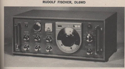
A Homebrew HRO Dial by DL6WD, Homebrew Hero


Take a look at that beautiful rig in the bottom of the cover pictures. (A closer shot appears below.)  That is an HRO dial, right?  Or is it?  

No, it is not.  In the picture we see the homebrew receiver designed and built during the 1960s by Rudolf Fishcer, DL6WD.  It is magnificent in every respect.  Because I have been working with the HRO dial and gearbox given to me by Armand WA1UQO, the tuning dial on this receiver caught my attention. 

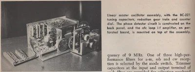
Here is what DL6WD says about this part of his project:  "The main tuning gear was built around a BC-221 tuning capacitor and reduction gear. The counter dial and tuning knob are the result of four weeks of labor, The counter dial reads in tens of kHz, where the main tuning knob has a calibration of 200 Hz per division, from an HRO inspiration."  The counter is in the little window to the upper left of the tuning knob. The window to the upper right is a phase-lock indicator. (See below.)

By the way, by the time DL6WD got finished with this all solid state receiver it weighed in at 52 pounds.  Rudolf noted that "excessive shielding pays in electrical performance, but not in weight!" 

DL6WD earns the title "Homebrew Hero."


Saturday, January 19, 2019

Switching to a Mechanical Filter from 1967 for my HRO-ish Receiver (with video)

From RSGB Handbook 1982

Having overcome the difficulties with the National NPW Dial and Gearbox, I turned my attention to the 455 kHz filter.  I had been using this old Toyo CM - 455 kc filter (Date stamped August 1969).  CM stands for "Crystal-Mechanical."  These filters are hybrid with some of the features of a crystal filter and some of the features of a mechanical filter. For more details go here: 
https://soldersmoke.blogspot.com/2016/04/the-meaning-of-cm-in-toyo-cm-455-filter.html

I was disappointed by the CM filter.  It seemed very lossey, and it just didn't seem to be of sufficiently high Q -- it seemed very broad. I could hear the other side of zero beat.  It was barely a "single signal" receiver,  and being "single signal" is the whole point of a superhet. 

I remembered that Pete Juliano had sent me a Japanese-made 455 kc mechanical filter. Maybe this would do better.  Last night I did a quick comparison test and -- wow -- Pete's filter was much better.  The Fifth Edition of the RSGB Handbook seems to agree with my assessment, noting that mechanical resonator filters were superior to the Crystal Mechanical hybrids (see pages 4.17 and 4.18) 

Pete's filter is from the Kokusai Electric Company.   Part# MF 455 ZL.  (Date stamped May 1967). "ZL"indicates lower sideband.   I checked and indeed the passband goes from just above 452 kc up to about 454.5 kc.  This is a 40 meter receiver and SSB on 40 is LSB, so this filter would work perfectly right?  Not so fast!  Sideband inversion had to be considered.  

I was running my VFO from about 7455 to 7755 kHz.  This means that the modulated incoming signal would be SUBTRACTED FROM the VFO signal to get to  the 455 kHZ IF.  And when that knd of subtraction happens, we have sideband inversion.  The LSB signal will look like a USB signal when it reaches the filter. 

My BFO was running right at 455 kHz, using a ceramic resonator at that frequency. I briefly considered just shifting it down to 452 kHz, but this proved to be difficult.  Then I got a better idea. 

I could just shift the VFO down to 6545 to 6845 kHz.  This would mean that the VFO frequency would be subtracted from the incoming modulated frequency.  There would be no sideband inversion.  I had been thinking about doing this frequency shift anyway, thinking that VFO stability gets better as you go lower in frequency. 

REMEMBER THE RULE:  If you are subtracting the modulated (signal) frequency from the frequency of the local oscillator or VFO, only then will you have sideband inversion.  See: 
https://soldersmoke.blogspot.com/2015/05/sideband-inversion.html

Moving the VFO was easy. I am using a variable capacitor with several variable caps on the same rotor.  I just moved from the smallest variable cap to the middle variable cap -- this added capacitance to the system and lowered the frequency.   I also added three additional turns on the coil.  This put me very close to where I needed the frequency to be.  I added one additional 9 pf cap and this put the VFO freq right where I wanted it. 

I was really  glad to include Pete's filter in this receiver.   The mechanical resonator technology fits very well with the very mechanical old-tech theme of this project (it already had a gearbox -- a mechanical filter seemed to fit right in).   It is a fascinating device -- it is almost like having a set of tuning forks all tuned to 455 kc (see above for the RSGB description of how it works).    And having it from from Pete adds a TREMENDOUS amount of mojo, juju, and soul to the new machine. 

Icing on the cake: As I type this, I am listening to Fred K3ZO converse in Spanish with hams all through South America.  Fred preceded me by three decades at the U.S. Embassy in Santo Domingo, but when I got there the local hams were still talking about him  -- he was much loved and admired by the Dominican hams.  TRGHS. See Fred's story here (scroll down a bit): http://www.gadgeteer.us/DRDISP.HTM 


Thursday, January 17, 2019

Solar Cycle 25 -- The High Frequency Oracle Has Spoken (THFOHS!)

Not quite as authoritative as a spoken message from the The Radio Gods themselves (as in TRGHS), but the HF Oracle seems to be well connected.   Time to start planning for Moxons and Hex Beams!  

Read the full poetic report from the Oracle here: 

https://forums.qrz.com/index.php?threads/the-hf-oracle-prognostication-for-solar-cycle-25.626433/

Wednesday, January 16, 2019

National Dial and Gearbox Problem Resolved

Thanks to all who offered advice and assistance.  With help from you guys -- and  especially from Pete Juliano N6QW -- I think I have this fixed.

Pete was right -- the problem was really with the variable capacitor.  The one I was using was kind of stiff and irregular in its motion.  I found another one in the junk box that was easier to turn (it has one set of ball bearings).  This fixed most of the problem.

I also spent more time making sure the shaft of the cap lined up perfectly with the shaft of the gear box.  This also helped a lot.

I realize now that some of the "stickiness" that I occasionally feel while tuning may be coming from the dial -- not from the gear box.  It looks like my dial took a hit that slightly bent one portion of it.  It seems that the numbers have a bit of trouble clicking over on that portion of the dial. Some lubricant may help there.  But I can live with it.

The receiver now tunes very smoothly and I can go right back to a frequency and find the signal exactly where I left it.  There does seem to be a very slight difference depending on whether I "approach from above" or "approach from below" -- but this is not a big deal.

Check out the pictures of the receiver and the VFO.  Note the "cardboard from a coat hanger" coil form.  The winding is held in place with nail polish varnish.  I had planned on having the variable cap, the coil , and the associated fixed caps all in a box for better thermal stability, but the VFO is very stable even without the box.  I have the VFO running 455 kc ABOVE the signal frequency.  It runs from about 7455 kc to about 7800 kc.  I could have set it up to run 455 kc BELOW the signal freq.   That would have made it a bit more stable (it is easier to attain VFO stability at lower frequencies) but VFO is so stable that I probably won't mess with it. I followed DeMaw's rules:  Physical stability, NP0 caps.  For the NP0 caps, put several of them in parallel to get the desired capacitance value. Keep heat-producing active components away from the coils and caps.   

Thanks again to Armand WA1UQO for giving me this amazing piece of radio history. And thanks to Tim Sutton for the big box that holds this receiver. 

James Millen knew what he was doing.  See: http://www.isquare.com/millen/millen-page.htm


Designer: Douglas Bowman | Dimodifikasi oleh Abdul Munir Original Posting Rounders 3 Column