Podcasting since 2005! Listen to Latest SolderSmoke

Saturday, March 18, 2023

Needed: More Info on the Cuban Islander or Jaguey DSB Transceivers

CO6CBF: "I began operating on the HF bands using homebrewed radios. Mainly on CW running just 10 Watts. My very first phone transmitter was a controlled carrier AM modulator for the 160m band using tubes and components salvaged from an old TV set."

My good friend Dean KK4DAS has built a DSB rig for 10 meters and is working a lot of DX with it.  Peter Marks in Australia has also jumped into the DSB game.  A few of the students we are working with at the local high school may get their General Class licenses and convert their Direct Conversion receivers to Double Sideband transceivers. 

All of this has caused me to reminisce about the famous Cuban Double Sideband rigs. Homebrew Hero Arnie Coro CO2KK used to talk about these rigs on his "DXers Unlimited" program on Radio Havana Cuba.   But Arnie recently passed away, and with him I think a lot of the background info on the Cuban DSB rigs has also disappeared. I find very little about these rigs on the internet -- I have not been able find a single picture.  The Radio Havana Cuba archive of Arnie's shows has disappeared.  

Back in February I talked to Yulian CO6YI on 20 meters about the Cuban DSB rigs.  He said he had a lot of background info on them, and said he would try to send it to me.  I hope he is able to do this. 

The results of my initial Googling appear below.  There has to be more out there. I'm thinking that there must be a lot of background info on the Islander and Jaguey rigs sitting on the hard drives of radio amateurs.   It is time to give this info wider circulation.  Please send me any info you have on these rigs.  Of particular interest would be schematic diagrams and photos of the rigs.  


https://www.paara.org/newsletter/2000/graph200007.pdf


Date: Mon, 22 Mar 2004 17:48:59 -0500
From: "Prof. Arnaldo Coro Antich" 

Subject: Re: GB> 6EH7 vs. 6EJ7 as RF Amplifier

 Dear amigo Chris:
You are absolutely right !
EF184 is the best pentode for RF amplifier duty...
But, let me ask you something... have you thought
about the ECC88 and the even better ECC189 dual
triodes that were designed for TV tuner work, and
that incidentally were also about the last vacuum tubes
ever designed from ""scratch"" until Phillips and other
European manufacturers stopped from making
receiving type vacuum tubes.
The ECC189 is simply wonderful for a front end !!!
I am sure that you are aware of our limitations here at
my QTH regarding the possibility of obtaining solid
state modern devices... so we still make ""new"" ham radio rigs using mostly
vacuum tubes...
We even still make a version of "" The Islander"" a DSB transceiver with
direct conversion vacuum tube receiver...
Tube lineup is
EF184 RF amp
ECH81 product detector
ECH81 triode section not used
ECL82 triode audio preamp
ECL82 pentode audio output
6AH6  VFO ( Russian equivalent 6*5P )
Audio filter provided by good working brain of
operator !!!
Keep up the good work amigo !!!
73 and DX
YOur friend in Havana
Arnie Coro
CO2KK

http://ibiblio.org/modena/GLOWBUGSpiobaire/glowbugs.piobaire.weekly.html

Today’s first question came from a long time listener in India. Rajiv 
tells me that at this moment he is not able to pick up our station on 
the shortwave bands, and he rightly assumes that this is because of the 
very low solar activity… but Rajiv who lives in the garden city of 
India, Bangalore, the home of the nation’s electronic and other high 
tech industries, is able to read the scripts of the program that are 
made available to several short wave listeners clubs e-mail distribution 
lists. Rajiv tells me that he wants to obtain the electronic files of 
the Super Islander amateur radio transceiver to compare the circuit 
diagrams and design philosophy with a similar project that is becoming 
very popular among Indian radio amateurs.
Ok amigo Rajiv… I have already sent you all the files including some 
nice digital photos of the first prototype of the Super Islander, that 
as you will see, has two final amplifier options , one built using NPN 
RF power transistors, and the other one using two vacuum tubes that are 
very easy to find here in Cuba from recycled TV sets. The Super Islander 
is a single band transceiver that can be built for the 160, 80 or 40 
meter bands. Here in Cuba amigo Rajiv, the most popular amateur band 
nowadays is two meters, using the FM narrowband mode, and the second 
most popular band among Cuban radio amateurs is 40 meters, that’s why 
most of the Super Islanders are built for operating between 7.000 and 
7.150 kiloHertz.  The double sideband signal generated by the Super 
Islander simple circuit is very stable, and very few if any radio 
amateurs that contact stations using the Super Islander are able to 
detect that it is a double side band and not a single side band signal 
what they are hearing. One of the most outstanding features of the Super 
Islander single band amateur radio transceiver is that it is modular, so 
those who want to build it, are able to build and test each module as a 
single project, and after all the modules are fully tested, then they 
are easily wired together . The parts count, that is the number of 
components required to build a Super Islander was kept intentionally as 
low as possible, both to simplify its construction and to increase the 
reliability. I hope that amigo Rajiv in Bangolore , India will be able 
to make good use of the Super Islander’s files, and maybe even go ahead 
and build one , as the parts required are almost universally available, 
because that was one of the design requirements that I set when starting 
the  Super Islander project more than fifteen years ago….You can learn 
more about this simple amateur band transceiver by sending a request for 
the Super Islander files to arnie@xxxxxx … I will send it as a dot zip 
file and you will be able to see circuit diagrams, photos and full 
descriptions of the different modules of this nice little rig, that has 
proven itself under the most difficult circumstances, like handling 
emergency communications links during tropical storms.
http://www.hard-core-dx.com/hard-core-dx/2007/msg02587.html


Beginners generally build one of two radios; the vacuum tube Islander or the solid state Jaguey. The Islander is a DSB/CW Cuban design using a very clever low parts count circuit and a direct conversion receiver. The Jaguey, named for the Jaguey Grande Radio Club in Matanzas province, is a generic design, with a DC receiver, DSB and CW, using solid-state components. Many of its ideas are from Wes Hayward's W7ZOI's Solid State Design for the Radio Amateur. The lack of mechanical filters or quartz crystals to homebrew SSB filters made Cuban designers CO5GV, CO2JA and CO2KK choose a DSB and CW rig. Fitted with good quality capacitors for the VFO, it works quite well from a 12-volt car battery in hurricane emergencies.

Thursday, March 16, 2023

A Very Cool Video with NanoVNA, FFT, LC circuits, W2AEW, CuriousMarc, Back-to-Back 1N4148s, and String-Powered Gyroscopes


Don't let the scary nuclear chemistry title put you off -- there is a LOT of very familiar homebrew stuff in this video.  You will feel right at home.  Many of the resonances take place in the ham bands.   The CBLA may have to get involved here. 

Thanks to Chuck WB9KZY for sending this. 

And check out Ben's video on is best projects from the last 10 years: 

Wednesday, March 15, 2023

Listen to Pete Juliano on His Daughter Gina's Podcast -- Pete Discusses Rock Music and Life

https://podcasters.spotify.com/pod/show/gina-juliano/episodes/Mission-To-Music-This-Is-What-You-Need-To-Do--Episode-2-e20a6bs/a-a9ft547

This is really cool.   Pete Juliano N6QW is interviewed by his daughter Gina.  (You can hear it by clicking on the link above.) Gina has a podcast about the music industry called Mission to Music.  I liked it a lot.  I never realized that Pete was such big fan of rock music.  I was especially touched by Pete's closing comments on his words to live by:  "Always tell the truth and do the right thing."  Words to live by indeed.   Thanks Pete.  And thanks Gina!  

Tuesday, March 14, 2023

Fixing the Tuning Problem in the High-School Direct Conversion Receiver (with video)

Here is the problem: 

For the capacitive element in the LC circuit we have essentially two 660 pF caps in series.  This results in a total capacitance of 330 pf.  I measured 362 pF.  

To get a resonant frequency of 7.0 MHz with 362 pF we need 1.428 uH.

To get 1.428 uH on the PTO coil form we need about 21 turns of wire. 

21 turns on our coil form yields 1.440 uH and resonates with 362 pf at 6.9708 MHz

That’s pretty close to what we need, but the problem arises when we screw in the brass tuning screw.   This reduces the inductance and raises the frequency.  Putting the screw all the way in reduces the inductance to 1.138 uH resulting in a resonant frequency of 7.8414 MHz.  So with a coil this large (that we must use if we want to tune down to 7.0 MHz) we end up with a tuning range that is far too large.  We only need 7.0 to 7.3.   In effect, this means that we end up using only a small portion of the tuning range:  We can turn the screw approximately 34 times, but only 6 turns keep us within the range of 7 to 7.3 MHz (the 40 meter band).  There is about 50 kHz per turn of the dial.  This makes tuning difficult.  It becomes more difficult to separate stations and tune them in.  It would be better if we could tune across the band using more turns of the dial.  At least 15 turns of the dial would be nice:  That would mean about 20 kHz per turn.  But how can we do this? 


Possible solution #1:  Steel screw with tighter pitch on the turns.

Just using a steel screw slows the tuning rate down.  In a normal PTO we increase the inductance (and reduce the frequency) by gradually introducing a ferrous material that increases the inductance of the coil, pushing the frequency of oscillation down.  But our brass screw is non-ferrous.  This means that putting it into the core does not change the permeability of the coil.  The permeability of brass is the same as that of air.

What does happen,  however, is that introducing the brass screw into the coil causes currents to flow in the screw.  These are called eddy currents.  In effect they become shorted secondary coils.  And they have the effect of lowering the inductance of the coil – this is why the frequency of the oscillator increases as we screw in the brass screw.

When you use a steel screw you get both effects: As you screw it in, eddy currents flow in the screw, reducing the inductance and increasing the frequency of oscillation.  But you are also introducing ferrous material – this pushes in the opposite direction, increasing induction and lowering the frequency of oscillation.  I think the eddy current effect dominates, but the increase in permeability pushes in the opposite direction.  This means that with a steel screw you have to use more turns to cover the same frequency range.  And that is what we want. 

For example, using the same coil, with screw of the same thread pitch (the same nuts), with both screws ten turns in, one turn of the brass screw moved the inductance .014 uH.  The same single turn of the steel screw only moved the inductance .005 uH.  So just because of metallurgy, the steel screw will lead to a lower (better) tuning rate.  I used a Hillman 45479 screw that is steel with a Zinc (anti-corrosive) coating. https://www.amazon.com/Hillman-Group-45479-Phillips-Machine/dp/B00JDU0PZI   and be sure to get the correct nuts: https://www.amazon.com/Hard-Find-Fastener-014973241704-Piece-100/dp/B00L1L76E0/ref=sr_1_4?crid=UOPEF2HLAD75&keywords=1%2F4-28+nut&qid=1678881552&s=hi&sprefix=1%2F4-28+hex+nuts%2Ctools%2C71&sr=1-4

But there is more:  steel screws are also available with tighter (#28) thread pitches. The Hillman 45479 uses this tighter thread pitch.   This too means that more turns are needed to move through the same tuning range.  Again, that is what we want. 

I found that using a steel screw with #28 thread pitch allowed for the coverage of the 40 meter band in approximately 11 turns of the dial.  That is much better than what we got with the brass screw:  About 27 kHz per turn instead of the 50 kHz per turn that we got with brass.  But it is not quite good enough.   It would be better if we could use the entire range of that PTO coil form.

Solution Two:  Add a fixed inductor in series with the PTO coil. 

After some noodling, I decided to split up the inductor:  A portion of it would remain fixed, the other portion would continue to be tunable.

I estimated that I was starting out with a coil of about 1.428 uH.  So I just put a 1 uH choke in series with the variable inductor and reduced the variable coil to about .428 uH (about 9 coil turns).  This worked, but it worked a bit too well!  It would not tune the entire 40 meter band.  So I figured I needed less fixed inductance and more variable inductance.  I found an air-cored coil in my junk box and cut it so that it measured about .650 uH.  I added turns to the variable coil, going to a total of 15 turns.  This REALLY worked well and yielded the 26 or 27 turns to tune across 40 meters that you can see in the video.

TWEAKS: 

Later, I tweaked it a bit more:  With 15 turns of #22 wire on the variable inductor, a steel screw tuned from .791 uH (screw out) to .662 uH (screw in).  I put one additional turn on the fixed inductor, making it .749 uH, or about 8 turns of #22 (wound tighter on a cardboard tube from a coat hanger than was the coil on the variable inductor).   With these coils I could tune from 6.9772 to 7.386 MHz.  That's a bit more than we need but this allows us to keep the tuning away from the ends of the coil where tuning is more likely to become non-linear.  I am able to go from 7.0 to 7.3 MHz in 23 turns of the dial.  And the tuning is quite linear:  The first turn from 7.0 MHz moves the frequency 12 kHz.   At the mid-point of 7.150 MHz, one turn of the dial moves the frequency 12 kHz.   At the high end, going down from 7.3 MHz, one turn of the dial moved the frequency 11 kHz.  That, for me, is VERY linear tuning.  You probably will have to adjust the coils a bit (just squeezing the turns together or spreading them apart) to get the tuning range where you want it.    

YMMV – Keep it simple!

Like they used to say in the commercials:  Your Mileage May Vary.  There are many ways of doing this.  The objective is smooth tuning across the 40 meter band.  I think that by varying the pitch of the variable coil turns you could get a more linear tuning response (please let us know if you have any luck).  You might also be able to get similar results by changing the amount of capacitance in the feedback network (which is also the frequency determining element in this simple Colpitts oscillator).   But remember that simplicity and a low parts count were also our objectives in this.  This mod adds only 1 part (the fixed inductor), requires the removal of some turns from the main tuning cap, and perhaps the replacement of the brass screw with a steel #28 screw and nuts.  

We might present to the student this problem and our search for a solution.  This would be a good example of how homebrewers work to make their rigs better and easier to use.  It illustrates well the design dilemmas that can come up, and how amateurs like us can come up with solutions. 

Friday, March 10, 2023

Troubleshooting an Intermittent with Mr. Carlson. And Troublesome Tube Re-Branding.


This is a really great video on how Mr. Carlson (VE7ZWZ) did troubleshooting on a tube-type receiver. The problem was an intermittent.  They can drive you nuts, but Mr. Carlson show us how to stay sane. 

-- His use of ordinary observation at the start of the process is very important.  He notices a flickering glow in the voltage regulator tube.  The flickering coincides with the intermittent noise that he is trying to fix.  That is an important clue. 

-- He also can see that the grid of one of the AF amplifier tubes is getting way too hot: grid emission.  That is another important clue.  

-- He checks the grid voltage on the AF amplifier and finds that it is way too low.  It is fine on the other side of the resistor that carries the voltage to the tube.  But it is close to zero at the grid.   This means that the mica capacitors on the grid are suspect. 

-- He uses some fairly esoteric test gear -- a homemade device and an an old Heathkit signal tester -- to check his diagnosis.  They confirm that the mica caps are the problem.  He replaces the caps and the problem is gone.  A very satisfying troubleshoot. 

Mr. Carlson presents us with a lot of good info: 

-- 6K6 tubes were often in fact 6V6 tubes.  And 12AX7s were often 6VJ8s!  Manufacturers were deliberately re-branding tubes. So we shouldn't be surprised if some of our solid state devices turn out to be a bit different from what was promised.  This practice goes way back. 

-- I liked Mr. Carlson's final sensitivity test on the receiver -- he just waved his hand near the antenna connection and we could hear the receiver respond.  Excellent. 

-- Mr. Carlson is very negative about the use of polystyrene caps in oscillator circuits.  But we these simple and cheap caps being used to good effect in oscillators in India.  

-- The leaky and bad micas were a bit surprising.  Carlson speculates that their proximity to heat-producing resistors might have caused the trouble. 

Finally, it is interesting to hear the Canadian pronunciation of radio words:  Solder with the L pronounced (as in the UK).  Farad with the second A long and the final D emphasized (I say it just as the first two syllables of Michael Faraday's last name). 

Thanks Mr. Carlson. 

Tuesday, March 7, 2023

SolderSmoke Podcast #244 PETE IS BACK! TR-7, CK722, BFR106, HP8640B, High-School Receiver, 10 Min TX, MAILBAG


SolderSmoke Podcast #244 Is available:

http://soldersmoke.com/soldersmoke244.mp3

Video version at:

(118) SolderSmoke - YouTube

HE’S BACK! HOORAY! PETE JULIANO N6QW IS BACK! SOLDERSMOKE COMMUNITY WAS SENT INTO A COLLECTIVE FUNK BY PETE’S ABSENCE. ---------------- Pete’s TR-7 (SEE VIDEO ABOVE) CK722 The BFR106
Pete's new blog: https://hamradiogenius.blogspot.com/ ---- Update on the high school project: Mixers made. Harder than they seemed. First QSO with the DC RX. Allan W4AMV Homebrewer TRGHS Ten Minute Transmitter – Better than the MMM! AF4K (SK) crystals. Other supporting projects: Farhan in Hyderabad. Rick N3FJZ, Walter KA4KXX, Andreas DL1AJG Electronics for Biologists. Peter Marks VK3TPM (fighting the siren call of the Si5351) . Steven VK2BLQ built a beautiful one. Daniel VE5DLD will build three of them with his students. Orlando PY2ANE is building one in Brazil. This week: The Bandpass Filter. (Thank you Hans Summers) --- SHAMELESS COMMERCE DIVISION: BECOME A PATRON VIA PATREON. I am posting some fun stuff for the Patrons. AMAZON SHOPPING ADS Now on both the left and right columns. CHECK OUT Mostly DIY RF in the right hand column. ---- My HP8640B Lives to Fight another day. Two new DMMs A low-end Fluke and a AstroAI 6000 Electrolytic Replacement Controversy Continues
Mailbag: -- Dave AA7EE is blogging again! Yea! -- Mike Rainey AA1TJ back in the Hobbit Hole Building a WWVB receiver. -- Farhan is coming to FDIM. -- Tony G4WIF reminds us that 39 bucks for JUST a 60 MHz counter would be great! -- Dave VE3EAC again helped me fix my HP8640B. -- Dean KK4DAS finalizing 10 meter DSB rig. FB. Upgraded my NanoVNA. -- Mike KD4MM giving me a Nano VNA for the SolderSmoke Shack South. -- Ian VK3LA asked what happened to Chuck Adams content. Good question. -- Don ND6T and I have been discussing envelope detection. -- Nick M0NTV working on AM modulators. He has a new video. -- Ciprian YO6DXE built a Ten Minute Transmitter. -- Steve EI5DD Connacht Regional News: https://www.docdroid.net/YJAV800/crnews0223-pdf

Hyderabad DC RX Workshop

Farhan explaining the receiver in Hyderabad

Monday, March 6, 2023

Pictures from Farhan's Hyderabad High-School Direct Conversion Workshops

 
Farhan came up with the idea of having high school students build their own receivers. We followed his lead -- there are now several such projects underway around the world. 


The simple but effective Colpitts circuit that Farhan recommended. 
The PTO tuning idea came out of  his "Daylight Again" transceiver

Oscillation!  

Sunday, March 5, 2023

Farhan's High-School Direct Conversion Receiver Workshops in India


Farhan sent this picture yesterday.   If you look closely you can see the students holding their homebrew 40 meter Direct Conversion receivers.  You can even see that they are using the same kind of PTO coil forms that we are using here.  Farhan reports that 11 receivers were built by 33 students.  A few more are being finished and will soon be active in Hyderabad. 

I was really blown away by this picture.   We are doing the same things on different sides of the world.  Our students will like this.  It will be as if they are seeing people of the same age building the same receivers 7,500 miles away.  

In our last session I mentioned to our students that Farhan of Hyderabad had given us the toroidal transformers that they are putting into their mixers.  I told them that in ham radio, when we use parts given to us by a friend we add "soul to the new machine."   And I said that Farhan would be coming to see them in May.  They were really impressed. 

We are starting to see similar efforts in different parts of the world -- Andreas with university students in Germany,   Daniel with high school kids in Canada.   We hope there will be others. 

Saturday, March 4, 2023

Fourier Analysis Explained (video) -- Understanding Mixers


Over the years we'vE had a lot of posts about Joseph Fourier: 

Recently I've found myself mentioning him while explaining how the diode ring mixer in our 
high-school direct conversion receiver project works. 

I think the video above does a good job in explaining how Fourier and his math explain how our mixers work.

Friday, March 3, 2023

My HP8640B Signal Generator Lives Again

I'd really come to like this old signal generator.  The construction is superb.  It was built to be repaired.  As you open it up you find all kinds of useful diagrams and pointers.  It is very solidly built - it looks like something that was built for the Apollo program.  And it was given to me by a friend:  Steve Silverman KB3SII gave it to me in 2017 -- he had it in his New York City shack.  Dave Bamford W2DAB picked it up for me just before Steve moved out of the city.  

I've already done one complex  repair on it -- one of the tines on one of the selection switches fell of and I had to replace the tine.  That was difficult, but it was a very satisfying repair.  

But lately, the HP8640B started acting up again.  It developed an intermittent problem that caused both the signal generator and the frequency counter to just shut down.  

I was thinking that this might be the end of the road for the HP8640B.  I even started looking for alternatives.  But they were all very unappealing.  They come in plastic boxes with names like Feeltech and Kooletron.  The boxes are filled with flaky wiring and boards hot glued to the plastic.  Yuck.  The contrast with the HP8640B could not be stronger.  

So I started to think about the problem.  This was the first part of the troubleshooting process.  I asked myself:  What would cause several different systems (counter, frequency generator, and display) to all shut down?   The power supply was a leading candidate.  

I started reading the power supply section of the HP8640B manual.  There was a line in there that caught my eye:  The power supply boards had on them LEDs that glowed if the board was functioning.  Thank you Hewlett Packard!  I opened the top of the signal generator and found the power supply boards. Sure enough, there were the LEDs.  I turned the generator on, and found that one of the lights was out. Bingo. (Trevor takes a look at the power supply boards in the video above.  I have it cued up to the 12:57 point at which he talks about and shows these boards.) 

Here was the other clue:  The problem was intermittent.  It kind of seemed like a loose connection.  So I just unseated the board and took it out.  I put some De-Oxit on the connector and popped it back in.  Boom:  The LED came on and the HP8640B came pack to life. 

There is a whole bunch of great info and videos on the HP8640B on the internet.  It is almost as if a cult has developed.  This signal generator is worthy of a cult following.  Count me in.  

I especially liked the video below.  Kevin really captures the admiration that many of us feel toward the way this piece of gear was built.  He also kind of hints at the way this sig gen could become a pirate transmitter on the FM broadcast band (at 8:44):  

I know that eventually the problematic plastic gears in this device might fall apart.  I am prepared for this:  I already have the metal replacement gears from India.   

Thanks again to Steve Silverman KB3SII and Dave Bamford W2DAB for bringing me into the HP8640B cult. 


Tuesday, February 28, 2023

A Couple of New Digital Multimeters: a Fluke and an AstroAI

Our high school direct conversion project made me realize that I really need to upgrade my digital multimeter. I've been using an old Radio Shack DMM that I bought about 25 years ago.  It is OK, but it is not auto-ranging and it is starting to physically deteriorate.  So off I went to Bezos-land. 

First I spotted the Fluke 101.  I was enticed by the brand and the low price.  But when it got here I was a bit disappointed.  It is really small -- smaller than my cell phone. It is auto-ranging, and it does measure capacitance,  but it doesn't measure hFe and the frequency counter only goes up to 100 kHz.  I couldn't use it to measure the frequency of our DC receiver PTO.  So, back to Bezos. (I'll keep the Fluke as a toolbox DMM.)  

Next I found the AstroAI True RMS 6000 DMM.  Obviously not as prestigious as the Fluke, but both the Fluke and the AstroAI are manufactured in China.  The AstroAI was really inexpensive:  Like 34 bucks.  And Amazon would do same day delivery here.  Soon it was on my front porch. 

I've only been playing with it for a day or so, but I really like it.  It is auto-ranging, it has automatic shut-down, the frequency counter goes up to 60 MHz,  it measures hFe and even has temperature sensor.   The frequency counter had no problem measuring the output frequency of our DC RX PTO.  The screen is big and bright. And I think the True RMS feature will be very helpful when I try to measure amplifier gain. 

I like it. And you can't really go wrong for the price.  34 dollars! 

I have the Astro AI DMM in the Amazon ads on the right-hand column of the blog.  I should have bought the package with the additional test probes.   Click over there on the right for more info. 

Sunday, February 26, 2023

First QSO with the High-School Receiver -- 100 mW to Dipole. (with videos) -- Homebrew to Homebrew!

  
Alan W4AMV in Raleigh NC

Dean KK4DAS and I have been working with a local high school.  The students are building a direct conversion receiver for 40 meters.  

We've been giving out prizes for the first team to complete each stage.   I wanted to give one of the teams a little oscillator that could b heard with their receiver.  So this morning, using a 7040 crystal from the AF4K (SK) company, I threw together a one transistor oscillator.  It has just 8 parts, including the key:
I had a low pass filter in the antenna tuner.  The antenna was a low-to-the-ground 40 meter dipole.  The transmitter was putting out around 100 milliwatts.   

N2CQR's Ten Minute Transmitter

The Reverse Beacon Network showed that I was getting out quite well: 


Then I thought, wait a second, let's make a contact with the prototype high-school direct conversion receiver.  

With the receiver hooked up, I again called CQ on 40 CW.  BOOM!   Very quickly Alan W4AMV in Raleigh NC  came back to my call.  Wow!  That's 222 miles.  And a quick check of QRZ.com revealed that Alan is a homebrewer.  Then Google reminded me that his work has been featured on the SolderSmoke blog.    TRGHS. 

I was so excited during this contact that I almost forgot to film it.  But I did manage to get some short clips of the QSO in progress.   You have to listen carefully, but you can hear our calls in there while Alan is transmitting (listen for the lower tone): 


And in this clip you can watch me transmit using the 10 Minute Transmitter: 


UPDATE (Feb 27 2023):  I asked Alan about the rig he was using:  "A PLL EXCITER DRIVING A PAIR OF FETS PUSH PULL ABT 50 w to an inverted L at 55 feet. The Rx a single conversion 9 MHz IF and it is connected to an active antenna in the trees out in the woods abt 25 feet up. Uses an automotive whip antenna about 3 feet long. "

Alan's Rig

This little contact is a reminder of the fun that can come from using simple, homebrew, QRP gear.  It is really amazing that the very first contact with this receiver was with another homebrew station.   This all reminds Dean and me of something we have been telling the students:  the little DC receiver they are building is not a toy -- it is capable of being used in real, long-distance contacts.

Thanks Alan!    

Saturday, February 25, 2023

Video by KK4DAS on Progress in High-School Direct Conversion Project


More info in blog post below. 

Progress Report: High-School Students Build Diode Ring Mixers (Board #2 of 4). Hyderabad Soul Added to the New Machines

Dean KK4DAS works with students

A team from the Vienna Wireless Society was back in the local high school Thursday and Friday of this week, helping the students finish their variable frequency oscillators and build their diode ring mixers.  Club President Dean KK4DAS was in the lead, and did an amazing job working with the school and procuring all the needed parts.  Mike KD4MM  and Don KM4UDX provided patient and understanding help to the students. 

Students at work on the receiver

On the oscillators, the students  had to add about six parts to install a buffer circuit built around a J310 FET.  They also had to replace some of the 3D printed coil forms for the main-tuning variable inductor. (Dean KK4DAS made some really nice forms -- see below.)   Several teams of students experiences were very pleased to get their oscillators running. 

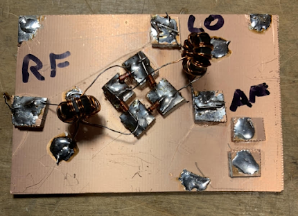
Manhattan Mixer Pads

Then it was on to the diode ring mixer.  We had planned on having the students wind their own trifilar toroids, but we realized that this might be too much -- it would add a lot of time to the build, and would introduce a lot opportunity for error.  

One of Farhan's transformers

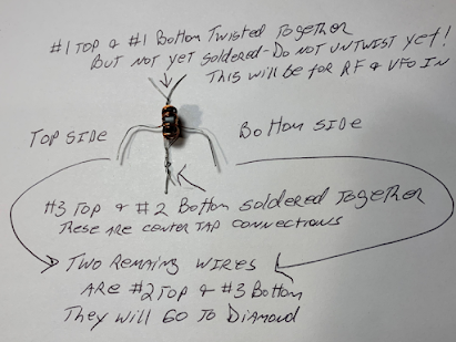
I remembered that Farhan had given me a big supply of FT-37-43 trifilar toroids that had been assembled in Hyderabad.  We decided to use these transformers.  We reasoned that this was not a big deviation from our DIY ethos -- after all, we didn't ask the student to wind their audio transformers, nor did they wind the RF choke in the VFO buffer.  But we faced a problem:   the Hyderabad transformers were all wound with the same color wire on all three turns.  This would make it hard for the students to figure out which wire went where (there were 12 such wires on each mixer board!).   I figured out how to do this:  The night before, I soldered together the center tap wires, and I twisted together the input coil wires.  We told the students to first solder the center taps in place, then solder the two free wires to the diode ring, and finally untwist the input coil wires, soldering in these connections.  This worked.  

How the transformers were prepped

Before we started, I gave the students a quick class on the essentials of mixers. And I pointed out that we were using transformers made in Hyderabad India and donated by our friend Farhan.  I told the students that whenever we include parts given to us by a ham radio friend we are adding "soul to the new machine." Indeed, Farhan's toroids added a lot of soul. 


We have been insisting that the students have each stage tested before moving on to the next.  This week we used signal generators to put RF and VFO energy into the mixers, and oscilloscopes to make sure that audio was coming out.  

One of the test set-ups for the mixers

The students are making good progress.  After today's session we did an estimate of where each of the projects stand at this point: 

We are building 15 receivers. 
Oscillation without the buffer:   11
Oscillation with the buffer: 5 
Mixer built and tested (but no diplexer yet):  5 
Mixer working, diplexer built  2

During the next month or so the students will build the bandpass filter and the audio amplifier, and put all the boards together to complete the receiver. 

Thursday, February 23, 2023

Early (1912?) Ham Station

 
Perhaps a bit overdressed by today's standards, but he's got a familiar look on his face.  Confidence and pride in his rig, and a steely determination to make contacts with it.  

If you zoom in you can see the crystal and the cat's whisker. 

More on this here: 

http://uv201.com/Photo%20Pages/ham_3.htm?fbclid=IwAR10Lbi2CAsYeiBDUjWb5KIQrh1SJVGwDyL2_1ZrkPk1VbllAUbeahwxsAI

Wednesday, February 22, 2023

The Transistor at 75, and the Raytheon CK722 (Pete's First Transistor)


https://www.eejournal.com/article/the-transistor-at-75-the-first-makers-part-1/

Part 4 is especially interesting to us because of the N6QW-CK722 connection: 

     Raytheon: Raytheon started making vacuum tubes in 1922. During World War II, the company made magnetron tubes and radar systems. Raytheon started making germanium-based semiconductor diodes in the 1940s and, just months after BTL announced the development of the transistor in late 1947, started making its own point-contact transistors using germanium salvaged from Sylvania diodes. After attending the 1952 BTL transistor symposium and licensing the alloy junction transistor patents from GE, the company quickly started making germanium transistors including one of the most famous transistors of that generation, the CK722, which was simply a rejected commercial CK718 transistor with downgraded specs for the hobby market. (Jack Ward has created an entire museum around the Raytheon CK722 PNP transistor.) Raytheon exited the semiconductor business in 1962.

Here are all of our blog posts on the CK722: 

https://soldersmoke.blogspot.com/search?q=CK722

Here is our post on Pete Juliano's CK722: 

https://soldersmoke.blogspot.com/2015/03/pete-juliano-homebrwing-with.html


Is this the Origin of the Term "Ham" Radio?

Click on the image for a better view

The timing (1895) and the context (railroad telegraphy) seem about right.  But other etymologies are out there.  Lexicographer Steve Silverman KB3SII is on the case.  What do you guys think?  Are the roots of "ham" radio in railroad telegraphy? 


Tuesday, February 21, 2023

Farhan's Direct Conversion Receiver

Thank God for the Wayback machine.  For a moment I feared that this article about Farhan's DC-40 receiver had been lost.  (Phonestack is now some Vietnamese vendor. ) But the WayBack Machine archive came through for us.  

https://web.archive.org/web/20171109081542/http://www.phonestack.com/farhan/dc40.html

Farhan's receiver has been covered on this blog before, but it is especially relevant for us now that we are immersed in our own direct conversion receiver project.  Farhan was working with his niece, who was a student.  We are working with high school students. 

I really like Farhan's blow-by-blow description of the build.  There are raw emotions here: He speaks of his hatred of LM-386s, and of how he thought of using the copper clad board as a projectile.  His niece wonders about the possibility of evil spirits in the receiver. The battle against AM breakthrough is very familiar.  (I like the RF choke idea.) You won't find candor like this in QST or QEX.  

Farhan's DC-40 project was one of the inspirations for our high school effort.  In fact, when we first went to the school, I left behind a direct conversion receiver that I had built.  Taped onto the bottom of the receiver was a quote from the DC-40 article and a picture of the Wizard of Hyderabad.  (See above, and click on the picture for a better look). 

This week we will inject some more Farhan-ismo into our receiver.  The time has come to build the mixer.  Like Farhan, we will go with the diode ring.   Winding the transformers would be very time consuming.   I remembered that on his visit, Farhan had left me a box of trifilar toroids wound by the seamstresses of Hyderabad using FT37-43 cores.  We will uses these in our build.  They will add a lot of soul to the new machine. 

Sunday, February 19, 2023

Antoine's Home Lab in Paris


Another very interestng lab brought to us by CuriousMarc.  


Saturday, February 18, 2023

Progress Report: High-School Students Melt Solder and Successfully Build Oscillators

Dean KK4DAS and I were at the high school on Thursday and Friday of this week for the construction (by the students) of the variable frequency oscillator stage of their analog, discrete, direct-conversion receivers for 40 meters.  Most of the students have already obtained their Technician Class licenses, so they are already radio amateurs.  Both the licensing classes and the receiver build are being done with the assistance of the Vienna Wireless Society. 

A week earlier Dean and I had demonstrated how to build the oscillator stage using the Manhattan technique (isolation pads super-glued to copper clad boards), but this week was the first time these students were actually building anything like this themselves. 


We deliberately did not "spoon feed" the students.  We told them that while we would be on-hand to help, THEY would have to do the building.  They would have to layout the pads on the PC board, select the parts (from a table set up by Dean), and do the gluing and soldering.  We did not hand the students bags of parts, or prepared PC boards.   This was not going to be a kit building session.  We wanted this to be real homebrewing. 

We had parts for 15 receivers.   But on the first day there were more than 60 students.  So four students per project.   On the first day we actually ran out of soldering stations.  

We cautioned the students against dawdling.  We told them to get on with it, and to "make haste slowly." We also injected an element of competition into the build by announcing that the first team to achieve oscillation would win.  (Prize still TBD).   

By the end of the Thursday session, many boards had been built but there were not yet any oscillations. We reconvened on Friday afternoon -- Dean and I set up support/troubleshooting stations. 

Right off the bat, one of the students came up with a board that he wanted to test.  After one quick correction (enamel still on the oscillator coil leads), my frequency counter showed that it was oscillating.  I fired up my DX-390 receiver and we heard the loud tone.   We had a winner! 

In the following hour or so, Dean and I did troubleshooting on about 10 more boards.   We found some of the problems that we would all expect (because we have all made these mistakes ourselves!): 

-- There were cold soldering joints.  We showed the students how to properly solder -- usually they just had to re-heat some cold-looking connections. 

-- A few of the Zener diodes and transistors were wired in backwards (been there, done that).  

-- A few of the feedback capacitors were of the wrong values.  Dean and I had brought some good caps, so the students were able to quickly swap out the parts.  This was another good lesson. 

-- There were a few wiring errors -- these were quickly corrected. 

It was exciting.  One-by-one we would hear the whoop-whoop as the DX-390 confirmed that another oscillator was OSCILLATING!  The students really liked to HEAR the oscillations that they had created.  We reminded them at the beginning that they would be taking DC from a little square 9 volt battery and turning it into RF that could (if connected to an antenna) be heard around the world, or in our case be used to receive signals from around the world.  

We got eight of the oscillators going.  We think the students will be able -- without much help from us -- to get the remaining seven oscillators going.  

They learned a lot.  They learned about the ease, flexibility, and usefulness of the Manhattan technique, and we think they could see how this represents a basic kind of PC board design.  Their soldering skills improved a lot. And they learned how to troubleshoot:  Is the layout correct?  Are any parts wired in backwards.  Is the soldering OK?   Are any of the parts bad (or of incorrect values)?  Most importantly, they learned that they CAN build circuits themselves, and actually get them working. 

The real payoff came each time oscillation was achieved. The students were really amazed and pleased.  I could tell that some of them weren't really sure their little device was actually creating the signal they were hearing.  So while we listened to the DX-390, I asked them to disconnect and reconnect the battery.  Confirmed.  Oscillation!  Smiles.   It was really great.  

Soon, after finishing up some PTO odds and ends,  we will move on to the other stages.  We'll probably do the bandpass filter or the mixer next.   Then the AF amp.  Then put it all together into a full receiver.  We think each stage will get easier and easier to build as the students learn and improve their homebrewing skills and their self-confidence. 

We've often reminded the students that what they are doing is NOT easy.  This is hard.  As new radio amateurs, they are taking on a project that most older hams never dare to take on.  They like the challenge.  They are homebrewing a real receiver. 

Friday, February 17, 2023

Ham Radio Pico Balloons Feared Shot Down by USAF


The Aviation Week article below helped to confirm some of my worst fears about the balloon thing.  For a long I've wanted to launch one of these balloons.  Recently I've been thinking about doing it from SolderSmoke Shack South (in the Dominican Republic -- they are BIG on party balloons down there!). 

https://aviationweek.com/defense-space/aircraft-propulsion/hobby-clubs-missing-balloon-feared-shot-down-usaf?fbclid=IwAR0ra3U4QPlzrNiVDNXz1UzQdDNfFUpccrQIRhVaCKkrZWHIPXQ0hwxEVKI

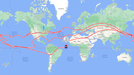
Check out Hans's site about the circumnavigators: 

http://www.qrp-labs.com/circumnavigators.html

Designer: Douglas Bowman | Dimodifikasi oleh Abdul Munir Original Posting Rounders 3 Column