fourier analiser from Gymnasiumnovum on Vimeo.
Mixer math with plywood and gears.
http://www.instructables.com/id/Plywood-Math-Machine/
http://hackaday.com/2016/04/11/fourier-machine-mimics-michelson-original-in-plywood/#more-199177
http://hackaday.com/2014/11/18/harmonic-analyzer-mechanical-fourier-computer/
Thursday, April 14, 2016
Wednesday, April 13, 2016
VE3KCL Balloon makes "several loops around Greenland"

In any case, three cheers for Dave VE3KCL and for Hans, G0UPL, the wizard who makes the QRSS/WSPR transmitter that is currently flying over Iceland.
Hi all
Some of you must have seen this already - but the rest of you may find it interesting. Dave VE3KCL launched his S-9 balloon 4 days ago (2 standard party-balloons, hydrogen-filled) with modified QRP Labs Ultimate3S QRSS/WSPR transmitter onboard.
We are using WSPR messages for tracking - one normal WSPR message and one with a special data protocol to provide altitude, speed, Maidenhead 5/6th characters, battery voltage, temperature and GPS/satellite status. The transmitter has about 16mW power output, on 30m band. It is sending CW and JT9 as well. Altitude is a little over 10,000m. So far it has traveled in several loops around Greenland and the North Atlantic. Currently it is near the Faroe islands. See live tracking at QRP Labs website http://qrp-labs.com/ultimate3/ve3kcl-balloons/ve3kcl-s9.html
G-landers, don't get too excited that it appears to be heading your way - the wind prediction shows it likely to head back West almost as far as Newfoundland, before turning back East towards Spain!
73 Hans G0UPL
Tuesday, April 12, 2016
Some Thoughts on Noise and Receiver RF amplifiers from Scotland (and listening to sun noise on 2 meters!)

Just listened to the latest SolderSmoke podcast where you asked why is it that an RF amplifier may be required on the higher bands but not on 40m and 80m for example.
At high frequencies the atmospheric and ionospheric noise levels are lower, so if noise figure of the receiver is reduced it will improve the signal to noise ratio you get from the receiver. Adding gain -after- the mixer will not improve the noise figure of the receiver as it will be limited by the noise figure of the mixer. You need an RF amplifier which will itself have a lower noise figure than a mixer (certainly a passive mixer), to lower the total noise figure of the receiver to take advantage of the lower effective antenna noise temperature at higher frequencies.
This becomes very important at VHF and above, where antenna noise levels are much lower than at HF.
So, it isn't so much the overall gain of the receiver that is important with weak signal work, but the overall receiver noise figure which is determined to the largest degree by the first stage of the receiver.
There are spreadsheets available that will easily calculate the noise figure of cascaded receiver stages knowing the individual stage gains and noise figures.
One also has to be careful with the gain distribution throughout a receiver, if you have too much gain early on in an effort to improve the noise figure overall, you may overload the subsequent stages producing IMD with multiple strong signals. So there is a compromise to be met between noise figure and strong signal performance.
Going back to VHF and above if you have an antenna fed by coax with some appreciable loss then improving the receiver RF stage noise figure is not the best way to go because you are amplifying the signal after the loss the of the coax. What you need to do in those circumstances is to use a low noise masthead RF preamplifier which will give you gain and establish the noise figure of the receiver before the loss of the coax. Again there are spreadsheets to help with these calculations.
At VHF where an antenna is pointed at the horizon, the antenna sees the noise from the ground on the noise from the sky. As we elevate an antenna for EME or satellite working, then the effect of the ground noise should reduce (there will always be some due to side lobes) and then the receiver can benefit from even lower noise figure as the effective antenna noise temperature is now mostly determined by sky noise which at UHF is much lower than ground noise.
These last two days I have been able to see and hear the sun noise on my 2m receiver as the sun set on my single 10 element yagi pointed at the horizon. Using WSJT's noise level scale I could see it measure 12dB noise level and then once the sun set it dropped back to about 3dB noise indicated, most of that being local QRN from an antenna sidelobe from my neighbour's house and his electronic devices which put out quite a bit of wideband noise on the band. (about 8dB above the lowest background level I can normally detect).
To summarise, at LF where noise is high you don't gain anything by having a low noise figure receiver, and you actually lose out if you have too much gain early on as it will degrade strong signal handling.
At HF as manmade, atmospheric and galactic noise levels are lower, you can benefit from lower receiver noise figure and the way to lower your noise figure is to use lower noise amplifiers in the early stages of the receiver. Adding gain in later stages does not reduce the noise figure overall as the noise figure is largely determined by the first stage or stages.
At VHF using even lower noise figure devices in the RF stage will improve signal to noise.
Here is a practical test you can carry out. Switch between a dummy load and your antenna. If the background noise level increases when you switch to the antenna, then your receiver is sensitive enough, lower noise figure in the receiver isn't going to help. If it doesn't increase then you have scope for improving the sensitivity of the receiver by reducing the noise figure of the receiver as you are no longer limited by antenna noise.
Incidentally it is good to have a preamplifier that can be switched in an out of circuit so that you can reduce the noise figure when conditions allow ( low noise atmospheric noise levels for example), but switch it out if noise levels are high and signals are strong so that receiver overload and IMD don't occur. You can do something similar with an input attenuator to reduce strong signals where necessary.
I don't have a link here to the graph of manmade, atmospheric and cosmic noise levels versus frequency, but once you see one it becomes obvious why low noise figure receivers are not required at LF and MF generally.
73 from David GM4JJJ
Bill,
I found the article with graph of noise v frequency at last, in Ham Radio Magazine 1975!
A good read and as valid today as then.
I don't have a link here to the graph of manmade, atmospheric and cosmic noise levels versus frequency, but once you see one it becomes obvious why low noise figure receivers are not required at LF and MF generally.
73 from David GM4JJJ
Saturday, April 9, 2016
Soldersmoke Podcast #186 Is Available -- April 1 Rap Up, Pi Talk from Pete, Collins and Raspberries, Bill's Analog RX, Visits and Hamfests, MAILBAG

SolderSmoke podcast #186 is available:
-- April 1 WireWrapRap Rap-up. Feedback from participants.
-- Bench Reports:
- Pete talks about his Raspberry Pi SDR DSP rig.
- Bill talks about on his Mate for the Mighty Midget Receiver and his R2 Frankenstein.
-- A story from Pete's youth: Cruising the "Miracle Mile" with a Heathkit "Ten-er."
-- Why do we need more RF amplification (in receivers) on 20 than on 40?
-- Have you ever tuned the BFO freq in a superhet by the "sound of the noise?"
-- A visit to Washington by Jonathan W0OX and family.
-- Bill goes to Winterfest Hamfest with Armand WA1UQO
-- Pete on the importance of balance (in life).
-- Great interviews on QSO Today: Peter Parker, Grayson Evans, and Ashhar Farhan.
-- MAILBAG:
- Paul Darlington M0XPD has a new book about life, travel, and the Dayton Hamvention.
- Michael AA1TJ QRV with a tuning fork at its 2,000th harmonic.
- Jonathan M0JGH living dangerously with homebrew QRP in Italy.
- Ben KC9DLM JoO with MMM
- Stefan DL1DF needs 3.579 MHz rock "with mojo." We have it for you OM.
The music for SolderSmoke 186 was written and performed (the bass lines) by Pete's son Tim. Thanks Tim!
Pete also suggested that we have some rap lyrics for this music, so renaissance man that he is, he composed some words. We are still looking for a performer.
Yo we solder no more – its wire wrap and cables
The cables connect to the small black box
hold on to your pants and pull up your socks
A cable goes here and a cable goes there
Turn on the switch and its Shazam all software
Friday, April 8, 2016
From Vietnam to Washington DC -- Jonathan-san KC7FYS W0XO 7J1AWL XV2OC Stops By With His AT3b

I first saw that QRP Altoid-tin ATS-3b rig around 8 years ago in pictures that Jonathan-san sent from a beach in Vietnam. He and his family were there on vacation from Japan. (Included was a memorable picture of his young son in an NVA helmet.) During this time period Jonathan also tried (unsuccessfully, I'm afraid) to teach me how to properly pronounce the name of that famous electronics market in Japan.
Jonathan and his family were in Washington yesterday and we got together for lunch. It was great to finally meet them. And to see that well-travelled ATS-3b.

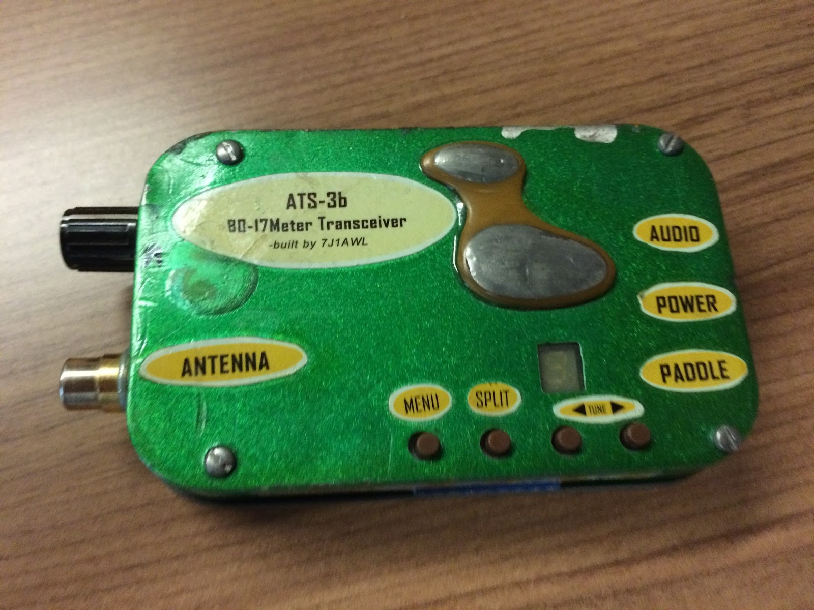
Jonathan is a big fan of the ATS-3b, and for good reason. A very neat rig.

Plug in filters for the ATS-3b.
Thursday, April 7, 2016
The meaning of "CM" in the Toyo CM-455 Filter
 |
| Photo by ZS1KE |
Today I started wondering about the passband characteristics of the device. What do the skirts look like? So I started Googling. There is not much out there, but I did come across a really interesting Epson site that describes the origins of this filter, and what the CM means. CM is for "Crystal Mechanical." Wow, this little box combines the characteristics of a crystal filter AND a Collins Mechanical filter:
An excerpt:
"While at the Electrical Communication Laboratory of NTTPC, Mr. Nakazawa had had a flash of inspiration: ‘We could develop a crystal unit with a high Q factor by using the wire mount technology I'm studying now. Then, if we can achieve the idea of a mechanical filter that mechanically joins multiple units using quartz material, we should be able to develop a compact filter that achieves both excellent filter characteristics and thermal characteristics.’ Without a pause, he quickly tackled the next development issue, which resulted in the creation of the ‘crystal mechanical filter (‘CM filter’)*5). This CM filter was manufactured by processing the quartz substrate into an ‘H’-shaped filter element and functioned by using the long thin sections on the left and right sides as resonators (Figure 1). The middle portion connecting the two sides fulfilled the role of the coupler. This was precisely the ‘mechanical filter achieved using crystal (quartz)’ that Mr. Nakazawa had envisioned.
This filter was released on the market as a 455kHz intermediate frequency (IF) filter for single-sideband (SSB) modulation in radio communications. The use of quartz material meant that not only were good filter characteristics achieved, but thermal characteristics were also excellent. As this was the first filter to offer properties of this caliber, it sold extremely well throughout the world. Furthermore, this technology received the honor of being granted the Notable Invention Award from the Science and Technology Agency."
Does anyone have the specs on these filters, and perhaps a passband graph?
Three cheers for Mr. Nakazawa!
Wednesday, April 6, 2016
The Wizard of Wimbledon writes of Emperor Hadrian's QTH, HMS Belfast, JFK and QRP

I write this to you from my shack in Wimbledon, south west London, with the crackle of the bands slowly waking up across Europe, having just devoured the final few pages of your excellent Soldersmoke book; an intriguing and entertaining tale to which many of us can relate, a highly-accessible technical primer which certainly helped me to clarify a few niggling “Yes, but why?” questions, and a compendium of handy tricks to try during future projects – thank you for sharing your story.
I was amused to read that GB2RN, on HMS Belfast in London, where I am now one of the “new boy” volunteers, was an inaugural contact for your Azorean 17m DSB rig. As it turns out, 12000 tonnes of British warship seems to play an crucial role in testing QRP radios:
Enjoying a peaceful hilltop picnic in December 2014 with my girlfriend, gazing out over the idyllic Italian countryside above Frascati, it occurred to me that what the situation really called for was a 40m QRP CW transceiver (I was possibly alone in this thought). Soon after returning home I set about researching small, reliable kits which could slip into my jacket pocket but still tune across the band.
The EGV-40 (in memory of Miguel EA3EGV, EA-QRP co-founder) seemed ideal: a “tutti frutti” architecture of well-proven designs, based around a VXO for high stability.
My construction schedule was leisurely, paced for enjoyment and attention to detail. At all times I looked to maximise reliability, crucial when operating from a hilltop, far from a workbench. To pre-harmonise the radio with an outdoor life, on sunnier occasions I often found myself soldering in the garden. For a personal touch, I made sure to instill plenty of “soul”, reminiscent of my electronics journey so far: my late grandfather's tools and solder were used throughout, alongside my own, together with reclaimed parts from old school projects and my elmer’s junk box; finally, in a shameless attempt at appeasement, my remarkably understanding girlfriend even helped to solder the final capacitor… and may be invited to recommend the paint colour!
In mid-December 2015 we once again flew out to Rome for our pre-Christmas break. Our first day was spent exploring the stunning Villa D'Este (stunning to behold, an ideal high radio QTH but far too beautiful for my wires to pollute the scenery without getting into trouble...) and Villa Adriana, near Tivoli. It was only right at the end of the afternoon, and annoyingly lower down towards the plains, when I stopped for a few minutes for an attempted sked with GB2RN.
Lesson 1: trees with lots of branches and twigs are a real pain for throwing wires through! I had guessed this already, but it truly is an exponential problem.
After conquering a geometric puzzle, I had my EFHW strung so that the point of maximum radiation was about 4m in the air – not exactly ideal for DX but theoretically reasonable for a nice high angle of radiation, like I needed. The feed point (fortunately a current null) was at roughly half this… time to get on the air!
Lesson 2: when operating outdoors – beware of the locals!
Rather than a comfortable bench I resorted to operating whilst sitting cross-legged on the grass, balancing my ex-German military miniature key on my thigh as I tapped it with my finger and attempted to steady it with my left hand.
The ambient sound of the 40m band seemed very different in I-land – that was the busiest I'd heard it outside of contests, riddled with deafening Eastern-bloc calls but not a single station from any of the British nations, which I presume must have largely been in the shade of the skip; apart from booming GB2RN beaconing to me high on the band :-)
The Villa closes at 1700 and from past experience the wardens come around at 1630 to chase stragglers out from the far corners. Annoyingly one such woman decided that my guy wire and its supporting tent peg looked highly out of place and must be interfered with. My Italian is woefully incompetent at the best of times, so I resorted to gesticulating at her wildly with my left hand as my right attempted to stay faithful to sending clear CW.
Perhaps it was for the best; had she understood that I was “Making a scheduled contact with a British warship via Morse code using home-built equipment which I had smuggled into the country by air last night", the tale might have taken an entirely different twist...
Cold hands, fading light and a dead leg from sitting in an awkward cross-legged position which is frankly impractical for anybody beyond the age of 8, but I was utterly thrilled to have enjoyed my first QSO from overseas, and particularly so since it was with my Elmer on the ship using a station which I had diligently put together myself over a number of months.
The first wisps of solder smoke have already left my iron this morning as I embark on the next stage of my QRP apprenticeship – to make the jump from a kit operator to a scratch-built home brew. All my life I have yearned to understand from first principles, and our remarkable hobby offers us a unique privilege to do so whilst sharing experience along the way.
Our objectives are decidedly more modest in scale, but I’m often reminded of President Kennedy’s famous quote: "We choose to go to the Moon in this decade and do the other things, not because they are easy, but because they are hard”.
72/3
Jonathan
M0JGH
PS Should you or any of the Soldersmoke brotherhood ever be in London and wish to operate from GB2RN, please don’t hesitate to contact me.
72/3
Jonathan
M0JGH
PS Should you or any of the Soldersmoke brotherhood ever be in London and wish to operate from GB2RN, please don’t hesitate to contact me.
Subscribe to:
Posts (Atom)