Podcasting since 2005! Listen to Latest SolderSmoke

Showing posts sorted by date for query "phase noise". Sort by relevance Show all posts

Tuesday, June 23, 2015

Video of Pete's VERY COOL Zia Build


This is cool in so many ways:

I like the RF amp along the back with the LP filter off to the side.

The stacked PC boards are very nice.

The Display -- What can I say?

Having stations from the Philippines (DU) for the receiver demo.  Nice touch.

Mesh-like side panels!  And the plexiglass top!  Wow!

PAINTING THE COPPER-CLAD FRONT PANEL BLACK!  WOW!  BLACK IS THE NEW COPPER!

Nice feet for the rig.  Feet are key.

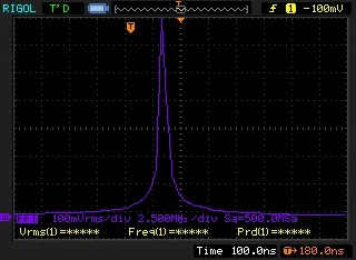
NO NOTICEABLE PHASE NOISE.  No Si5351 output bleed-over.

Love the name:  ZIA!!  (That was my only contribution.)

Saturday, June 13, 2015

SolderSmoke Podcast 177 Bicoastal Termination Insensitivity Unphased by Phase Noise

 
SolderSmoke Podcast #177 is available:
 
 
13 June 2015
 
-- PETE JULIANO INDUCTED INTO THE QRP HALL OF FAME
-- Bench Reports:  Bicoastal Bilateral Success:  A Tale of Two Tias
    Only 3 TIA rigs in the world?  It depends...
    Relay improvements in the BITX Builds
    Straightening out amp problems
    The many uses of copper foil
    No phase noise or bleed-over troubles
    Plug-in filters
    Adjusting TIA amp gain on RX and TX (too much is not good!)
    Getting the BITX to work with the CCI amp
    Allison wisely prescribes 3 db pads 
    Curing hum by moving the power supply (duh!)
-- Farhan's New Minima -- Crying out for an Si5351?
-- Mike KL7R's Web Site is Back (thanks to W8NSA)
-- SolderLex: Rigs or Radios?  We go with Rigs
-- A ham rite of passage:  Build a Dipole!
-- What does your shack look like at the end of a project?
-- MAILBAG 
    The CORRECT pronunciation of Belthorn
    Multiplication and Division by 4
    W8NSA, Vietnam, a Transoceanic and a 9V Battery 


Our book: "SolderSmoke -- Global Adventures in Wireless Electronics" http://soldersmoke.com/book.htm Our coffee mugs, T-Shirts, bumper stickers: http://www.cafepress.com/SolderSmoke Our Book Store: http://astore.amazon.com/contracross-20

Friday, February 20, 2015

Italy, Spain, Gibraltar, a Flight to Prague, and How the Mighty Mite Really Works


Gab IZ1KSW is a true Knack-afflicted member of the International Brotherhood of Electronic Wizards:  He is an Italian homebrewer who lives in Spain and works in Gibraltar.  At the end of this e-mail exchange he has a great story about reading "SolderSmoke -- The Book"  on a flight to Prague with his Greek girlfriend. It reminded me a bit of the problems I've had with fellow passengers while reading "Hot Iron" on the Washington DC train system. 

A blog post about Gab's version of the Mighty Mite is here: http://soldersmoke.blogspot.com/2015/02/iz1ksws-italian-mighty-mite-video.html
His desire to REALLY understand the circuit is, I think, admirable.  I know that my quick explanation of how the Mighty Mite circuit works isn't complete, and I'm sure that others will jump in with more details.   

........................

Hi guys,
I write to you because I'm a bit lost.
Ok, the MMM is oscillating, brilliant! 
Now I'd like to understand why it's working and how it's working.
I've been sitting on the workbench with the schematics in front of me and I found some resources on the internet, I've understood the concept of feedback loop but what really make me scratching my head is that I cannot match the MMM schematic with anyone of the typical oscillator design I found (Pierce, Colpitts, Hartley).
I've read online that it can be considered as a Pierce oscillator but from what I've found online I cannot find the purpose of the tapped coil. Maybe you can point me in the right direction before my GF starts complaining about the pile of schematics I'm accumulating in the living room!
Also, if you have any books to recommend, I'll be happy to go "back to the books"

Thank you and 73
Gab - IZ1KSW

.................


OK Gab.   I've been meaning to do this.  This little circuit needs some explanation.   I'll take a shot: 

Start by thinking of this circuit as an amplifier.  The 27 ohm resistor from the emitter to ground (negative terminal) puts a limit on how much current will flow.

The 10K resistor from the base to the positive terminal puts a positive voltage on the base and biases it so that current will flow through the transistor.

Now the fun begins!   It is an amplifier, but it has no input signal!  The input signal is the output signal -- it is like a dog chasing his tail!

The crystal is very important.  It is the main frequency determining element, and it is the conduit for the feedback that gets this thing oscillating.  It is a piece of quartz.  If you put a voltage across it, it will begin vibrating (physically) at a specific frequency.  As it physically vibrates, it also creates electrical vibrations.

So, when you turn this thing on, noise in the circuit will put a bit of charge on the crystal.  It will begin to ring, much like a musical tuning fork.  The electrical vibrations from the crystal will go to the base.  They will be amplified by the transistor and will emerge (stronger) from the collector.   From the collector, they go to the 3.579 MHz  tuned circuit formed by the big coil and the variable capacitor.

The coil wound on the film box serves several purposes. The portion of the coil between the positive terminal and the collector carries the 12V DC to the collector of the transistor.  It also carries the amplified 3.579 MHz signal coming from the collector.  This signal goes through the lower portion of the coil and causes the coil and the capacitor to resonate.  The signal at the top of the tuned circuit peaks when the tuned circuit is tuned to.... 3.579 MHz.

The capacitor/coil tuned circuit (with the tapped coil) are set up so that the right amount of energy is fed back from the output to the input, and that this energy is fed back in the proper phase relationship to the signal at the input.  Think of a child's swing at a park:  To keep the swing oscillating, you have to push at the right moment (frequency and phase) and with the right amount of energy. 

The little capacitor across the battery is to prevent "key clicks."   The output coil on the main coil takes some of the energy and sends it to the antenna while converting the impedance of the antenna to a suitable "load" for the transistor.

Whew,  how did I do?  Lots of electronics and physics in those 7 parts!

73  Bill    

................ 

Hi Guys,
 Bills explanation is absolutely perfect –but there is some additional Math in the woodworks known as the Barkhausen criteria where kB = 1
 73’s
Pete N6QW

...............

Well, what can I say Bill? Grazie mille!!
I keep thinking that you would have been a great teacher, you have the rare ability to explain complicated concepts using simple words. 
Yesterday I finished reading your book SolderSmoke GAWE (yes, you deserve an acronym too) and there have been several "eureka" moments while I was reading it. It gave me a lot of motivation to go in depth and understand what's going on in a circuit down to the physics of the components. I got the Kindle version but I'll order the paper version too, I love the hand make schematic and they're not very readable in the electronic version, plus I believe that a book about radio home brewing must be in the old fashioned paper version don't you think?
There's a funny story about the book. Few days ago I was on a flight to Prague with my YL, I was reading the book and zooming on the schematics to see them better, I was really into it and I didn't notice that the guy sitting on the seat next to me started to look at the kindle nervously, he probably though I was an bomb home brewer HI! So I decided to pass the Kindle to Angeliki so that she could read her books. She's Greek and she started reading a Greek book, written with the Greek alphabet which looks quite weird if you don't know it. At that point probably the guy thought to be sitting in the middle of some exotic terrorist... it was funny.

Wow... as most of the Italians do, I talked too much! Thanks again both for the big effort you make spreading the tribal knowledge with the podcast, the ARCI LBS articles and the books. 
Siete fantastici!

73 
IZ1KSW - Gab


Our book: "SolderSmoke -- Global Adventures in Wireless Electronics" http://soldersmoke.com/book.htm Our coffee mugs, T-Shirts, bumper stickers: http://www.cafepress.com/SolderSmoke Our Book Store: http://astore.amazon.com/contracross-20

Monday, October 20, 2014

Has AA1TJ Joined the FMLA?


I have learned that esteemed homebrewer Michael Rainey, AA1TJ, recently whipped up a 56 MHz, quarter-wave, helical coaxial resonator (BTW: the spoon is also homebrew).  Hmm, 56 Mhz.  Or perhaps we should say MegaCYCLES?  Michael claims this device is for a low phase- noise VFO, but I find the frequency selection highly suspicious.   The last time I heard of that frequency it had to do with an underground group set up by the late (or not so late) Frank Jones.  
Here is all the info on Frank's Five Meter Liberation Army.  

http://www.sunflower.com/~brainbol/frank/

A man of the '30s awakens one night in the '90s (episode 13) with a new mission: recapture 56-60 mc. He forms a Five Meter Liberation Army from his mobile home in a Barrio trailer park run by Tom Joad of Steinback's Grapes of Wrath (episode 9), and soon draws a decidedly uncolorful bodyguard (episode 7). A six foot tall half Mexican stockbroker named for Ayn Rand makes him rich and a demonic white ferret and a half-siamese cat become his familiars. (episodes 10 and 9). The leader of all this, called only "Frank," settles down in the narrator's basement to be joined by Maj. Armstrong (episode 8), Hiram Maxim (episode 23) and one-time pals Carl and Jerry from the 1950s Popular Electronics (episode 25). His huge 1940s sedan, with contemporary plates, is immune from police (episode 13 et seq) and his breadboarded electronic creations recall those distant days when a ham built his own rig and could "fix a radio." Of course all this is crazy. No one builds anything anymore and the other things Frank stands for, like self- reliance, tolerance and a generally Boy Scout viewpoint are simply out of step. Frank knows that too (episode 20), but he does not care. If you're standing in the middle of the road and see a big brown Frazer coming at you, you better jump - one way or the other.

VIVA EL FMLA!  VIVA!


Our book: "SolderSmoke -- Global Adventures in Wireless Electronics" http://soldersmoke.com/book.htm Our coffee mugs, T-Shirts, bumper stickers: http://www.cafepress.com/SolderSmoke Our Book Store: http://astore.amazon.com/contracross-20

Saturday, January 5, 2013

Signal Generator Ideas


Hi, Bill

Howzabout a generator that goes from 1 Hz to 40 MHz with 1 Hz resolution, adjustable cursor so you can step any of the 8 digits, presettable offsets for if frequency, repeater offset, or r.i.t., directly synthesized output so almost no phase noise and 12 bit waveform accuracy? How about a price tag of less than $20 for all the major parts? Start by Googling dd_synth.asm for control software, and rather than buying the PCB recommended in the notes at the head of the program, search for AD9850 on Ebay for the synthesizer board and LCD 16x2 for the display. A 16f628a PIC is a couple bucks. Both the display pinout and the synthesizer pinout match standard perfboard. For a little more than $10 more get the AD9851 board and the upper frequency limit is 60 MHz.

A better way to transistorize the old tube-type generator is to use a dual-gate RF mosfet for the oscillator. You can trim the gain for waveform purity by adjusting the bias on gate 2. Once you find the optimum bias on each band, diode-switch the bias level with the bandswitch. Since gate 2 has an extremely high impedance you can use resistors in excess of a megohm, so it won't affect the Q of the tank coil.

Jim Daldry
Raleigh NC


Our book: "SolderSmoke -- Global Adventures in Wireless Electronics" http://soldersmoke.com/book.htm Our coffee mugs, T-Shirts, bumper stickers: http://www.cafepress.com/SolderSmoke Our Book Store: http://astore.amazon.com/contracross-20

Saturday, May 12, 2012

EDN Article on Performance of Modern Ham Transceivers

Mike, KC7IT, alerted us to a very interesting EDN article about the performance of modern ham transceivers:
http://www.edn.com/article/521690-High_performance_HF_transceiver_design_A_ham_s_perspective.php?cid=Newsletter+-+EDN+Fun+Friday


On the phase noise, how do old fashioned LC or crystal oscillators compare to modern PLL or DDS circuits?


And congrats to Elecraft for the high ratings on their K3.


Our book: "SolderSmoke -- Global Adventures in Wireless Electronics" http://soldersmoke.com/book.htm Our coffee mugs, T-Shirts, bumper stickers: http://www.cafepress.com/SolderSmoke Our Book Store: http://astore.amazon.com/contracross-20

Tuesday, September 1, 2009

A Good Old VFO (by Rick, KK7B)

Here is another really great message from Rick, KK7B, sent to the emrfd yahoo group: [emrfd] A Good Old VFO Saturday, August 22, 2009 10:29 PM From: Rick To: emrfd@yahoogroups.com For several critical receiver applications in my lab I've used old Collins PTOs converted to solid state (I just replace the triode in the classic Hartley circuit with a J310 and run the circuit from a 9 volt regulator). I have half a dozen of them in dedicated propagation study receivers, and one SSB exciter I occasionally use on UHF. The other day I was changing something else in one of my receivers and connected the solid-state PTO to the frequency counter on my bench. The PTO was set to 3.100000 MHz. From a cold start (it hadn't been turned on for years) it drifted three Hz over the first ten minutes, and then a total of 10 Hz over the next few hours. When I calibrated one of my 144 MHz propagation study receivers 25 years ago, total frequency drift was <18Hz/hour. I expect most of that was aging of the overtone crystal oscillator in the premix circuit. Old Collins PTOs are common (someone at Dayton this year had a box of unknown ones in decent shape for $10 each, and there are R390 PTOs in the current Fair Radio flyer). I've never had one fail, tuning resolution is infinite, phase noise is low, digital noise is zero, and once I build one into a receiver, that part of the project is done--no improvements, software upgrades, needed. My research receivers are connected to a baseband Fourier analyzer (yes...even 25 years ago). The finest resolution I've used for serious experiments is 10 milliHertz, but more often I use 1 Hz resolution, with 1024 channels in the output spectrum. I often average spectra for more than a minute, so frequency drift needs to be less than 1 Hz per minute. The solid-state Collins PTO is much more stable than needed even for those critical experiments. This is not a fluke. Every Collins PTO I've converted to solid state using a U310 or J310 has had similar performance. Sometimes it is useful to remember that the major benefit of digital frequency synthesis is that it is quick, cheap, and frequency agile. No commercial manufacturer could afford to build a transceiver with a Collins Mil-Spec PTO in it these days. But for an amateur with mechanical skills or access to surplus hardware who needs just one good oscillator, the venerable Hartley with a temperature compensated tuned circuit and a JFET can provide outstanding performance. In music, art, architecture, automobiles, motorcycles. .. there are recognized "golden eras" where some combination of factors resulted in technical hardware that is widely recognized as being superior to what is being produced today. Often the difference is directly related to the amount of skilled labor needed during production. As technical hobbyists, we automatically assume that new is better, but as experimenters, we should be open to the idea that sometimes the technology, ideas, and block diagrams of an earlier era are superior to the cost-driven disposable technology coming off fully automatic assembly lines in some out-of-the-way place with inexpensive labor and attractive business tax codes. The idea that old technology designed decades ago by retired guys might be better than new technology is a radical concept in electronics. But NASA is using a brand new, hand built, Traveling Wave vacuum tube in the current Moon exploration mission. After 100 years of radio experiments- -it is fun to look back and find old technology that might actually work better than some of the new things we've been inventing recently. Best Regards, Rick KK7B
Designer: Douglas Bowman | Dimodifikasi oleh Abdul Munir Original Posting Rounders 3 Column